rfm301en21h09
1/3
Thank you for choosing a NIVELCO instrument!
1. APPLICATION
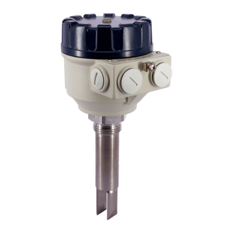
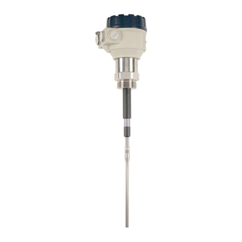
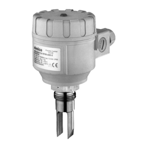
NIVOSWITCH RF–2–, RF–3–vibrating forks are designed for detection of level of powders
and granules. When they are used as high or low fail safe switches overfilling and emptying of silos and other
containers can be prevented. The RF fork series (base model, insertion length = 125 mm [4.9"]) with cast forks
are recommended for small granules, while the RR fork series (base model, insertion length = 137 mm [5.4"])
with welded forks are recommended for larger granules. Dust-Ex versions of the R–300 forks with aluminum
housing are also available.
2. TECHNICAL DATA
2.1 GENERAL DATA
Type R–3–R–2–
Material of wetted parts 1.4571 stainless steel
Process connection As per order code
Housing material Powder-coated aluminum Plastic, PBT, fiberglass-reinforced
Temperature
ranges
Medium –40…+130 °C (–40…+266 °F); PP flange: –20…+90 °C (–4…+194 °F)
Ambient –40…+70 °C (–40…+158 °F)
Medium pressure Up to 40 bar (4 MPa, 580 psi) see: 2.5 diagram
Insertion length 125…3000 mm (5″…10 feet), as per order code
Medium density 0.01 kg/d m3(>0.7 S.G.)
Response
time
Getting immersed 0.5 sec
Getting free 1 sec at high-density setting (0.5 kg/dm3)
3 sec at low-density setting (< 0.5 kg/dm3)
Operating mode indicator Two-tone LED
Operating mode selection Switch for selecting HIGH or LOW fail-safe mode
Density adjustment Switch for selecting HIGH or LOW Density
Output (1) 1 or 2 SPDT relays
Relay 1: 250 V AC, 8 A, AC1 / Relay 2: 250 V AC, 6 A, AC1
Electrical connection (1)
2× M20x1.5 cable glands for Ø6…12 mm (Ø0.25″…0.5″) cable;
2× internally threaded ½″NPT connection for protective pipes.
Terminal blocks for max. 1.5 mm² (AWG16) wire cross section
Power supply (1) 20…255 V AC/DC
Power consumption DC: < 3 W
Electrical protection Class I
lngress protection IP67
Weight 1.3 kg + 1.2 kg/m (~2.86 lb + 1 lb/ft) 0.95 kg + 1.2 kg/m (~2 lb + 1 lb/ft)
(1) For Ex type, see chapter 2.2 Explosion protection, Ex markings, Ex limit data.
2.2 EXPLOSION PROTECTION,EX MARKINGS,EX LIMIT DATA
2.2.1 ATEX certificate, No. BKI16ATEX0011/1
R
3
B Ex
Ex marking II 1/2 D Ex ta/tb IIIC T140 °C Da/Db
Power supply (universal) 20…250 V AC (50/60Hz) or 20…50V DC
Electrical connection
2× M20x1.5 Ex ta IIIC cable glands for Ø7…12 mm (Ø0.28″…0.5″) cable;
2× terminal blocks for max. 1.5 mm² (AWG16) wire cross section
2× internally threaded ½″NPT connection for protective pipes
Temperature ranges Medium
40…+130 °C (
40…+266 °F)
mbient
40…+70 °C (
40…+158 °F)
Output 1× SPDT relay 250 V
C, 8 A, AC1
Reference document number rfm3010m060bh_09
2.3 ACCESSORIES
User’s manual – 2× M20x1.5 plastic cable gland
Warranty Card – 1× 2 mm (0.08″) thick KLINGER OILIT seal (only for 1" BSP-threaded process connection)
EU-Declaration of Conformity – 2× plug-in type, 3-pole terminal block (3× for models with 2 relays)
2.4 RESPONSE TIME –MEDIUM VISCOSITY DIAGRAM
2.5 PRESSURE –TEMPERATURE DIAGRAMS
Medium pressure (pT) – Medium temperature (TM)
Medium pressure (pT) – Medium temperature (TM) PP flange version
