manuals.online logo
Brands
  1. Home
  2. •
  3. Brands
  4. •
  5. NIVELCO
  6. •
  7. Switch
  8. •
  9. NIVELCO NIVOSWITCH R-400 User manual

NIVELCO NIVOSWITCH R-400 User manual

rcm400en2111h 1/4
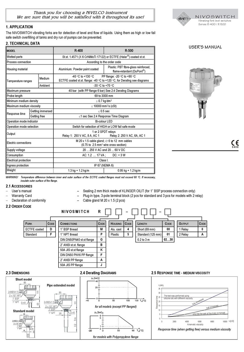
Thank you for choosing a NIVELCO instrument.
We are convinced that you will be satisfied with our product!
1. APPLICATION
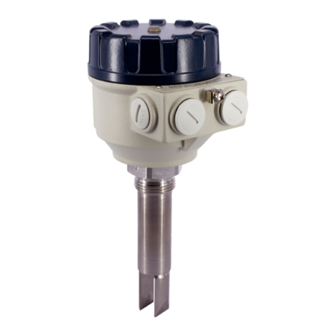
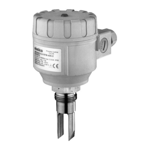
A NIVOSWITCH R–400 type vibration forks are applicable for level switching or flow switching tasks of
normal and explosive liquids. Overfill or dry run protection, as well as pump control, is also possible with the
NIVOSWITCH vibration forks in low/high fail-safe operation mode.
2. TECHNICAL DATA
2.1 GENERAL DATA 2.2 TWO-WIRE DC,
NORMAL AND EX APPROVED VERSION
R–400 / R–400 Ex TYPE R–4–6
R–4–8Ex
R–4–K
R–4–L Ex
R–4–7
R–4–9Ex
Medium pressure
40 bar (580 psi),
PP flange: 6 bar (87 psi)
see “Temperature diagrams”
Electrical connection Connector
3 m (10 ft) cable
(2 x 0.5 mm2
[AWG20])
Insertion length 69…3000 mm (0.225…10 ft) Ingress Protection IP65 IP67 IP68
Material of wetted
parts
DIN 1.4571,
ECTFE / PFA coating Output
DC current change:
When free: 9 ±1 mA;
When immersed: 14 ±1 mA
Medium
temperature
−40…+130 °C (−40…+266 °F)
see table in 5.1 and diagrams
Consumption < 0.5 W
Power supply (U)
15…29 V DC
Provided by the PKK–312–8Ex
remote switching unit for the Ex-version
Ambient
temperature
−40…+70 °C (−40…+158 °F)
see table in 5.1 and diagrams
R–4–L Ex;
R–4–M and –4–K
−25…+70 °C (−13…+158 °F)
Setting operation
mode
By switch on the remote switching unit
(Low fail-safe – “L”, High fail-safe – “H”)
Medium-density 0.7 kg/dm3Electrical protection Class III.
Medium viscosity 10000 mm2/s (cSt)
Response
time
When
immersed 0.5 sec
Ex marking
(RC–4–Ex,
RG–4–Ex)
II 1G Ex ia IIC T6…T4 Ga
When free When free: 1 s
see response time diagram Ex marking
(RB–4–Ex) II 1G Ex ia IIB T6…T4 Ga
Output mode
indication Bi-color (LED) Intrinsically safe data
Ui= 29 V; Ii= 100 mA; Pi= 1.4 W;
Ci= 7 nF; Li= 0 mH
For temperature classes see 5.1.
Operation test Output can be changed
by test magnet
Reference document
number rcm4004m0600h_10
2.3 WIRE AC AND 3-WIRE DC VERSIONS
TYPE 2-WIRE AC 3-WIRE DC
R–4–1 R–4–2 R–4–3 R–4–M R–4–4
Electrical connection (wire cross section) Connector
3 m (10 feet) integral cable,
4 x 0.75 mm2(AWG18)
(max cable length 30 m [100 feet])
Connector
3 m (10 feet) integral cable,
5 x 0.5 mm2(AWG20)
(max. cable length 30 m [100 feet])
Mechanical protection IP65 IP68 IP65 IP67 IP68
High/low mode setting
(Low fail-safe – “L”, High fail-safe – “H”) Connection within connector Wire selectable Switch selectable Connection within
connector Wire selectable
Output 2-wire AC, for serial connection Field selectable,
PNP/NPN transistor switch
Field selectable, galvanically
isolated PNP/NPN transistor switch
Output protection — Reverse polarity, overcurrent and short-circuit protection
Supply voltage 20…255 V AC, 50/60 Hz 12…55 V DC
Consumption Depending on load < 0.6 W
Voltage drop (in switched-on state) < 10.5 V < 4.5 V
Electrical protection Class I Class III
Current load
max. continuous 350 mA AC 13 Imax = 350 mA DC / Umax = 55 V DC
min. continuous 10 mA / 255 V, 25 mA / 24 V –
max. impulse 1.5 A / 40 ms –
Residual current (in switched off state) < 6 mA < 100

A
2.4 ACCESSORIES
- User’s manual - EU- declaration of conformity - 1× Sealing ring (2 mm [0.079"] thick Klinger Oilit)
- Warranty Card - 1× RPS
–
101 type test magnetic-screwdriver (optional) - Sliding sleeve for adjustable types: RPH
–
112 (optional)
2.5 ORDER CODES NIVOSWITCH R – 4 – *
TYPE CODE PROCESS CONNECTION CODE PROBE LENGTH CODE OUTPUT
/
CERTIFICATES CODE
Tube + plastic
(ECTFE / PFA) coated fork B 1" BSP M Short (69 mm [2.7"]) 00 2-wire AC + connector 1
1½" BSP H Standard (125 mm [4.9"]) 01 2-wire AC + cable 2
Tube + fork: 1.4571 C 1" NPT P 0.2…3 m (0.66…10 feet) 02…30 3-wire DC + connector 3
Tube + highly polished fork G 1½" NPT N 3-wire DC + cable 4
Tube + fork: 1.457, without reed sensor(1) E DN50 PN16 PP DIN F 2-wire DC + connector 6
(1)Ex version not available DN50 PN40 1.4571 DIN G 2-wire DC + cable 7
ANSI 2" RF150 PP A 2-wire DC + connector + Ex 8
ANSI 2" RF600 1.4571 B 2-wire DC + cable + Ex 9
JIS 10K 50A PP J 2-wire DC + M12 connector K
JIS 40K 50A 1.4571 K 2-wire DC + M12 connector + Ex L
TriClamp 1½" T 3-wire DC + M12 connector M
TriClamp 2" R
DN40 Pipe coupling D * Ex version with Ex mark
DN50 Pipe coupling E Note: Flanged versions have 1" process connection
2/4 rcm400en2111h
2.6 TEMPERATURE DIAGRAMS
Pressure [pT] as a function of temperature [TM] for all versions
(except PP flanged version)
55
45
35
I
L
100 mA
I 1mA
L
I350mA
L
95
105
130
115
70
T[°C]
M
T[°C]
A
-40
-40
Temperature limits of DC versions, [IL] load current
0
050
p [bar]
T
6
5
1
-20 90 T[°C]
M
Pressure [pT
]
as a function of temperature [TM
]
for PP flanged version
55
130
115
70
T[°C]
M
T[°C]
A
-40
-40
Temperature limits of AC versions, [TA] ambient temperature
[TM] medium temperature
2.7 RESPONSE TIME DIAGRAM (WHEN GETTING FREE)
2.8 DIMENSIONS
R–400–“short” R–4–
Version with sliding sleeve Version with flange
TriClamp (ISO 2852) Pipe coupling
2.9 MATERIALS
3. INSTALLATION
Prevent the device from any mechanical damage.
For positioning the fork-tines, use the marking on the hexagonal neck.
If directional positioning of the fork-tines is
needed (side mounting), use the Teflon
(PTFE) tape to seal the thread and
position the fork-tines to the desired
direction
In this case vertical positioning of the fork-
tines is suggested.
rcm400en2111h

3/4
Low viscosity liquids
On applications, where the fork-
tines are easily freed from the
process medium, any of the
mountings shown to the right is
possible.
High viscosity liquids
On applications, where the fork-
tines are not freed easily from
the process medium, horizontal
mounting is recommended.
Installation options
Threaded version Flanged version, critical distances
x
> 5 mm
(
0.
2
"
)
For pipe mounting, fork-tines must be parallel to the direction of flow
Switching point and differential for water at 25 °C (77 °F)
The switching point, as well as the switching differential, depends on the liquid
density and mounting position.
4. WIRING
4.1. 3-WIRE AC VERSIONS R–4–1 (connector)
R–4–2 (cable)
Do not power up the device without a load connected in series
with the unit and without grounding it!
4.1.1. Version with connector R–4–1
“L” Low-level limit switch “H” High-level limit switch
Terminal block cover can be rotated in 90° steps to ensure appropriate cable
positioning.
4.1.2. Version with cable R–4–2
This version is with 4-wire cable equipped. Only one of the black and brown wires
is used, dependent on the operating mode (High or Low).
Provide also a terminal block connection for the unused wire.
“L” Low-level limit switch “H” High-level limit switch
4.2. 3-WIRE DC VERSIONS
In case of overload caused by a short circuit, the transistor will switch on and off,
and LED will start to blink.
4.2.1. Version with connector R–4–M, R–4–3
4.2.1.1. Wiring of 3-wire DC version with connector in case of relay application
PNP wiring NPN wiring
Terminal block cover can be rotated in 90° steps to ensure appropriate cable
positioning.
PNP output
“L” Low-level limit switch “H” High-level limit switch
NPN output
“L” Low-level limit switch “H” High-level limit switch
4.2.1.2. Wiring of 3-wire DC version with connector in case of PLC application
PNP wiring
4.2.2. Version with cable R–4–4
4.2.2.1. Wiring in case of relay applications
PNP output
“L” Low-level limit switch “H” High-level limit switch
4/4 rcm400en2111h
NPN wiring
“L” Low-level limit switch “H” High-level limit switch
4.2.2.2. Wiring in case of PLC applications
PNP wiring
“L” Low-level limit switch “H” High-level limit switch
4.3. 2-WIRE DC VERSIONS,NORMAL OR EX
4.3.1. Version with connector
R–4–6
R–4–8Ex
R–4–K
R–4–LEx
4.3.2. Version with cable R – 4 – 7
R – 4 – 9Ex
5. PUTTING INTO OPERATION, ADJUSTMENT
Check connecting of the wires and position of the mode of operation switch
(if there is). After connection and power up the tuning fork is operational.
Operation diagram of the NIVOSWITCH:
Power
supply Fork Mode Display
(LED) Output
ON
Immersed
High Red OFF
Low Green
ON
Free
High Green
Low Red
OFF
NONE
Free
or
immersed
H
or
L
Not Lit
Operation diagram of the 2-wire DC version
Fork Display (LED) Output
Immersed
Red 14 1 mA
Free
Green 9 1 mA
OPERATION TEST
Correct operation of the switching circuit of
an installed device can be tested with the
optional test magnet (RPS–101).
Moving the test magnet in front of the
marking on the cover of the housing the
device must perform a switching (LED
changes color).
5.1. APPLYING EX APPROVED MODELS
Applying Ex-approved models take into consideration the table of allowed
temperatures listed below.
Temperature
classification T6 T5 T4
Tambient 70 °C (158 °F) 60 °C (140 °F) 60 °C (140 °F) 60 °C (140 °F)
Tmedium 70 °C (158 °F) 75 °C (167 °F) 95 °C (203 °F) 130 °C (266 °F)
Table of possible temperatures
Installation proposal
5.2 CONDITIONS OF SAFE OPERATION
ATEX II 1G Ex ia IIC T6…T4 Ga and II 1G Ex ia IIB T6...T4 Ga approved vibrating
forks should be powered by intrinsically safe [Ex ia IIC or IIB] certified and
approved devices.
The cleaning of these units are allowed only with a wet rag.
Junction box shall be applied for R–4–9Ex versions with cable
connection. Junction box shall meet the appropriate protection requirements.
The instrument has built-in overvoltage protection, so:
Outer grounding of the electric housing shall be connected to the steel silo
wall with a minimal 4 mm2(AWG12) cross-sectioned, shielded copper cable
─outside the Zone 0 ─within the distance of 1 m (3.3 ft) from the
boundary of the Zone 0.
According to point 6.3.12 of EN 60079-11 standard dielectric strength test is
not allowed to perform with the instrument.
To avoid the danger of electrostatic charge accumulation, in case of the coated
version RB–4–type the following safety rule shall be observed:
Measured medium shall be an electrostatic conductor, electrical resistivity of
the medium shall be 104.
Speed of the filling and emptying process shall be chosen properly according
to the measured medium.
6. MAINTENANCE, REPAIR
In some instances, the sensor probe may
need occasional cleaning to remove surface
deposits. This must be carried out gently,
without harming the vibrating section of the
vibrating fork.
Before returning the device for repairs, it must be cleaned carefully, the parts in
contact with the medium that might contain harmful substances must be
decontaminated. Our official form (Returned Equipment Handling Form) must be
enclosed. Download it from our website www.nivelco.com. The device must be
sent with a declaration of decontamination. Please provide a statement in the
declaration that the decontamination process is completed, the device is clean
and free from harmful materials, and there are no hazardous substances on it.
7. STORAGE CONDITIONS
Ambient temperature: −25…+60 °C (−13…+76 °F)
Relative humidity: max. 98%
rcm400en2111h
May 2021
NIVELCO reserves the right to change technical specifications without notice.

This manual suits for next models

1

Other NIVELCO Switch manuals

NIVELCO R-400 User manual

NIVELCO

NIVELCO R-400 User manual

NIVELCO Nivocap CK User manual

NIVELCO

NIVELCO Nivocap CK User manual

NIVELCO NIVOPOINT User manual

NIVELCO

NIVELCO NIVOPOINT User manual

NIVELCO NIVOSWITCH R-400 Series User manual

NIVELCO

NIVELCO NIVOSWITCH R-400 Series User manual

NIVELCO NIVOPOINT MR Series User manual

NIVELCO

NIVELCO NIVOPOINT MR Series User manual

NIVELCO NIVOSWITCH R-2 Series User manual

NIVELCO

NIVELCO NIVOSWITCH R-2 Series User manual

NIVELCO NIVOFLIP MAK-100 Series User manual

NIVELCO

NIVELCO NIVOFLIP MAK-100 Series User manual

NIVELCO NIVOCONT K User manual

NIVELCO

NIVELCO NIVOCONT K User manual

NIVELCO MR Series User manual

NIVELCO

NIVELCO MR Series User manual

NIVELCO NIVOFLIP MAK-200 User manual

NIVELCO

NIVELCO NIVOFLIP MAK-200 User manual

NIVELCO NIVOSWITCH R-400 Series User manual

NIVELCO

NIVELCO NIVOSWITCH R-400 Series User manual

NIVELCO NIVOFLOAT NW-100 Series User manual

NIVELCO

NIVELCO NIVOFLOAT NW-100 Series User manual

NIVELCO NIPRESS DK-500 Assembly instructions

NIVELCO

NIVELCO NIPRESS DK-500 Assembly instructions

NIVELCO NIVOSWITCH R-400 Series User manual

NIVELCO

NIVELCO NIVOSWITCH R-400 Series User manual

NIVELCO NIVOMAG MK-21 Series User manual

NIVELCO

NIVELCO NIVOMAG MK-21 Series User manual

NIVELCO NIVOCONT R Series User manual

NIVELCO

NIVELCO NIVOCONT R Series User manual

NIVELCO NIPRESS DK-300 Assembly instructions

NIVELCO

NIVELCO NIPRESS DK-300 Assembly instructions

Popular Switch manuals by other brands

Eaton P5-125/Z Instruction leaflet

Eaton

Eaton P5-125/Z Instruction leaflet

Raymarine SeaTalk HS installation guide

Raymarine

Raymarine SeaTalk HS installation guide

WINK PWHUB-WH18 Getting started

WINK

WINK PWHUB-WH18 Getting started

TP-Link TL-SG1005P installation guide

TP-Link

TP-Link TL-SG1005P installation guide

H3C S9505 SRP installation manual

H3C

H3C S9505 SRP installation manual

Blackbird 4K HDMI 2.0 user manual

Blackbird

Blackbird 4K HDMI 2.0 user manual

HP ProCurve 5400zl Series Read me first

HP

HP ProCurve 5400zl Series Read me first

D-Link DGS-3120-24PC-SI Hardware installation guide

D-Link

D-Link DGS-3120-24PC-SI Hardware installation guide

SY Electronics OMEGA 3 user manual

SY Electronics

SY Electronics OMEGA 3 user manual

CyberData External Hub Specification sheet

CyberData

CyberData External Hub Specification sheet

AGILTRON NanoSpeed F Series Operation manual

AGILTRON

AGILTRON NanoSpeed F Series Operation manual

TP-Link Omada DS105GP installation guide

TP-Link

TP-Link Omada DS105GP installation guide

UTAH SCIENTIFIC Utah-400 iP Setup & operation

UTAH SCIENTIFIC

UTAH SCIENTIFIC Utah-400 iP Setup & operation

Digital Electronics Corporation ST Series installation guide

Digital Electronics Corporation

Digital Electronics Corporation ST Series installation guide

PASCO ME-9259A instruction sheet

PASCO

PASCO ME-9259A instruction sheet

KROHNE OPTISWITCH 5300 C Handbook

KROHNE

KROHNE OPTISWITCH 5300 C Handbook

Westermo Lynx DSS L206-S2 user guide

Westermo

Westermo Lynx DSS L206-S2 user guide

Eterna TLS68EX installation instructions

Eterna

Eterna TLS68EX installation instructions

manuals.online logo
manuals.online logoBrands
  • About & Mission
  • Contact us
  • Privacy Policy
  • Terms and Conditions

Copyright 2025 Manuals.Online. All Rights Reserved.