Thank you for choosing a NIVELCO instrument
We are sure that you will be satisfied with it throughout its use!
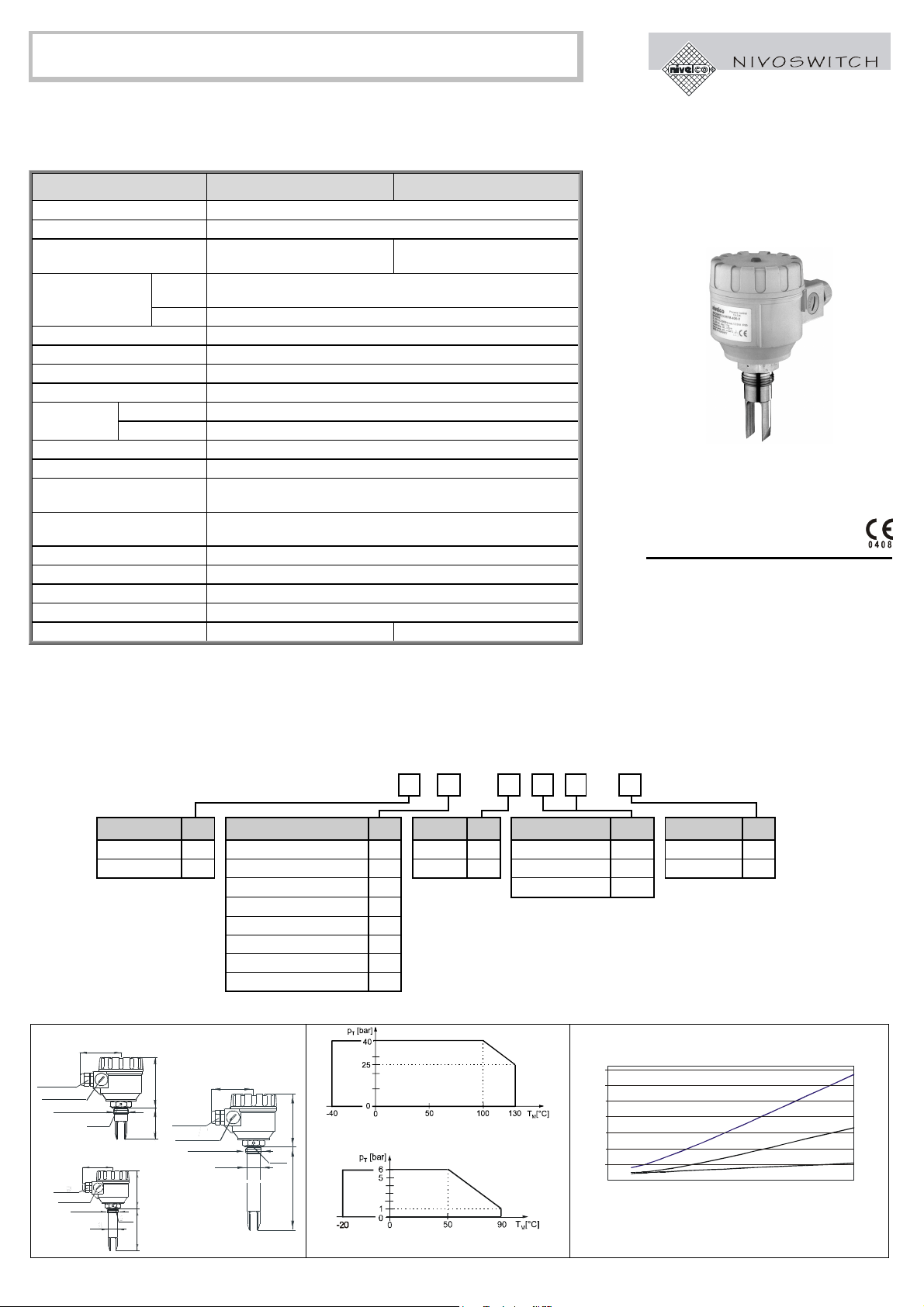
1. APPLICATION
The NIVOSWITCH vibrating forks are for detection of level and flow of liquids. Using them as high or low fail
safe switch overfilling of tanks and dry run of pumps can be prevented.
2. TECHNICAL DATA
MODEL R-400 R-500
Wetted parts St.st. 1.4571 (X 6 CrNiMoTi 17122) or ECTFE (Halar) coated st.st.
Process connection According to the order code
Housing material Aluminium: Powder paint coated Plastic: PBT fibre-glass reinforced,
flame-retardant (DuPont)
Medium -40 °C to +130 °C PP flange: -20 °C to +90 °C
ECTFE coated st.st. flange: -40 °C to +120 °C, for Derating see diagrams
Temperature ranges
Ambient -30 °C to +70 °C
Maximum pressure 40 bar (with PP flange 6 bar) See 2.4 Derating Diagrams
Probe length 69 to 3000 mm
Minimum medium density ≥0.7 kg/dm3
Maximum medium viscosity ≤10000 mm2/s (cSt)
Getting immersed ≤0.5 sec
Response time Getting free ≤1 sec See 2.4 Response Time Diagram
Operation mode indicator Bi-colour LED
Operation mode selection Switch for selection of HIGH or LOW fail safe mode
Output 1 or 2 SPDT relays
Relay 1: 250 V AC, 8 A, AC 1 Relay 2: 250 V AC, 6A, AC 1
Electric connections M 20 x 1.5 cable gland; ∅6 to 12 mm cables
(0.75 to 2.5 mm2wire cross section)
Supply voltage 20 ... 255 V AC and 20 ... 60 V DC
Consumption AC: 1.2 … 17 VA ; DC: < 3 W
Electrical protection Class I.
Ingress protection IP 67 (NEMA 6)
Weight 1.3 kg + 1.2 kg/m 0.95 kg + 1.2 kg/m
WARNING! Temperature difference between inner and outer surface of the ECTFE coated flanges must not exceed 60
°
C. If necessary,
insulate outer surface of the flange.
Vibrating fork level switches
Series: R-400 / R-500
USER’S MANUAL
2.1 ACCESSORIES
−User’s manual – Sealing 2 mm thick made of KLINGER OILIT (for 1” BSP process connection only)
−Warranty Card – Plug-in type, 3-pole terminal block (2 pcs for standard and 3 pcs for models with 2 relay)
−Declaration of conformity –Cable gland M 20 x 1.5 (2 pcs)
2.2 ORDER CODE
NIVOSWITCH R – –
FORK CODE CONNECTIONS CODE HOUSING CODE LENGTH CODE OUTPUT CODE
ECTFE coated D1” BSP thread MAlu. cast 4Short (69 mm) 00 1 Relay 0
Standard F1” NPT thread PPlastic 5Standard (125 mm) 01 2 Relay A
DIN DN50PN40 st.st flange G0.2 to 3 m 02…30
2” ANSI st.st. flange B
50A JIS st.st flange K
DIN DN50 PN16 PP flange F
2” ANSI PP flange A
50A JIS PP flange J
2.3 DIMENSIONS 2.4 Derating DIAGRAMS 2.5 RESPONSE TIME - MEDIUM VISCOSITY
Short model
2xM20x1.5
2 x NPT1/2"
1" BSP
1" NPT
89
S=41
69111
Standard model
89
2xM20x1.5
2 x NPT1/2"
1" BSP
1" NPT S=41
111
125
28
Pipe extended model
89
2xM20x1.5
2x NPT1/2"
1" BSP
1" NPT 28 S=41
111
0.2 ... 3 m
for all models (except PP flanged)
for models with Polypropylene flange
0
5
10
15
20
25
30
35
02000 4000 6000 8000 10000
fullyimmersed
halfimmersed
onlytheflatpartofthetinesimmersed
Kinematic viscosit
[cSt]
Response time
The test was performed using
silicone oils with different viscosity
Response time (when getting free) versus medium viscosity


