manuals.online logo
Brands
  1. Home
  2. •
  3. Brands
  4. •
  5. NIVELCO
  6. •
  7. Switch
  8. •
  9. NIVELCO NIVOPOINT MR Series User manual

NIVELCO NIVOPOINT MR Series User manual

This manual suits for next models

3

Other NIVELCO Switch manuals

NIVELCO NIVOSWITCH R-400 Series User manual

NIVELCO

NIVELCO NIVOSWITCH R-400 Series User manual

NIVELCO MR Series User manual

NIVELCO

NIVELCO MR Series User manual

NIVELCO NIVOCONT R Series User manual

NIVELCO

NIVELCO NIVOCONT R Series User manual

NIVELCO NIVOMAG MK-21 Series User manual

NIVELCO

NIVELCO NIVOMAG MK-21 Series User manual

NIVELCO NIPRESS DK-300 Assembly instructions

NIVELCO

NIVELCO NIPRESS DK-300 Assembly instructions

NIVELCO NIVOSWITCH R-400 Series User manual

NIVELCO

NIVELCO NIVOSWITCH R-400 Series User manual

NIVELCO Nivocap CK User manual

NIVELCO

NIVELCO Nivocap CK User manual

NIVELCO NIPRESS DK-500 Assembly instructions

NIVELCO

NIVELCO NIPRESS DK-500 Assembly instructions

NIVELCO NIVOFLIP MAK-200 User manual

NIVELCO

NIVELCO NIVOFLIP MAK-200 User manual

NIVELCO NIVOSWITCH R-400 User manual

NIVELCO

NIVELCO NIVOSWITCH R-400 User manual

NIVELCO R-400 User manual

NIVELCO

NIVELCO R-400 User manual

NIVELCO NIVOFLIP MAK-100 Series User manual

NIVELCO

NIVELCO NIVOFLIP MAK-100 Series User manual

NIVELCO NIVOCONT K User manual

NIVELCO

NIVELCO NIVOCONT K User manual

NIVELCO NIVOFLOAT NW-100 Series User manual

NIVELCO

NIVELCO NIVOFLOAT NW-100 Series User manual

NIVELCO NIVOPOINT User manual

NIVELCO

NIVELCO NIVOPOINT User manual

NIVELCO NIVOSWITCH R-2 Series User manual

NIVELCO

NIVELCO NIVOSWITCH R-2 Series User manual

NIVELCO NIVOSWITCH R-400 Series User manual

NIVELCO

NIVELCO NIVOSWITCH R-400 Series User manual

Popular Switch manuals by other brands

SMC Networks SMC6224M Technical specifications

SMC Networks

SMC Networks SMC6224M Technical specifications

Aeotec ZWA003-S operating manual

Aeotec

Aeotec ZWA003-S operating manual

TRENDnet TK-209i Quick installation guide

TRENDnet

TRENDnet TK-209i Quick installation guide

Planet FGSW-2022VHP user manual

Planet

Planet FGSW-2022VHP user manual

Avocent AutoView 2000  AV2000BC AV2000BC Installer/user guide

Avocent

Avocent AutoView 2000 AV2000BC AV2000BC Installer/user guide

Moxa Technologies PT-7728 Series user manual

Moxa Technologies

Moxa Technologies PT-7728 Series user manual

Intos Electronic inLine 35392I operating instructions

Intos Electronic

Intos Electronic inLine 35392I operating instructions

Cisco Catalyst 3560-X-24T Technical specifications

Cisco

Cisco Catalyst 3560-X-24T Technical specifications

Asante IntraCore IC3648 Specifications

Asante

Asante IntraCore IC3648 Specifications

Siemens SIRIUS 3SE7310-1AE Series Original operating instructions

Siemens

Siemens SIRIUS 3SE7310-1AE Series Original operating instructions

Edge-Core DCS520 quick start guide

Edge-Core

Edge-Core DCS520 quick start guide

RGBLE S00203 user manual

RGBLE

RGBLE S00203 user manual

Thrustmaster FLIGHT SIMULATOR X quick guide

Thrustmaster

Thrustmaster FLIGHT SIMULATOR X quick guide

Southwire SURGE GUARD 41390 RVC troubleshooting guide

Southwire

Southwire SURGE GUARD 41390 RVC troubleshooting guide

Buhler Nivotemp NT 61 Brief instructions

Buhler

Buhler Nivotemp NT 61 Brief instructions

Kramer VS-41HDCP user manual

Kramer

Kramer VS-41HDCP user manual

Techly IDATA AU-270 user manual

Techly

Techly IDATA AU-270 user manual

Belkin F1U109 user manual

Belkin

Belkin F1U109 user manual

manuals.online logo
manuals.online logoBrands
  • About & Mission
  • Contact us
  • Privacy Policy
  • Terms and Conditions

Copyright 2025 Manuals.Online. All Rights Reserved.

NIVOPOINT
Manufacturer
H-1043 Budapest, Dugonics u. 11.
Phone: (36-1) 889-0100 Fax: (36-1) 889-0200
NIVELCO Process Control Co.
E-mail: sales@nivelco.com www.nivelco.com
OBAC14ATEX0223X

mra1053a0600h_08

1/2
Thank you for choosing a NIVELCO instrument.
We are sure that you will be satisfied throughout its use.
1. APPLICATION
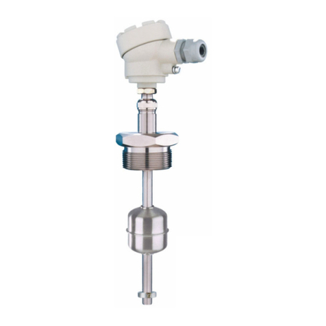
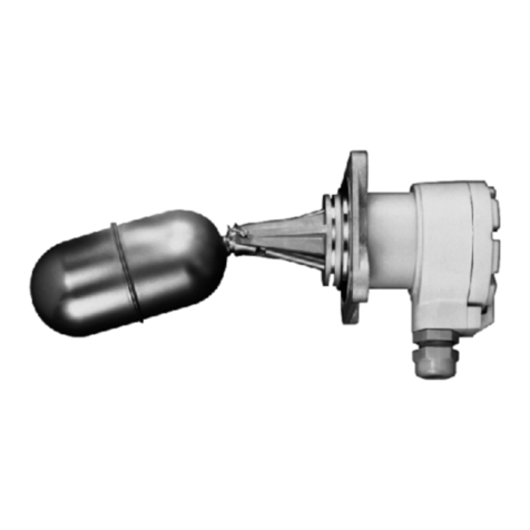
The interaction of the magnetic float and the reed relays (incorporated in the protection tube) is the basis of
the NIVOPOINT magnetic float level switch series operation. They are suitable for level indication of normal
and explosive liquids, and can be used for level control tasks. The protecting tube contains a max. of 5
relays. Parts of the instrument are: probe tube with magnetic float and housing containing the connection
terminal.
The magnetic float moves alongside the protection tube tracking the level of the liquid and activating the reed
relays. As the float passes a relay it changes the output state of the relay which retains this state latching
until the level decreases and the float moves again along the respective relay to switch its state back.
2. TECHNICAL DATA
2.1. GENERAL DATA
TYPE MR – MP– 
MR–
-7
Ex
MR–
-8
Ex
Insertion length 0.25 m ... 3 m
Material of wetted parts Stainless steel
(1.4571 / BS 316Ti)
PVDF float / PFA coated
probe
Stainless steel
(DIN 1.4571 / BS 316Ti)
Max. process pressure 2.5 MPa (25 bar) at +20 C 0.3 MPa (3 bar) at +20 C 2.5 MPa (25 bar) at +20 C
Medium density min.
0.8 kg/dm3
min.
0.5 kg/dm3 min. 0.7 kg/dm3min. 0.8 kg/dm3
Nominal float
dimensions / shape
52x59mm*
cylinder
96 mm*
ball
76x87 mm
cylinder
52x59 mm
cylinder
Medium temp. range -40 °C ... +150 °C -40 °C ... +80 °C
Ambient temp. range -40 °C ... +100 °C -40 °C ... +100 °C See temperature classes table
Output 1 ... 5 pcs reed-switches, connecting one side of each, NO/NC
Switching rate 120 W / VA, 250 V AC/DC, 3 A /reed relay, max. 9 A
Switch differential < 10 mm
Distance of switches min. 110 mm
M20 x 1.5 for cables 6 … 12
M20 x 1.5
for cables
9.5 … 10
M 20 x 1.5
(see: 5.1)
Electrical connection
terminal, wire cross section: 0.5 … 2.5 mm2
Process connection 1” BSP, 2” BSP
1” NPT, 2” NPT
PP flange
DN 80, DN 100
1” BSP, 2” BSP
1” NPT, 2” NPT
Sealing material Klingerit 400 — Klingerit 400
Electrical protection Class I, Protecting cable 4 mm2
Ingress protection IP 65
Ex marking — II 2G Ex d IIC T6 …T3 Gb
Dimension of the hous. 116 x 80 x 65 mm 124 x 80 x 65 mm
Mass 0.4 kg + 0.3 kg/fm 0.45 kg + 0.3 kg/fm
* dimensions of the float depend on the order
Note: the device must be installed with Ex d certified explosion-proof cable gland.
2.2. ADDITIONAL DATA FOR EX APPROVED MODELS
CLASS T6 T5 T4 T3
Max. ambient temperature from –20 °C +80 °C +95 °C +85 °C +70 °C
Max. medium temperature from –20 °C +85 °C +100 °C +135 °C +150 °C
2.3. ACCESSORIES
User’s Manual
Certificate of Warranty
Declaration of Conformity
1 pc Gasket (for threaded versions)
2.4. ORDER CODE
NIVOPOINT M – – ***
TYPE CODE PROCESS CONNECTION CODE SWITCH POINT CODE LENGTH CODE LENGTH CODE FLOAT /EXCODE
Standard R 1” BSP A 1 pc. NO/NC 1 0 m 0 0 m 0 *** / normal 3
2” BSP C 2 pcs. NO/NC 2 1 m 1 0.1 m 1
Standard / plastic
coating and float P 1” NPT D 3 pcs. NO/NC 3 2 m 2 : :
52
1.4571 / Ex 7
2” NPT G 4 pcs. NO/NC 4 3 m 3 0.8 m 8 52
DN 80 PN 16 PP P 5 pcs. NO/NC 5 0.9 m 9 1.4571 / Ex
DN 100 PN 16 PP R without
Notes: cable gland
8
** The order code of an Ex version should end in ’Ex’ *** Depends on the order:

52 / 1.4571, 96 /1.4571 MP version: 76 / PVDF
2/2

OBAC14ATEX0223X

mra1053a0600h_08
2.5. DIMENSIONS
STANDARD VERSION MR- EX VERSION MR- STANDARD VERSION MP- TERMINAL BOX
~7
5
~1 75-230
min. 100
min. 118
L4
L3
L2
L1
Probe leng th
mi n.
110
mi n.
95
mi n.
113
"2 BSP/NPT
96
127
Ø9 6
±25 mm
"1 BSP/NPT
Ø1 24
~7
8
±25 mm
L5
min. 85
L4
L3
L2
L1
Probe leng th
mi n.
110
mi n.
80
~1 95,9 max. (-50 mm)
"2 BSP/NPT
"1 BSP/NPT
60
Ø5 3,5
~7
5
min. 1 30 mm
±25 mm
mi n. 95
L5
L4
L3
L2
L1
Probe leng th
mi n.
110
mi n.
90
Ø7 6
87
DN80
DN10 0
12345C
LEVEL
NO
NC
3. INSTALLATION
For mounting the unit 1", 2" BSP or NPT threads can be used. Minimal gap
diameter for the float is 55 mm. Use the M20x1.5 cable gland for electrical
connection.
The only version that can be installed without removing the float from the shaft
and reassembling it from the inside of the tank is the version with 2” (BSP or
NPT) process connection. If protection tube is used the minimum tube diameter
should be 75 mm (for insertion lenght < 1.5m and 95 mm for insertion
length > 1.5m). When using a 90 mm float the tube diameter should be min.
130 mm.
WARNING!
The sliding sleeve must not be loosened in tanks under pressure.
The unit should be mounted in vertical position via its process connection and
handled with care to avoid any damage or bend of the protection tube during
transportation or installation.
4. WIRING
Depending on the grounding system either the inner or the outer grounding
terminal should be connected to the EP network.
Standard version
Remove the cover. Feed the electrical cables through the cable gland and
connect them in accordance with the sketch on the cover where the (NO/NC)
states of the relays are marked. The terminal of the lowest switch point has to
be number 1.
„C” is common terminal.
The cross section of the connecting cable has to be between 0.5 and 2.5 mm2.
Ex version
Remove the safety clamp and screw the cover off. Feed the electrical cables
through the cable gland and connect them in accordance with the sketch on the
cover where the (NO/NC) states of the relays are marked.
Connect the grounding screw to the grounding system. Place the cover back
and fasten the safety clamp by setting it into one of the notches of the cover.
5. SET UP, ADJUSTMENT
After screwing in and before tightening the sliding sleeve the direction of the
cable gland and the position of the reed-relay set can be adjusted.
An open-end wrench should be used when loosening or screwing tight the
sliding sleeve. The position of the reed-relay set can be vertically adjusted by a
max. of 25 mm.
5.1. SPECIAL CONDITIONS OF THE EX APPLICATION
The apparatus met the requirements specified for mechanical strength with
reduced impact energy (4 J = 1 kg; 0.4 m). On the basis of the above the place
and way of installation should guarantee the protection of the unit against
external mechanical impacts during service.
Before the installation of the device it must be equipped with a certified cable
gland with Ex d protection type. Prior to installing the Ex d certified cable gland
the red protection cap should be removed.
6. MAINTENANCE, REPAIR
The unit does not require regular maintenance. In some instances, however, the
probe may need occasional cleaning to remove surface deposits. This must be
carried out gently, without harming the probe.
All repairs will be carried out at the manufacturer’s premises.
7. STORAGE CONDITIONS
Ambient temperature: -20 °C ... +60 °C
8. WARRANTY
NIVELCO provides warranty of 3 (three) years in compliance with details
described in the Warranty Card.
mra1053a0600h_08
March, 2015
Nivelco reserves the right to change technical specifications without notice.