NKE GYROPILOT 3 User manual
1
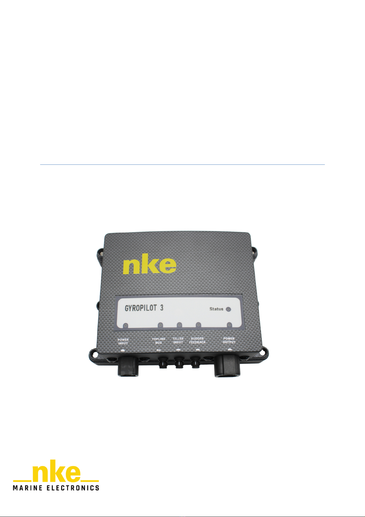
GYROPILOT 3
PROCESSOR
User Manual
This manual describes the installation and initialization of the GyroPilot 3 driver and
explains its operation and settings.

2
Contents
1. Introduction ..................................................................................................................................... 4
1.1. Operating principle of the GyroPilot 3 calculator ................................................................... 4
1.2. Functionalities ......................................................................................................................... 4
2. Installation ....................................................................................................................................... 5
2.1. Equip ent supplied................................................................................................................. 5
2.2. Processor orientation .............................................................................................................. 5
2.2.1. Auto atic detection of the case orientation .................................................................. 5
3. Configuration ................................................................................................................................... 6
3.1. Connection .............................................................................................................................. 6
3.2. Equip ent configutation ......................................................................................................... 7
3.2.1. The type of rudder angle ................................................................................................. 7
3.2.2. The type of hydraulic ra ............................................................................................... 9
3.2.3. The type of circuit supply clutch (PWM/DC) ................................................................... 9
3.3. Rudder initialisation ................................................................................................................ 9
3.3.1. Results of the rudder initialisation ................................................................................ 10
3.4. Pilot speed reference ............................................................................................................ 10
4. Operation ...................................................................................................................................... 11
4.1. The ain odes .................................................................................................................... 11
4.1.1. Rudder ode ................................................................................................................. 11
4.1.2. Co pass ode .............................................................................................................. 11
4.1.3. Apparent Wind ode .................................................................................................... 13
4.1.4. True Wind Mode............................................................................................................ 13
4.1.5. GPS ode ...................................................................................................................... 14
4.1.6. Polar ode .................................................................................................................... 14
4.2. The Super odes ................................................................................................................... 14
4.2.1. Heel angle ode ............................................................................................................ 15
4.2.2. Gust ode ..................................................................................................................... 15
4.3. The Tiller ................................................................................................................................ 15
4.4. Autopilot settings .................................................................................................................. 16
4.4.1. Autopilot gain ................................................................................................................ 16
4.4.2. Rudder coefficient ......................................................................................................... 16
4.4.3. The counter rudder ....................................................................................................... 16
4.4.4. Wind s oothing ............................................................................................................ 16

3
4.4.5. Tacking angle ................................................................................................................. 16
4.4.6. Tacking velocity ............................................................................................................. 17
4.4.7. Man Overboard (MOB) .................................................................................................. 17
4.4.8. Speed reference ............................................................................................................ 17
4.4.9. Ti e before cut-off ....................................................................................................... 17
4.4.10. Rudder offset ................................................................................................................. 17
4.4.11. Dead angle ..................................................................................................................... 17
4.4.12. Setting of the autopilot alar s ...................................................................................... 17
4.5. Tacking ................................................................................................................................... 18
4.6. MOB ....................................................................................................................................... 18
4.7. Downgraded odes .............................................................................................................. 18
4.8. Alar delay ................................................................................................................................. 18
5. Evolution of the processor ............................................................................................................ 20
5.1. GyroPilot2 / GyroPilot3 i prove ent .................................................................................. 20
6. Specifications ................................................................................................................................. 21
6.1. Technical specifications ......................................................................................................... 21
6.2. Default values ........................................................................................................................ 21
7. Liability .......................................................................................................................................... 23

4
1.1. OPERATING PRINCIPLE OF THE GYROPILOT 3 PROCESSOR
The GyroPilot 3 processor is an aid to navigation and is designed to automatically maintain
a course, ensure the boat's stability, assist the skipper during manoeuvres and can put the
boat in a safe position if a man overboard is detected.
Each of these actions can be customised to adapt the operation of the GyroPilot 3 processor
to suit the user's expectations and needs.
When you switch it on, it is necessary to power up the autopilot BEFORE starting
the system, otherwise the autopilot will not be recognised on the installation.
1.2. FUNCTIONALITIES
The GyroPilot 3 processor offers several steering modes to automatically maintain a
course:
- The steering mode
- The compass mode
- The Apparent Wind mode
- The True Wind mode
- The GPS mode
- The Polar mode
The processor also integrates control overlays called "SUPER" modes:
- gust mode
- heel mode
By using the GyroPilot 3 "Pilot Settings" menu, it is possible to customise various parameters
that affect:
- The reaction time and precision of the steering
- The execution of manoeuvres such as instruction changes, tacking, gybe, etc.
- Management of downgraded modes in the event of a malfunction
The GyroPilot 3 processor can be installed in different environments without requiring any
hardware modification: different types of hydraulic ram, rudder angle and clutch.
1. INTRODUCTION

5
2.1. EQUIPMENT SUPPLIED
The GyroPilot 3 processor is supplied in its packaging with a GyroPilot 3 bus cable
90-60-550, a GyroPilot 3 Power Input cable 90-60-553 and a Gyro3 Actuator 1X cable 90-
60-554
2.2. PROCESSOR ORIENTATION
The pilot constantly checks the orientation of the case. The objective is to ensure that it is
always oriented with the connectors facing down, that it has not become unhooked from its
location, or is not incorrectly positioned, so as to enable steering.
If this is not the case, the autopilot will trigger the autopilot alarm.
The pilot also checks the coherence of the roll and pitch it receives from an external attitude
sensor if there is one. The pilot is able to check the correct attitude coherence and to detect
whether an attitude sensor is upside down. In effect, on some boats, compasses are simply
fixed with a glued or a scratch plate bracket. The pilot will quickly detect whether it can be
used for steering. In the event of a sensor inclination that is more than 25° in relation to the
vertical position of the processor, the autopilot triggers an alarm indicating:
•A problem with the mounting of the case if the autopilot has the steepest inclination.
•A problem regarding the mounting of the external attitude sensor if the steepest
inclination is that of the external attitude sensor.
2.2.1. Automatic detection of the case orientation
To use the full functionality of the autopilot, it is important to align the marking on the case
with the marking on the boat.
Four positions are permitted:
•The front of the case facing the starboard side of the boat
•The front of the case facing the port side of the boat
•The front of the case facing the bow of the boat
•The front of the case facing the stern of the boat
During the first commissioning of the autopilot, the processor considers that it has no set
orientation. It will take a few minutes to estimate the orientation of the case if the boat heels
more than 6°. Once the orientation of the case is determined, the autopilot will be able to use
2. INSTALLATION

6
the attitudes to fine-tune the steering set-up and ensure that the loss of sensor information is
minimised in the event of a problem.
During the next few navigation periods, the autopilot will confirm the orientation of the case at
each start-up. As long as confirmation is not obtained, it relies on the old orientation found, to
be able to use the full functionality of the autopilot within the first seconds.
3.1. CONNECTION
3. CONFIGURATION
Rudder angle
sensor
Tiller
Actuator
Junction box
GyroPilot 3
nke

7
3.2. EQUIPMENT CONFIGURATION
Once the GyroPilot 3 is properly installed and connected to the system, several settings are
required prior to use:
•Setting the type of hydraulic ram
•Setting the type of clutch
•Setting the type of rudder angle
•Carrying out a steering initialisation
The GyroPilot 3 can control different types of servo systems: either CFP (Continuous Flow
Pump) or RP (Reversible Pump). It only requires user action on a nke display and does not
need any intervention on the installation.
In the "Pilot" menu of the display, select "maintenance" and then one of the following 3
menus:
•The type of hydraulic ram
•The type of circuit supply clutch
•The type of rudder angle
Caution: any change to the configuration resets the rudder system. The pilot will no longer
operate without a new rudder system initialisation. Starting the autopilot without prior
initialisation will activate a message requesting an initialisation.
3.2.1. The type of rudder angle
There are two types of rudder angle sensors that can be connected to the GyroPilot 3: The
nke rotary sensor or an analog linear sensor.
nke rotary rudder angle:
The sensor should be mounted in parallel with the rudder stock or false rudder stock. For the
sensor to measure the rudder angle correctly, one degree of rudder rotation = one degree of
sensor rotation. This requires that R1 = R2 = 10 cm and that D1 = D2 (see diagram below).
This is called a perfect parallelogram.

8
Picture1: installation of a nke rotary rudder angle sensor
Once the nke rotary rudder angle sensor is correctly installed, the measurement of one
degree of rudder rotation will be automatically converted by the GyroPilot 3 calculator into
one degree of rudder in the autopilot.
Analog linear rudder angle:
The GyroPilot 3 system also integrates linear rudder angles. To take such a sensor into
account, it is necessary to measure the triangle of the steering system (see picture below). 5
measures are required:

9
•Center R - rudder to amidship: distance in mm between the rudder stock axle and
the sensor mounting on the tiller arm
•Center L - rudder to amidship: distance in mm between the rudder stock and the
sensor fastening to the boat
•Center X - rudder to amidship: size of the linear sensor (mm) corresponding to a
centred rudder
•Starboard X - rudder to starboard: size of the linear sensor (mm) corresponding to
the starboard stop position of the rudder
•Port X - rudder to port: size of the linear sensor (mm) corresponding to the port stop
position of the rudder
Once these measurements have been completed, they must be entered in the "Measures"
menu. To do this, the " rudder sensor " option must be changed to linear rudder. If this has
not been done, then the " Measures " menu will be available just below.
Note: These measurements should be done before the rudder initialisation is completed. The
same positions should be used during the rudder initialisation (rudder amidships, rudder to
the starboard stop position and rudder to the port stop position). This is why it is necessary to
take the most accurate benchmarks as possible.
3.2.2. The type of hydraulic ram
The GyroPilot 3 processor allows you to choose in the "Pilot-Maintenance" menu, the type of
hydraulic ram used.
3.2.3. The type of circuit supply clutch (PWM/DC)
The type of clutch used can be selected by the user in the "Pilot-Maintenance" menu.
3.3. RUDDER INITIALIZATION
The rudder initialisation is a procedure to take into account the settings needed to detect
the direction of movement of the hydraulic ram and the rudder angle sensor. A wizard on the
nke displays allows this procedure to be carried out. It is divided into 4 steps:
•Step - rudder to amidship: used to determine the 0° of the rudder angle.
•Step - rudder to starboard end position: sets the maximum rudder limit for heading
to starboard. It also detects the direction of movement of the rudder angle sensor.
•Step - rudder to starboard end position: enables setting of the maximum rudder
limit for heading to port.
•Step - activation of the hydraulic ram: the hydraulic ram activates automatically. It
moves the rudder in one direction and then comes back to the amidship position.
This allows the autopilot to determine the polarity in order to go to one side or the
other.

10
3.3.1. Results of the rudder initialisation
Once initialisation has been completed, the autopilot sends the status of the rudder
initialisation to the displays
If the initialisation has been successfully completed,
•The measured rudder-stop information and rotation speed are displayed
•The LED of the rudder angle sensor lights up in green
•The autopilot changes the rudder angle status to "valid" and the autopilot becomes
operational.
If the procedure is invalid
•The display will show: "Invalid rudder initialisation".
•The LED of the rudder angle sensor will remain orange
•The autopilot sets the rudder angle status to "invalid" and the autopilot remains
disabled.
In the case of an invalid procedure, the whole procedure must be carried out again. Rudder
initialisation can be considered invalid in the following cases:
•The rudder angle sensor sends incorrect or missing information. The rudder angle
sensor is immediately discarded and the rudder initialisation fails.
•The starboard and port rudder stops are within 4 degrees of each other. The
amplitude of the rudder crosshead is too small for optimal use.
•The zero of the rudder is outside the range [starboard rudder stop, port rudder stop]
(rudder stops have the same sign). In this case the initialisation procedure fails.
•The hydraulic ram cannot move the rudder faster than 0.2°/s. In this case, it considers
that the hydraulic ram is not responsive enough and that the autopilot cannot be used
efficiently.
3.4. PILOT SPEED REFERENCE
The speed used by the autopilot can result from different possible sources: GPS, nke
SPEEDO. These elements provide the true speed and/or the ground speed of the boat.
Based on all this information, it calculates the autopilot speed which is the boat speed data
that the autopilot will consider. For the GyroPilot 3, the speed used by the autopilot is only a
selection of the speed source (ground or surface) chosen by the skipper via a nke display.

11
4.1. THE MAIN MODES
The steering modes available for the GyroPilot 3 processor can be selected from the
"Pilot" menu and then "Mode select" or from a pilot page by pressing the OK button and then
"Mode select".
The GyroPilot 3 processor has a total of 6 steering modes, but a display will only show
the modes that can be used with the sensors available on the installation. If, for example,
there is no wind speed/wind vane sensor, the wind modes will not be available. Only the
rudder angle sensor is needed in all steering modes
-The rudder mode: requires a rudder angle sensor connected to the processor and
configured.
-The compass mode requires heading data
-The Apparent Wind mode requires a wind speed/wind vane sensor.
-The True Wind mode requires a wind speed/wind vane sensor and boat speed data.
-GPS mode requires a compass sensor, as well as a GPS, or any other instrument that
sends NMEA GPS sentences. The latter must be connected to an NMEA input on the
nke installation.
-The polar mode requires an external processor that provides the optimal wind angle
(VMG) calculated from a speed polar.
4.1.1. Rudder mode
The rudder mode is the most basic mode of the autopilot. The set value is a rudder
angle. The rudder mode allows you to set a rudder angle and lock the rudder at the selected
value. The pilot gives the selected rudder angle as a set value, within the limits of the stops
detected during the rudder initialisation procedure. This mode is a distinct mode because it
acts directly on the steering circuit.
Note: This mode is very useful when looking for a malfunction. If the mode is operating, the
possibility that the hydraulic ram or the rudder angle is the cause of the problem is excluded.
4.1.2. Compass mode
In compass mode, the GyroPilot 3 processor steers the boat by following the magnetic
heading given by the compass.
The compass mode screen below is displayed on a multi-display:
4. OPERATION

12
-The set value indicates the reference heading to be reached, selected by the user. This
screen displays "---" or "OFF" when the autopilot is disengaged.
-The steering mode reference indicates the current course of the boat; it is the magnetic
heading channel,
-The pilot gain window is common to the six modes.
-The rudder angle indicator is common to the six modes.
To use the Compass mode at sea:
-Select "Compass" in the steering mode.
-Steer your boat and press the Auto button to activate the GyroPilot 3.
-The pilot then takes the heading as a reference. The GyroPilot 3 is then activated and
steers the boat.
-You can use the +/-1 and +/-10 keys on a PAD, a remote control or a display to adjust the
set-point.
-To switch off the GyroPilot 3, take over the steering and press the stop button.
WARNING
:
The Auto button is used to activate the autopilot, i.e. to turn it on.
The Stop button is used to deactivate the autopilot, i.e. to turn it off.
Pilot ode reference
Rudder angle
indicator
Pilot ode
Course to steer
Gain value

13
4.1.3. Apparent Wind mode
In apparent wind mode, the GyroPilot 3 steers the boat by following the apparent wind
angle, given by the wind speed and wind direction sensor. It is mainly used upwind. The
page displayed is identical to that of the compass, except that the steering mode label is
replaced by the apparent wind angle.
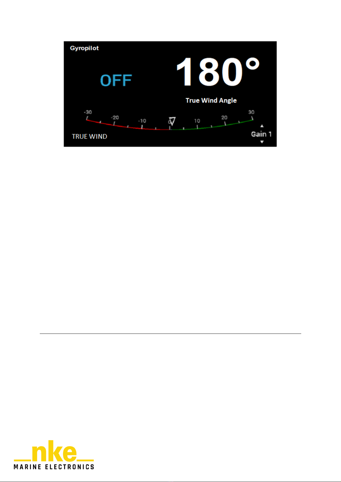
4.1.4. True Wind Mode
In true wind mode, the GyroPilot 3 steers the boat according to the true wind angle given
by the system.
Why use the True Wind mode?
The true wind mode is particularly effective when sailing downwind in heavy swell: In these
conditions, the GyroPilot 3 shows its potential. If you use the apparent wind mode
downwind and in swell, you will observe this:
-As the boat descends the wave, the apparent wind speed increases, the apparent wind
angle decreases and therefore, the wind heads. Action of the autopilot: it makes the boat
bear away.
-As the boat climbs the wave, the apparent wind speed decreases, the apparent wind
angle increases and therefore the wind lifts. Action of the autopilot: it makes the boat luff
up.
In swell, the apparent wind mode does not allow for perfect heading control and you have to
switch to compass mode to descend the wave with a straight trajectory.
The true wind mode allows you to go straight down the wave and keep the optimum
descending angle. The true wind angle does not vary with boat speed.
14
4.1.5. GPS mode
In GPS mode, the GyroPilot 3 steers the boat by following the route given by the GPS. To
do this, a GPS or other instrument that delivers NMEA GPS sentences must be connected to
an NMEA input on your installation.
-A graph shows the cross track error, the XTE.
-CTW (Course to Waypoint), COG (Course Over Ground in °), DTW (Distance to
Waypoint in Km or M), SOG (Speed Over Ground in Km/h or knt) and XTE (in Km or NM
information is displayed.
The GyroPilot 3 processor follows the route to the Waypoint. On arrival at WAYPOINT <
0.1NM, the NKE displays beep and the autopilot switches to compass mode. If the user
enters a new waypoint, the GyroPilot 3 automatically switches back to GPS mode.
4.1.6. Polar mode
The polar mode enables the boat to follow an optimal wind angle. This angle is the best
upwind angle when heading into the wind: VMG up, or the best angle when heading down
the wing in downwind conditions: VMG down. Apart from the set-point change in relation to
the wind speed, this mode functions like a true wind mode.
4.2. THE SUPER MODES
The SUPER modes are used in addition to the main modes. They allow the autopilot's set
point to be adjusted slightly in response to a temporary phenomenon: heel variation, gust
In the GyroPilot 3, only one SUPER mode can be activated at one time. There are 3 states in
a SUPER mode:
•Status: OFF. The skipper has not selected SUPER mode.
•Status: Standby. SUPER mode is ready to be used, but it is not active yet:
oa piece of data is missing,
othe autopilot is not activated,

15
othe SUPER mode has deactivated itself due to a manoeuvre or change in the
main mode.
•Status: ON. The SUPER mode is activated
4.2.1. Heel angle mode
This mode allows you to maintain a constant heel angle. It can be activated when
following a set-point in compass, apparent wind, true wind or polar mode. This mode can be
set on the displays:
•Leeward limits: maximum leeward set point deviation in degrees that the skipper
allows to follow the heeling angle instruction
•Windward limits: maximum windward set point deviation in degrees that the skipper
allows to follow the heeling angle instruction
•Gain: value given to the heel angle instruction follow-up. The higher the gain, the less
the autopilot is tolerant to heel angle variations. Caution: a very precise follow-up of
the heel variation can have consequences on the regularity of the boat's trajectory. It
is, therefore, a matter of finding the best gain compromise.
4.2.2. Gust mode
The gust mode allows you to react at the helm during a gust. It can be activated when
following a set-point in compass, apparent wind, true wind or polar mode. This mode can be
set on the displays:
•Limit: the maximum set point variation in degrees that the skipper allows to counter a
gust.
•Gain: value given to counter a gust The higher the gain, the less tolerance the
autopilot has to variations of wind speed and the faster he responds to a gust.
Caution: a very precise follow-up can have consequences on the regularity of the
boat's trajectory. It is, therefore, a matter of finding the best gain compromise.
•Filter: period of time over which the gusts are detected. The larger the time window,
the more the gust mode will react to long gust periods.
4.3. THE TILLER
The tiller is a pilot operating mode using a joystick. To use it, the autopilot must be activated.
If the joystick is activated, the autopilot automatically switches to TILLER mode. If the joystick
is deactivated, the autopilot automatically switches back to the previous mode.

16
4.4. AUTOPILOT SETTINGS
4.4.1. Autopilot gain
The pilot gain allows the boat to be more responsive. Gain increase is often used in the
following circumstances:
•In rough sea conditions, the increase of the gain allows to counter more efficiently the
strong waves which cause lurches.
•When sailing downwind, with powerful sails such as a spinnaker, the increase in gain
helps to avoid excessive set-up variations which can cause into the wind or down the
wind runs.
The setting range is between 1 and 9.
4.4.2. Rudder coefficient
The rudder coefficient controls the amplitude and acceleration of the rudder movements
according to the speed of the boat. Its value is increased in proportion to the speed of the
boat.
The setting range is between 1 and 53.
4.4.3. The counter rudder
The counter rudder prevents trajectory fluctuations from occurring around the set point. The
boat's motion expectation is preset. Anticipation is necessary in the following cases:
•Boats with high inertia. Naturally, the counter-rudder value will be high
•The delay of pilot data is sometimes intentional for filtering reasons
•Trajectory fluctuations around the set point
The setting range is between 1 and 9.
4.4.4. Wind smoothing
Wind smoothing is used in apparent wind, true wind or polar mode. This setting is used to
stabilise the steering when the wind measurement fluctuates. The setting range is between 1
and 9.
4.4.5. Tacking angle
This is the auto-tacking angle in compass mode, adjustable from 70 to 115° with increments
of 5°.

17
4.4.6. Tacking velocity
The tacking speed is adjustable from 1° to 32°/s.
4.4.7. Man Overboard (MOB)
In the autopilot settings, it is possible to select the "Man Over Board" menu among two sub-
menus: MOB crew and MOB single-handed (see. §MOB )
4.4.8. Speed reference
The speed source is used to select the type of speed that the autopilot will choose to adjust
the servo and to calculate the true wind.
4.4.9. Time before cut-off
There are extremely downgraded configurations in which the autopilot is no longer able to
steer. In this case, the autopilot triggers a pilot alarm and releases the steering after a period
of time: This is "the time before cut-off" if the situation has not changed favourably. The
setting range varies from 20 seconds to 300 seconds.
4.4.10. Rudder offset
There is a rudder offset that can be used in some special circumstances. In the event of
a rudder angle sensor failure, while sailing in difficult conditions, it is often impossible to
perform a rudder initialisation procedure. The rudder offset can, therefore, be used
temporarily to allow steering with a second rudder angle already set. The setting range is
between -3° to 3°.
4.4.11. Dead angle
The dead angle takes into account the mechanical looseness that exists in the steering
systems of boats. The setting range is between 0 and 3°.
4.4.12. Setting of the autopilot alarms
The GyroPilot 3 processor has two configurable alarms
-The wind direction alarm, called "wind/heading", monitors a change in wind direction in
compass mode and a heading change in wind mode.
-The battery voltage alarm, known as the "power battery", monitors the charge status of
the autopilot's battery. The default setting is 10Vdc.

18
4.5. TACKING
The GyroPilot 3 allows you to tack in any mode: compass, apparent wind, true wind or polar.
Tacking or gybing is executed by a long press on the +/-10 key of a pilot control box.
4.6. MOB
The radio transmitter must first be activated in scan mode (see transmitter manual).
Man over board (MOB) is a safety manoeuvre. When the receiver no longer receives
messages from the radio transmitter (this is called a radio loop break), the autopilot initiates a
MOB procedure.
Depending on the settings of the "Man over board" parameter of the autopilot there are 2
procedures:
•Crew mode: the navigation system triggers an audible alarm but does not cause any
steering changes.
•Solo mode: the navigation system triggers an audible alarm and then takes the
control in order to is hove to. It uses all the data available to it to carry out the
manoeuvre as accurately as possible.
4.7. DOWNGRADED MODES
In the event of a sensor failure, the autopilot keeps control of the helm during the "Time
before cut-off" or temporarily changes the steering mode.
In true wind mode, if the wind vane is disconnected from the system, the GyroPilot 3
computer automatically switches to compass mode. If the wind vane is connected again to
the system, the processor will automatically switch back to the selected wind mode.
If the bus is shut down with the autopilot switched on, the autopilot does not disengage the
steering control immediately. It blocks the rudder and waits for the "time before cut-off" to
elapse before handing over. This also applies if the processor bus cable is pulled out.
4.8. ALARM DELAY
Acknowledgement of the alarm is the action carried out by the skipper on a display or remote
control to stop the alarm. When the alarm is acknowledged, a time delay is activated during
which lower priority alarms and of the same type are disabled.

19
Each time the skipper acknowledges the same alarm, the time delay doubles. Thus, an
alarm with a time delay of one hour will be disabled for one hour after the first
acknowledgement, two hours after the second and four hours after the third.

20
5.1. GYROPILOT2 / GYROPILOT3 IMPROVEMENT
•CFP/RP configuration without hardware modification.
•6 LEDs on the front panel to indicate the status of the autopilot.
•New high-performance electronic components.
•Faster algorithm with more accurate steering control.
•Enhanced pilot problem diagnosis.
•Securing of the steering system.
•Improvement of the tacking algorithm.
•Improved MOB algorithm with gybe "heave to" logic and logic for use of all sensors
regardless of the configuration preceding the new order.
•Suppression of the rudder stroke if the rudder angle sensor is no longer available.
•Wind tables are taken into account in the autopilot's calculations.
•Message on bus when none execution of initialisation is detected.
•In case of overload, the processor keeps steering. It limits the intensity to 25A for the
duration of the overload. However, if this lasts longer than 10 minutes, the GyroPilot 3
stops steering.
•Linear rudder sensor management.
•Improved Tiller algorithm with speed feedback control.
•Polar mode.
•Heel angle mode.
•Gust mode.
5. EVOLUTION OF THE PROCESSOR
Table of contents
Other NKE Marine Equipment manuals


Popular Marine Equipment manuals by other brands


Nexus
Nexus NX Sea Data Installation and operation manual

IMCO
IMCO SCX Series Information, Operation and Maintenance

Syqwest
Syqwest HydroBox Installation, operation and maintenance

Furuno
Furuno FMD3100 installation manual

Raymarine
Raymarine i50 Depth Installation and operation instructions

Simrad
Simrad GC80 EXPANDED instruction manual


