NKE CARBOWIND HR Instruction Manual
Zi de Kerandré – Rue Gutemberg – 56700 – HENNEBONT – FRANCE
www.nke-marine-electronics.com
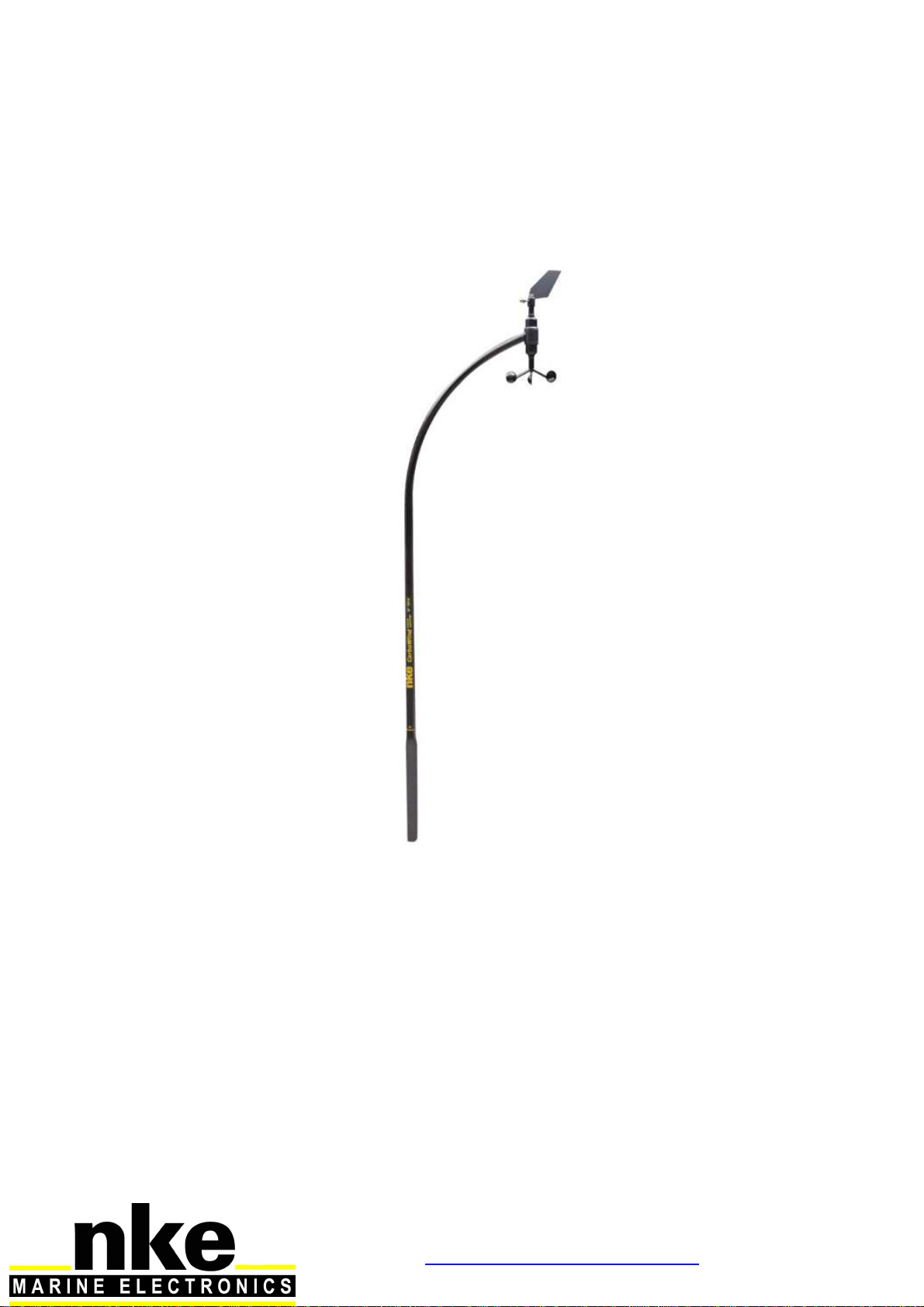
Masthead unit
CARBOWIND HR
Product reference : 90-60-370
USER GUIDE
and
INSTALLATION GUIDE

2
38_Carbowind_HR_um_UK_28
SOMMAIRE
1
USING ..................................................................................................................................................................................3
1.1
P
RESENTATION
..............................................................................................................................................................3
1.2
L
IST OF CHANNELS DISPLAYED
.......................................................................................................................................4
1.3
A
LARMS SETTING
...........................................................................................................................................................4
1.4
F
ILTERING OF THE CHANNELS
........................................................................................................................................5
1.5
C
HOICE OF THE UNIT
......................................................................................................................................................5
1.6
T
ECHNICAL CARATERISTICS
...........................................................................................................................................5
1.7
D
IAGNOSTIC OF
1
ST
LEVEL TROUBLESHOOTING
. .............................................................................................................5
2
CALIBRATION...................................................................................................................................................................6
2.1
C
ALIBRATION OF THE WIND VANE
..................................................................................................................................6
2.2
C
ALIBRATION OF THE ANEMOMETER
..............................................................................................................................7
3
INSTALLATION.................................................................................................................................................................8
3.1
L
IST OF ACCESSORIES
....................................................................................................................................................8
3.2
INSTALLATION
P
R
E
CAUTIONS
........................................................................................................................................8
3.3
F
IXING THE CABON TUBE
...............................................................................................................................................8
3.4
S
ETTING THE HEIGHT OF THE
CARBOWIND
HR..........................................................................................................11
3.5
W
INDMILL MONTING PROCEDURE
................................................................................................................................11
3.6
C
ONNECTING TO TOPLINE BUS
.....................................................................................................................................12
4
MAINTENANCE...............................................................................................................................................................13

3
38_Carbowind_HR_um_UK_28
1 USING
1.1 PRESENTATION
The CARBOWIND HR is a measuring instrument for wind speed and direction. It is connected
to the TOPLINE bus of your installation. Equipped with high quality ball bearings and
mechanical elements of precision, the CARBOWIND HR unit guaranteed qualities of a reliable,
precise and sensitive sensor.
Connect the cable of the CARBOWIND HR directly to the TOPLINE bus box
The CARBOWIND HR is supplied without support and without cable.

4
38_Carbowind_HR_um_UK_28
1.2 LIST OF CHANNELS DISPLAYED
The CARBOWIND HR, connected to the TOPLINE bus of your installation, creates the
channels below. They are then accessible using the displays of the TOPLINE range.
Channel Display Unit
Apparent wind speed WIND SPD / A
0.0Kt m/s or knot
Apparent wind angle WIND ANG / A
0° degree
Air temperature
Air temp 15.4° °C or °F
If your installation is equipped with a speedometer
True wind speed WIND SPD / T
0.0Kt m/s or knot
True wind angle WIND ANG / T
45° degree
If your installation is equipped with a TOPLINE compass
True wind direction WIND DIR / T
300° degree
The apparent wind angle is displayed in degrees : from 0° to -180° on port tack and from 0° to
180° on starboard tack.
1.3 ALARMS SETTING
The setting of an alarm enables you to monitor the value of a channel. When the preset
threshold is exceeded, a warning message is displayed and an audible alarm is activated.
The upper alarm is activated when the display is higher than the programmed threshold.
The lower alarm is activated when the display is lower than the programmed threshold.
To cancel the alarm of a channel, enter the value 0in the upper alarm and the lower alarm.
Thus, the setting of an alarm on the wind speed, wind angle or air temperature channels will
allow you to supervise your installation effectively as well as the good operation of your boat.
To activate alarms, please refer to the user guide of your display
IMPORTANT
-Do not dismantle masthead unit parts
-Read this user guide entirely before starting the installation.
-The electrical connection of the TL25 on the TOPLINE bus must be carried out with
the terminal box 90-60-121. Only use TOPLINE bus cable of the type 20-61-001.
-Any intervention on the TOPLINE bus must be carried out with the installation power
switched off.
-
For channel settings, please refer to your TOPLINE display guide
.

5
38_Carbowind_HR_um_UK_28
1.4 FILTERING OF THE CHANNELS
The level of filtering of a channel determines the frequency of update of the data displayed.
For example, in rough sea when the boat moves significantly, it is useful to increase the filtering
of the speed channel to stabilise the value displayed. Conversely, in calm sea, low filtering will
be preferable to obtain a fast response of the display.
Filtering is adjustable between 1and 32, and the default value is 8. The lower this value is, the
higher the frequency of update is.
Please refer to the user guide of your display to carry out the filter setting.
1.5 CHOICE OF THE UNIT
You have the option to choose the following display units :
-Wind speed : in knots or in m/s.
-Air temperature : in degree Fahrenheit or in degree Celsius
Please refer to the user guide of your display to carry out this change of units.
1.6 TECHNICAL CARATERISTICS
-Power supply : 10 to 16VDC
-Consumption : 25mA
-Wind speed range : tested in laboratory, 0 up to 60 knots.
-Wind speed sensibility: < 2 knots.
-Angular resolution of the anemo wane : 1°
-Air temperature range : -10°C à +50°C
-Tightness :IP67
-Weight : 600g
-Bus cable : Ø 3.0 – weight : 17 g/m.
-Operating temperature : -10°C to +50°C
-Storage temperature : -20°C to +60°C
1.7 DIAGNOSTIC OF 1
ST
LEVEL TROUBLESHOOTING.
Before contacting technical support, please check the troubleshooting table below.
Problem Possible causes and solutions
The Topline installation does not detect the masthead unit.
The bus cable is not or is badly connected to the terminal box : check the
connection inside the terminal box. Check the state of the cables : they
must not show any sign of wear or cut.
The apparent wind speed indicates 0.0, no matter what the wind
speed is. Check that the calibration coefficient is different from 0.0 : refer to §3.
Check that the winch is not blocked.
The apparent wind speed indicates 0.0 and the air temperature
channel indicates « Pan ». It is possible that the masthead unit is disconnected or broken. Check the
state of the cable and the connection to the box.
The apparent wind angle indicates 35° at close haul on one
board and 65° on the other. Check that the stem of the masthead unit follows the axis of the boat
Carry out a calibration of the vane: refer to §3.
If you do not manage to solve the problem, please contact your distributor.

6
38_Carbowind_HR_um_UK_28
2 CALIBRATION
The CARBOWIND HR is adjusted at the factory. However, a calibration is required to adapt the
sensor to the specificities of your boat and to obtain an optimum measurement accuracy.
Follow the calibration procedure below, by visualising the settings on a display : please refer to
the user guide of the display.
2.1 CALIBRATION OF THE WIND VANE
2.1.1 Principle of the calibration
After the masthead unit has been installed, a real test at sea needs to be carried out. You will
sail on port tack and on starboard tack in order to raise the wind angle displayed on the channel
APP WIND ANGLE. Then, you will deduce the offset value which will enable you to adjust the
wind vane. Thus, a calibration rectifies all the shifts that result from an installation at the head of
mast : assembly position (alignment), torsion and inflection of the mast during navigation.
Note that each wind vane is set with a factory offset. This offset ranges between 0° and -180°
or between 0° and +180°. It is the reference of your wind vane in relation to the axis of the
support stem. Before the start of a calibration, we recommend that you make a note of this
value as it may be useful in case of bad handling.
2.1.2 OFFSET setting procedure
To achieve a successful calibration, sail on a calm sea, with a moderate wind.
1. Display the channel APP WIND ANGLE.
2. Sail and follow several close-hauled tacks : note the values of apparent wind angle
displayed.
3. Calculate the average of the values displayed on starboard tack and those displayed on port
tack.
4. Calculate the offset correction : ( average starboard angle -average port angle).
2
5. Adjust the factory offset with the value of offset calculated
Notice: If after these adjustments and in of other conditions of wind, you notice that it exists an asymmetry of the
angle of apparent wind when you tack, this is not the offset one that diverted, but this is the effect of the wind shear.
You will notice that you will not be able to upwind to the same wind angle on the two opposite tacks, and that
outside of the electronics indication. Also to eliminate this shearing effect, it is counseled to adjust the offset one of
masthead unit before every regatta. This shearing can vary during the day.
Example 1 :
Factory OFFSET = 60
Average apparent wind angle starboard tack :45°
Average apparent wind angle port tack :35°
Value to be added to the factory OFFSET = (45°-
35°) / 2 = 5 °
New offset value = 5 +60 = 65
Example 2 :
Factory OFFSET = 60
Average apparent wind angle starboard tack :39°
Average apparent wind angle port tack :45°
Value to be deducted from the factory OFFSET =
(39°- 45°) / 2 = - 3 °
New offset value = 60-3= 57

7
38_Carbowind_HR_um_UK_28
2.2 CALIBRATION OF THE ANEMOMETER
2.2.1 Principle of the calibration
You will adjust the calibration coefficient of the channel apparent wind speed, so that the
speed displayed is equal to the true ambient wind speed.
You can carry out this calibration at port.
2.2.2 Setting procedure of the calibration coefficient
1. Select the calib coef sub-channel of the apparent wind speed channel.
2. Enter the new calibration coefficient and validate using the enter key. The new setting will
be saved to the memory.
CAUTION : The calib coef parameter is a multiplier coefficient. This value must
never be equal to zero. By default this coefficient is set to 1.00. If it is not the case,
before starting a calibration enter the value 1.00.

8
38_Carbowind_HR_um_UK_28
3 INSTALLATION
3.1 LIST OF ACCESSORIES
-Cable Carbowind avionic 25m : 90-60-381
-Cable Carbowind avionic 35m : 90-60-351
-Carbowind Trapezoidal Tube : 90-60-537
3.2 INSTALLATION PRECAUTIONS
The CARBOWIND HR is fixed on the mast head using a carbon trapezoidal tube.
3.3 FIXING THE CABON TUBE
This Trapezoidal tube must be laminated at the top of the mast. The CARBOWIND HR pole is
inserted into this tube and locked in rotation due to this trapezoidal shape.
Note that, the internal diameter of the support tube is perfectly adjusted, so that there is no play
with the CARBOWIND HR pole and that the whip of it does not cause the initiation of rupture.
Warranty conditions
Carbowind HR reference 90-60-370-012 – Carbowind Trapezoidale tube référence 90-60-537
We decided to review the design of the sensor itself and the sleeve to be used for the support.
This sleeve is specific to the Carbowind HR since 2016.
The study of warranty coverage will be done only if the tube reference 90-60-537 is used.
The round inner shape should be mounted upwards.
Grease the bottom of the Carbowind to allow easier extraction.
It is advisable to install a thermo-retractable sheath with glue on the top of the sleeve to seal
the connection.
1. In the case of mounting at the top of the mast.
The sleeve is not structural, it must be consolidated by laminating reinforcement (0 ° fiber
enclosed in a peripheral winding).
For the anti-extraction make a textile shingle attached to a fixed point of the mat head.

9
38_Carbowind_HR_um_UK_28
Please observe the following assembly.

10
38_Carbowind_HR_um_UK_28
2. In the case of mounting on the side of the mat.
It must be stratified over the entire height, leaving 20 to 30 mm free for the installation of a heat-
shrinkable sheath. It is advisable to leave the bottom free to allow the extraction of Carbowind.
For anti-extraction, make a textile bristle fixed on the mast or put a small diameter screw in the
lower part of the sleeve.
20/30 mm
non-stratified
C
U
T
A-
A
A
-

11
38_Carbowind_HR_um_UK_28
3.4 SETTING THE HEIGHT OF THE CARBOWIND HR
The CARBOWIND HR is delivered with a carbon tube with a length of 1.20 meters.
The tube can be shortened in the case of mounting on a mat having the old round sleeve. In
this case the Carbowind cable comes out from the bottom of the tube after having cut it at the
yellow line level. Be careful when cutting the tube not to damage the cable.
3.5 WINDMILL MONTING PROCEDURE
1. Make correspond the flat surface of the windmill with the flat surface of the axis.
2. Insert the windmill on the axis
3. Insert and tight the nut.
Warning :
Be careful not to damage the cable when drilling the hole for the anti rotation which will be
compulsory in this mounting case.

12
38_Carbowind_HR_um_UK_28
3.6 CONNECTING TO TOPLINE BUS
If the cable runs inside the mast, make the cable pass through an opening equipped with a
grommet. If the cable runs across the deck, make the cable pass through a tight stern tube
gland.
1. Make the masthead unit cable run towards the TOPLINE terminal box of your installation.
Connect the bus cable inside the terminal box :
If you reduce the length of the bus cable, strip and tin the wires before connecting them in the
connection box.
BLANC
GND
NOIR
BLANC
GND
NOIR
12V
GND
NMEA-
NMEA+
NMEA-
NMEA+
init
Main suppy 12Vdc
Connecting box
90-60-417
-
GND
DATA black
12VDC white
Figure 3 : conncting to TOPLINE bus
NMEA input
+
init wire
nke
TL 25
16.85
VITES SURF
ANG VENT AP
105-
274°
CAP MAGNET
NOEUDS
DEGRES
DEGRES

13
38_Carbowind_HR_um_UK_28
4 MAINTENANCE
The axes of the wind vane and the anemometer are mounted on ball bearings, and rotate
continuously. If possible, we advise you to disassemble the wind vane from its support, during
wintering periods, to increase the life of the bearings.
If you put down the wind vane, for dismasting or wintering for example, protect the cable plug
to prevent water ingress.
This manual suits for next models
2
Table of contents
Other NKE Marine Equipment manuals


