NKE MULTIDISPLAY User manual

6 Rue Gutemberg - Zi de Kerandré
56700 – HENNEBONT – FRANCE
www.nke-marine-electronics.com
+33 297 365 685
MULTIDISPLAY
Item number: 90-60-543
USER MANUAL
&
INSTALLATION SHEET
V1.1

Page 2/55 68_Afficheur_Multidisplay_um_UK_11
1
PRESENTATION............................................................................................................................ 4
2
USE................................................................................................................................................. 4
2.1
M
ENU
P
AGE
................................................................................................................................................. 5
2.2
P
AGE BUILDING WIZARD
.................................................................................................................................. 6
2.2.1
Page format..................................................................................................................................... 6
2.2.2
Edit a page....................................................................................................................................... 8
2.2.3
Visible ............................................................................................................................................ 10
2.2.4
Edit name ...................................................................................................................................... 10
2.3
D
ISPLAY
P
AGES
........................................................................................................................................... 10
2.4
U
SE OF THE
M
ULT GRAPH C AS MULTIFUNCTION DISPLAY
..................................................................................... 11
2.4.1
Edit an existing page ..................................................................................................................... 11
2.4.2
Temporary modification ................................................................................................................ 11
2.4.3
Permanant modification of a page constructed ............................................................................ 11
2.5
S
ETTING
P
ARAMETERS
.................................................................................................................................. 11
2.5.1
Display Settings ............................................................................................................................. 12
2.5.2
Backlighting ................................................................................................................................... 12
2.5.3
Setting Night and Day modes ........................................................................................................ 12
2.5.4
Skin Settings .................................................................................................................................. 13
2.5.5
Display’s Standby timing ............................................................................................................... 13
2.5.6
Data logging : « stripcharts » settings .......................................................................................... 14
2.5.7
A,B,C,D keys configuration of the multifunction Pad .................................................................... 14
2.5.8
Language selection ........................................................................................................................ 14
2.5.9
Unit selection ................................................................................................................................. 14
2.5.10
Maintenance............................................................................................................................. 15
2.5.10.1
Mu tidisp ay node address in the Top ine system ............................................................................... 15
2.5.10.2
Auxi iary inputs .................................................................................................................................... 16
2.5.10.3
Top ine Instrument system .................................................................................................................. 16
2.5.10.4
Orientation .......................................................................................................................................... 17
2.5.10.5
Keypad Beep ........................................................................................................................................ 17
2.5.10.6
Firmware ............................................................................................................................................. 17
2.5.10.7
Memory ............................................................................................................................................... 17
2.5.10.8
Simu ator ............................................................................................................................................. 17
2.5.10.9
Autotest ............................................................................................................................................... 18
1
2.6
S
ENSOR
S
ETTINGS
.................................................................................................................................. 19
2.6.1 Calibration wizard ............................................................................................................................... 19
2.6.2
Apparent Wind Angle calibration wizard ...................................................................................... 19
2.6.3
Speed through water calibration wizard ....................................................................................... 20
2.6.4
Compass Auto-adjustment ............................................................................................................ 21
2.6.5
Auto-adjustement principle ........................................................................................................... 21
2.6.6
Compass auto-adjustement procedure ......................................................................................... 21
2.6.7
Compass deviation table ............................................................................................................... 22
2.6.8
Compass adjustement wizard ....................................................................................................... 22
2.6.9
Drift angle ..................................................................................................................................... 23
2.6.10
Sensor access code ................................................................................................................... 24
2.7
A
LARMS SETTINGS
........................................................................................................................................ 25
2.7.1
Alarm setting procedure ................................................................................................................ 25
2.7.2
Activation of an alarm ................................................................................................................... 26
2.8
R
ACE TIMER
................................................................................................................................................ 26
2.8.1
Using the race timer ...................................................................................................................... 26
2.8.2
Setting the race timer .................................................................................................................... 27
2.9
P
ERFORMANCE FUNCTIONS
............................................................................................................................ 27
2.9.1
Calculation of the current .............................................................................................................. 27
2.9.2
True wind tables ............................................................................................................................ 28
2.9.3
True wind angle table .................................................................................................................... 28
2.9.4
True wind speed table ................................................................................................................... 29

Page 3/55 68_Afficheur_Multidisplay_um_UK_11
2.9.5
Resetting the tables ....................................................................................................................... 29
2.9.6
Activating the true wind tables ..................................................................................................... 29
2.9.7
Statistics for the last hour ............................................................................................................. 30
2.9.8
Boat’s Parameters ......................................................................................................................... 30
2.10
INSTRUMENTS
C
ALIBRATION
...................................................................................................................... 30
2.10.1
ntroduction .............................................................................................................................. 30
2.10.2
Calibrations order ..................................................................................................................... 31
2.11
M
ULTIDISPLAY OPERATION WITH THE
G
YROPILOT
2
PROCESSOR
....................................................................... 31
2.11.1
Keys to control the Gyropilot .................................................................................................... 33
2.11.2
Pilot page selection................................................................................................................... 34
2.11.2.1
Standard page ..................................................................................................................................... 34
2.11.2.2
Custom page ........................................................................................................................................ 35
2.11.3
Pilot Modes ............................................................................................................................... 35
2.11.4
Pilot settings ............................................................................................................................. 37
2.11.5
Gyropilot operation .................................................................................................................. 40
2.11.6
Pilot setup saving and recall ..................................................................................................... 43
2.11.7
Pilot alarm ................................................................................................................................ 43
2.11.8
Pilot page on remote display .................................................................................................... 44
3
INSTALLATION............................................................................................................................ 45
3.1
PACKING
L
IST
.............................................................................................................................................. 45
3.2
SUGGESTED SPARE PARTS
L
IST
........................................................................................................................ 46
3.3
B
EFORE INSTALLING CHECK
............................................................................................................................ 46
3.4
B
ULKHEAD
I
NSTALLATION
.............................................................................................................................. 46
3.5
I
NSTALLATION AND RECOMMENDATION FOR THE MAST MOUNT BRACKET
................................................................ 48
3.6
CONNECTION TO THE TOPLINE BUS AND NMEA
................................................................................................... 49
3.7 ..................................................................................................................................................................... 50
3.8
N
ODE ADRESS FOR THE MULT D SPLAY
.............................................................................................................. 50
3.9
CONNECTING TO A
NMEA
SOURCE AND CONFIGURATION
.................................................................................... 50
3.10
INSTALLATION AND CONFIGURATION OF THE GYROPILOT
.................................................................................. 51
4
MULTIDISPLAY SPECIFICATIONS............................................................................................ 52
5
EVENTS MESSAGES.................................................................................................................. 53
6
MULTIDISPLAY SOFTWARE EVOLUTION ............................................................................... 55

Page 4/55 68_Afficheur_Multidisplay_um_UK_11
1 PRESENTATION
Thank you for purchasing the nke Multidisplay.
The Multidisplay features a 7 inch colour screen. A transflective polarizer enhances
daylight reading and integrated LED backlighting ensures clear readability at night.
The backlight intensity can be automatically adjusted or user adjusted.
The Multidisplay is a multifunction device that enables to:
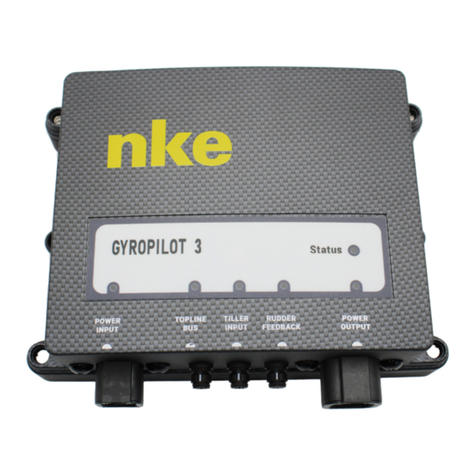
•Control the nke Gyropilot2 or Pilote HR
•Display data from the sensors connected to the Topline bus in digital, analog
or graphic format and access to setup parameters and alarms.
•Interface to NMEA 183 devices to provide relevant data to the Topline bus.
2 USE
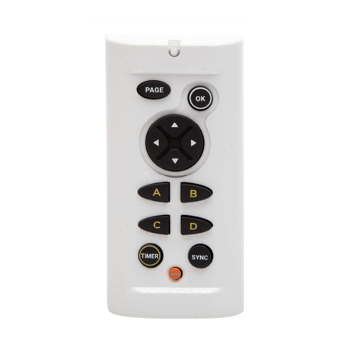
The Multidisplay doesn’t have an integrated keyboard, therefore it is necessary to
use a Pad (display or pilot) or a transmitter (display or pilot) in order to control the
display.
See Pad (display or pilot) or transmitter (display or pilot) manuals.
•PAGE
Successive presses will scroll through the pre-set data pages, the pilot page
and the setting page.
Press and hold (at least 3 seconds) to open the Menu page.
•OK
A single press confirms the current selection, or opens specific setup features
on some pages.
Press and hold (at least 3 seconds) to open the settings page for
backlighting, keyboard lock and stand-by mode.
•Cursor pad
Use for the selection of pages and menu options.
•. A,B,C,D (Pad display)
Those keys are shortcuts allowing access to different pages already programmed.

Page 5/55 68_Afficheur_Multidisplay_um_UK_11
•-1, +1, -10, +10 (Pad Pilot)
Use to control the autopilot’s course in 1° or 10° increments to Port or
Starboard.
Press and hold the 10° to tack.
•AUTO
Single press to engage the autopilot.
Press and hold this key to go directly to the Pilot Mode menu.
•STOP
Single press to disengage the autopilot.
•Mob
Press and hold to activate the man Over Board function on the Topline bus.
2.1 MENU PAGE
Parameters
s
Sensor
Alarm
P
erformance
Pilot

Page 6/55 68_Afficheur_Multidisplay_um_UK_11
When the Multidisplay is used for the first time it displays a screen with a menu
providing access to:
•the sensor settings
•the alarm settings
•the pilot settings
•the Performance page setup
•the parameter settings
Press the cursor pad’s arrows « left » and « right » to scroll through the menu icons
for selection.
2.2 PAGE BUILDING WIZARD
The Multidisplay has been designed to enable the user to customise pages. 10
pages can be set up according to the user’s preference with the first 8 pre-set to
default settings.
To build a page, first select the « Parameters » icon in the menu.
•Select pages and press .
•Select the page you want to build or edit with the up and down arrows .
Empty pages are grayed out. Once you have made your selection, confirm
with .
11 pages are available; the first one is for the pilot and the other are
numbered from 0 to 9.
2.2.1 Page format
You can choose between different layouts for the page. Press , a list will appear.
Select the screen layout template with the « up » and « down » arrows on the pad.
, depending on the format you wish to display on the page.

Page 7/55 68_Afficheur_Multidisplay_um_UK_11
Screen types available in landscape orientation :
1 line Displays 1 data
2 lines Displays 2 data
4 lines Displays 4 data
6 lines Displays 6 data
1+3 lines Displays one main data on the left and
superimposes 3 thumbnail data to the
right
4/4 page Displays 4 data on the same page and
alternates every 3 seconds with 4 other
data
1/1 page Displays 1 data and alternates with 1
other data every 3 seconds
XTE page Displays the waypoint difference at
Waypoint
Waypoint page Displays the Waypoint heading from the
COG
Screen types available in portrait orientation :
1 line Displays 1 data
2 lines Displays 2 data
3 lines Displays 3 data
4 lines Displays 4 data
Once you have made a choice, press to confirm.
4/4 et 1/1
This page is used to display 4 information that alternate with 4 other
information. It can also be used with feedback from racing software
(ADRENA, EXPEDITION,…) via the NMEA input after initialization (see
"NMEA initialization"). For example, the ADRENA software can be used to
feedback 8 information according to the phases of race, those information
can be read on these alternative pages. This information can be read on all
Multidisplay of the Topline network. The 8 channels available are named DYN1 to
DYN8.

Page 8/55 68_Afficheur_Multidisplay_um_UK_11
2.2.2 Edit a page
This setting selects the data that will be displayed on the selected page
FOLLOWING to accept the current data in that selected part of the screen (only for
multiple line pages) and go to the next page partition.
MODIFY to change the information and the colour in which it will be displayed by
selecting from a list.
Groupe
Data
Wind
Apparent wind angle
Apparent Wind Speed
True Wind angle
True Wind Speed
Magnetic True Wind Direction
Navigation
Depth
Boat Speed
Ultrasonic Speed Sensor
Magnetic heading
True Heading
Corrected Heading
Trip Log
Total Log
Maximum Speed
Average Speed
DR1 distance
Reckoned bearing
Pilot
Pilot consumption
Pilot Voltage
Rudder Angle Sensor
Energy
Bus Voltage
BAT1 Voltage
BAT1 Current
BAT1 Capacity
BAT1 Level

Page 9/55 68_Afficheur_Multidisplay_um_UK_11
BAT1 Energy
BAT2 Voltage
Performance
Timer
CMG
Optimum Wind Angle
Drift Angle
Direction of measured current
Speed of measured current
GPS
Speed over ground
Heading over the ground
Magnetic COG
Distance to Waypoint
Bearing to Waypoint
Cross-Track Error
Position
Time
Date
Declination
Weather
Air Pressure
Sea temperature
Air temperature
Specific sensors
Heel
Pitch
Forestay tension
Mast Angle Sensor
HR Mast Angle Sensor
Engine hours
All
…….
FINISH to confirm the page and save the settings.
Note:
Some partitions of the page can display the information in analogue, graphic or digital
format.

Page 10/55 68_Afficheur_Multidisplay_um_UK_11
Once the page has been built a window opens allowing you to save and rename the
page.
Press to save the page.
Select Name with the pad and press button to access the virtual keyboard.
Use the pad keys to select letters and press to confirm your choice. Repeat
the action for each entry.
Toggle between numbers and letters.
Caps lock.
Delete last digit
Enter, to confirm the name and save the page.
2.2.3 Visible
The six first pages are visible by default.
Press to hide the page.
Unhidden “ON”
Hidden “OFF”
2.2.4 Edit name
Edit the page name with the virtual keyboard.
2.3 DISPLAY PAGES
Scroll through the build pages, the pilot and menu pages by pressing the
button with successive presses.

Page 11/55 68_Afficheur_Multidisplay_um_UK_11
2.4 USE OF THE MULTIDISPLAY AS MULTIFUNCTION DISPLAY
Multidisplay is a multifunction display from the TOPLINE range of products. It
connects to the TOPLINE bus on your system and displays all data available on the
bus.
The keyboard, curser pad and scroll down menus make all aspects of the system
easy to use. Multidisplay facilitates control and use of your Topline system.
2.4.1 Edit an existing page
Once a page has been built (see paragraph 2.2), it can be edited to show temporary
or permanent changes.
2.4.2 Temporary modification
Temporary modification of a page allows data of your choice to be displayed without
saving a new layout.
•Browse through the page with .
•Highlight the data to modify and press .
•With choose the replacing data and press .
This modification has not been saved and the previous layout will return the next time
the system is powered on.
2.4.3 Permanant modification of a page constructed
Permanent modification allows modifying the page constructed and saving new
elements.
This is carried out in « parameters ». In order to modify a page, see chapter 2.2 page
building wizard.
2.5 SETTING PARAMETERS
Press and hold to display the main menu in which you select for the
«Parameters» page.
Use the up and down arrows of the pad to select and to confirm.

Page 12/55 68_Afficheur_Multidisplay_um_UK_11
2.5.1 Display Settings
The Display Settings menu gives access to:
•The Display Mode
•The Daylight Mode settings
•The Night Mode settings
•The Stand-by timing
2.5.2 Backlighting
The backlighting can toggle automatically between Night and Day settings, driven by
a light sensor, or can be manually set. Backlight settings can be adjusted as required
for each Multigraphic independently.
Backlight setup process:
•Select «Display setting » and press .
•Highlight « Display mode » and press .
•Choose « Auto » or « day » or « Night » and press .
Auto: Backlighting toggles automatically between Night and Day settings, driven by a
light sensor. The Backlight intensity and the Skin are those set for each Mode.
Day: Backlighting is on with the light intensity and the Skin set for Day Mode.
Night: Backlighting is on with the light intensity and the Skin set for Night Mode.
There are 20 levels of Backlighting.
Whatever page is currently displayed press and hold « OK » for 3 seconds
to access directly to the backlight levels settings.
2.5.3 Setting Night and Day modes
Setting procedures are identical for Day mode and Night mode.
Backlight intensity setting: 1 to 20
•Go to «Display setting» and press .
•Choose « Day adjustment » or « Night adjustment » and press .

Page 13/55 68_Afficheur_Multidisplay_um_UK_11
•Press again and modify the value « light level » with . Then press
to save the parameter.
2.5.4 Skin Settings
•In « parameters » choose « Display Setting » and press .
•Choose « Day adjustment » or « Night adjustment » and press .
•Select « Skins » and press
•Select the skin desired with the key and press to save the parameter.
You can choose between 5 Skins for Day and Night modes. The default Skins are
white for Day and black/red for night.
Some skins are more appropriate than others, depending on the reading angle.
2.5.5 Display’s Standby timing
A time can be set up to 30 minutes. When the selected time is reached the display
will be put in a “sleep mode” for power saving. The Multigraphic will keep working
and the screen can be resumed with the simple press of any key or selecting the
display on a remote control.
Setting the Display’s Standby timing:
•In « parameters » select « Display setting » and press .

Page 14/55 68_Afficheur_Multidisplay_um_UK_11
•Choose « Standby time » and press .
•Modify the value with and save with .
Press and hold the “OK” key for 3 seconds to enter the Display Standby
setting menu. This can be done from any page.
2.5.6 Data logging : « stripcharts » settings
4 different sets of data can be logged simultaneously over a 48 hour period with a 15
seconds log rate. The logged data can be displayed on stripcharts on the
“Multidisplay”.
“stripcharts” settings process:
•In « parameters » select « Logger configuration » and press .
•Choose the logger to modify among the 4 available and press .
•With , modify the data and save with .
2.5.7 A,B,C,D keys configuration of the multifunction Pad
Keys A, B, C and D enable to display the pages programmed on all the displays.
In >> Parameters >> shortcuts configuration: select one of the keys to program and
press Choose in the list the page desired. By default no key is programmed.
2.5.8 Language selection
Your Multigraphic can be set to display menus in various languages.
Language setting process:
In « parameters » choose the language and press to save your choice.
2.5.9 Unit selection
The Multidisplay can be set to use various units for boat speed, depth, air
temperature, sea temperature and wind speed.

Page 15/55 68_Afficheur_Multidisplay_um_UK_11
Depending on the information selectable units are “knots”, “meters per second”,
kilometres per hour”, “degrees Celsius” and “degrees Fahrenheit”.
•In parameters go to « Unit Selection » Select the unit and press
•Choose the unit and press to save.
2.5.10 Maintenance
2.5.10.1 Multidisplay node address in the Topline system
In this menu you have to give a Topline address to the Multidisplay. With address
n°1 it will be considered as « Master » and manages the whole system. If there is
already a Master », the Multidisplay will get an address different from 1 and it will
behave as « Slave ». This process is carried out automatically: if there is no
« Master » in the system, the Multidisplay will automatically be selected as
« Master ». Systems with an existing « Master » will automatically deliver a « Slave »
address to the Multidisplay.
Note: the Multidisplay comes with a factory default setting as n°0. It has no address
and it cannot work with your system. Giving an address to the Multidisplay is the
very first setting to do once the display is connected to the Topline bus and the
installation complete.
Multidisplay address process:
•Connect the red wire of the Multidisplay on the braid and start the installation.
•A message appears on the display : « disconnect the red wire to start
initialization » (follow this procedure)
•The Multidisplay starts automatically and takes the first Topline address
available. After this procedure, please isolate the red wire in your nke bus
junction box.
•Resetting the address to 0 :
•With the Pad display, go to >> >> Maintenance >> Topline address.
Select « Erase » and save with .
Address change process :
•With the Pad display, go to >> >> Maintenance >> Topline Address.
Select « Yes » and save with .
•The Multidisplay takes another address and takes the first one available.

Page 16/55 68_Afficheur_Multidisplay_um_UK_11
Once this procedure is complete, the Pad won’t have any control on the
Multidisplay, you’ll have to execute the address taking process to be able to
control the display. In case of “master bus lost” it is possible to reconnect the
red wire to reset the address to zero and start the address taking process.
2.5.10.2 Auxiliary inputs
2.5.10.2.1 Console
The Multidisplay has a NMEA console allowing NMEA input data to be displayed.
2.5.10.2.2 NMEA settings
The Multidisplay features a NMEA0183 input which allows any compatible
instrument (GPC, PC…) to be connected. This port converts any NMEA incoming
data to Topline channels if they do not already exist on the Topline bus. The data
will be used by the Topline system. Baud rate is automatically detected between
4800 or 38400 Bauds.
NMEA input settings:
•In >> parameters >> maintenance >> external devices >> NMEA init, Select
« NMEA init », then press , to initialize press again.
•A window opens and asks: « Do you want to start a capture? »
•Press . Wait during the capture. Once complete, a certain amount of
channels will be available.
•Press « Validate », channels available will be listed.
•On the Topline network it is possible to display or not, the channels available
in NMEA. All NMEA channels are activated by default. You can choose to
inhibit some channels. This is done by selecting the chosen channel and
pressing .
•Pressing ends the NMEA initialisation by updating all channels available on
the Topline bus.
2.5.10.3 Topline Instrument system
This system menu displays the properties and software versions of all the sensors
and displays connected to the Topline bus.
2.5.10.3.1 GPS statistics
If a GPS is connected in NMEA it is possible to see the statistics of this GPS

Page 17/55 68_Afficheur_Multidisplay_um_UK_11
2.5.10.4 Orientation
It is possible to change the layout of your Multidisplay. To do so, go in >>
parameters >> maintenance >> orientation: select « landscape » or « Portrait »
and save with .
2.5.10.5 Keypad Beep
The keypad beep is a sound emitted by the Multidisplay when a command is
sent by the Pad display or Pad pilot. It is possible to activate or inhibit this sound in
>> parameters >> maintenance >> Keypad Beep.
2.5.10.6 Firmware
This page displays the Multidisplay software version and date of issue.
Display the firmware:
•In parameters >> maintenance >> Software: press to see the Firmware
and bootloader version.
•Press to quit.
2.5.10.7 Memory
This menu allows the user to reset the Multidisplay to factory settings.
Reset the Multigraphic :
•Select « Memory » and access to the options by pressing .
•Select « Yes » to erase the memory by pressing
2.5.10.8 Simulator
There is a simulator available in the Multidisplay. Once activated, it sends random
data to the Topline bus.
Simulator menu:
Select « Simulator » and choose « on » or « off », save your choice with .
By default, the Multidisplay is in landscape with the logo nke on the right. In
portrait, the logo is at the bottom of the screen.
Some parameters are not available in Portrait such as the type of page.
WARNINGS:

Page 18/55 68_Afficheur_Multidisplay_um_UK_11
2.5.10.9 Autotest
Autotest is useful to check the Multidisplay. This procedure verifies the following
functions step by step:
•keys
•colour display
•light sensor (vlight), internal temperature sensor, power supply.
•backlighting
•memory
•Topline bus
•NMEA input and output (connect the yellow and red wires together for that
operation).
•Data logged in cookies
Proceed to each step by confirming with .
•Select « Autotest » and choose the option with .
Follow the instructions and press to go to the next page.
If your display is in portrait orientation, the autotest process is not available.
WARNING
:

Page 19/55 68_Afficheur_Multidisplay_um_UK_11
2.6 SENSOR SETTINGS
Go to the main menu by pressing and select to display the
« sensors » page.
All sensors connected to the Topline bus can be calibrated from this menu. Settings
are different for each sensor. Refer to the sensor’s manual for more information.
Main settings:
•Filter : the filter takes the data average value to set a data refresh rate. This
damping set for apparent wind speed, boat speed and heading (Regatta
compass) affects the autopilot’s “True Wind” mode.
•Offset : applies a correction to data for some sensors.
•Coefficient : applies a correction factor for calibration.
•Reset : back to default settings of the selected sensor.
Data set up process:
•Select the data you want to modify and press .
(Trip Log, Apparent Wind Angle, Boat speed…)
•Modify it with and confirm with .
2.6.1 Calibration wizard
Calibration wizards are available to help you calibrate the apparent wind angle, the
boat speed and a fluxgate compass (not available for the REGATTA compass).
2.6.2 Apparent Wind Angle calibration wizard
Sail 4 legs upwind to measure the average wind angle on each
tack. A wind vane offset will be calculated and applied to correct
the Apparent Wind Angle.
Apparent Wind Angle values must be similar from one tack to
another (+-1°) when the calibration is correct. If this is not the
case, the wind may have shifted, or the crew cannot sail with the
same angle on each tack upwind!

Page 20/55 68_Afficheur_Multidisplay_um_UK_11
Calibration of the Apparent Wind Angle:
•Select « Apparent Wind Angle » and press .
•Choose « Calibration Wizard » and press .
•Select « Start » and press .
•Go on Starboard Tack and press . Wait and press .
•Go on the Port Tack and press . Wait and press .
•Repeat this procedure one more time.
•A window will open with the new Offset and ask to save the new one or keep
the old one. To save the new one select « yes » and confirm with .
2.6.3 Speed through water calibration wizard
The boat speed is calibrated with the speed over ground as reference. You have to
sail 0.5 nM on a constant heading and then sail back (180°) the same distance. The
new calibration is processed from the current calibration value already saved (there
is no need to reset the calibration value to 1).
The COG (Course Over Ground) function must be displayed on the Topline network
to achieve the boat speed calibration.
Boat speed calibration:
•Select « Boat speed » and press .
•Choose « Calibration Wizard » and press .
•Select « Start » and press .
•When your heading and speed are approximately steady, press .
•Go about 0.5 Nm in those conditions and press .
•Make a U turn (Your current heading + 180°) and press .
•Hold your course at a constant speed during 0.5Nm. Once complete press
•A window will open and ask you to save the new factor. If satisfied, select “yes”
and save with .
Table of contents
Other NKE Marine Equipment manuals

