NKE HR Masthead unit Instruction Manual
Zi de Kerandré – Rue Gutemberg – 56700 – HENNEBONT – FRANCE
www.nke-marine-electronics.com
HR Masthead unit
Product reference : 90-60-369
USER GUIDE
and
INSTALLATION GUIDE

-
2
-
38_Anemo-Girouette_HR_um_UK_28
TABLE OF CONTENTS
1
USING ..................................................................................................................................................................................3
1.1
P
RESENTATION
..............................................................................................................................................................3
1.2
L
IST OF CHANNELS DISPLAYED
......................................................................................................................................4
1.3
A
LARMS SETTING
..........................................................................................................................................................4
1.4
F
ILTERING OF THE CHANNELS
........................................................................................................................................4
1.5
C
HOICE OF THE UNIT
......................................................................................................................................................5
1.6
T
ECHNICAL SPECIFICATIONS
..........................................................................................................................................5
1.7
D
IAGNOSTIC OF
1
ST
LEVEL TROUBLESHOOTING
..............................................................................................................5
2
CALIBRATION ..................................................................................................................................................................6
2.1
C
ALIBRATION OF THE WIND VANE
.................................................................................................................................6
2.2
C
ALIBRATION OF THE ANEMOMETER
.............................................................................................................................7
3
INSTALLATION ................................................................................................................................................................8
3.1
L
IST OF ACCESSORIES
....................................................................................................................................................8
3.2
INSTALLATION PRECAUTIONS
........................................................................................................................................8
3.3
INSTALLATION OF THE
M
OUNTING PLATE AND OF THE VANE SUPPORT
..........................................................................9
3.4
W
INDMILL MONTING PROCEDURE
..................................................................................................................................9
3.5
CONNECTION TO THE TOPLINE BUS
.................................................................................................................................9
4
MAINTENANCE ..............................................................................................................................................................10
-
3
-
38_Anemo-Girouette_HR_um_UK_28
1 USING
1.1 PRESENTATION
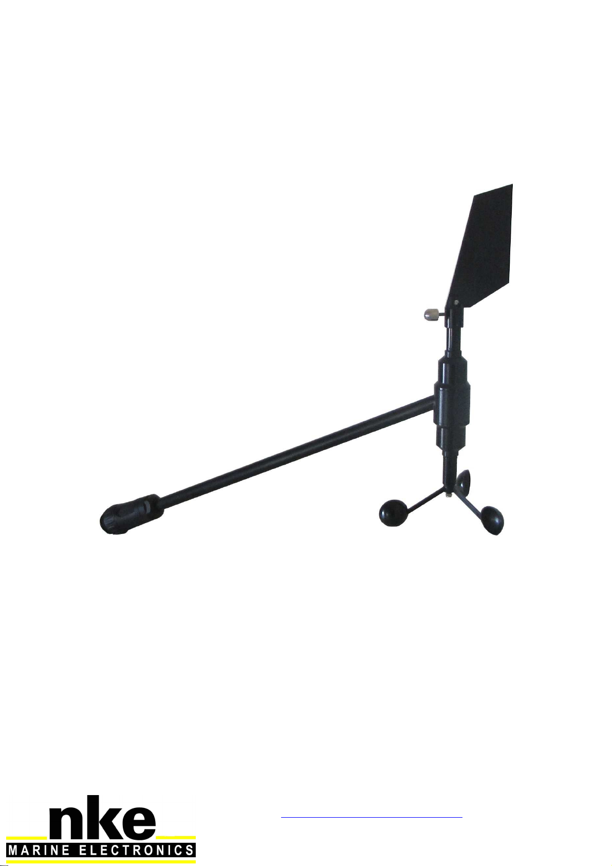
The HR masthead unit is a measuring instrument for wind speed and direction. It is connected
to the TOPLINE bus of your installation. Equipped with high quality ball bearings and
mechanical elements of precision, the HR masthead unit guaranteed qualities of a reliable,
precise and sensitive sensor.
The support equipped with a TOPLINE bus cable, is not provided with the masthead unit.
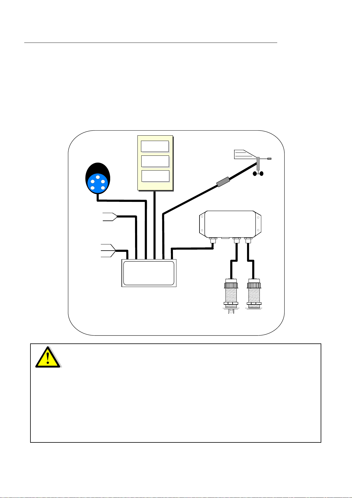
ARCHITECTURE OF THE INSTALLATION
IMPORTANT
-Do not dismantle masthead unit parts
-Read this user guide entirely before starting the installation.
-The electrical connection of the TL25 on the TOPLINE bus must be carried out with
the terminal box 90-60-121. Only use TOPLINE bus cable of the type 20-61-001.
-Any intervention on the TOPLINE bus must be carried out with the installation power
switched off.
Cable TOPLINE
20-61-001
GND
DATA black
12VDC white
Figure 1
log depth interface
90-60-450
log
speedomètre depth
connecting box
90-60-417
NMEA -
NMEA +
input NMEA
nke
TL 25
16.85
BOAT SPEED
APP WIND A
105-
KNOTS
DEGRES
10.50
DEPTH
METERS

-
4
-
38_Anemo-Girouette_HR_um_UK_28
1.2 LIST OF CHANNELS DISPLAYED
The masthead unit, connected to the TOPLINE bus of your installation, creates the channels
below. They are then accessible using the displays of the TOPLINE range.
Channel Display Unit
Apparent wind speed WIND SPD / A
0.0Kt m/s or knot
Apparent wind angle WIND ANG / A
0
° degree
Air temperature
Air temp
15.4
° °C or °F
If your installation is equipped with a speedometer
True wind speed WIND SPD / T
0.0
Kt m/s or knot
True wind angle WIND ANG / T
45
° degree
If your installation is equipped with a TOPLINE compass
True wind direction WIND DIR / T
300
° degree
The apparent wind angle is displayed in degrees : from 0° to -180° on port tack and from 0° to
180° on starboard tack.
1.3 ALARMS SETTING
The setting of an alarm enables you to monitor the value of a channel. When the preset
threshold is exceeded, a warning message is displayed and an audible alarm is activated.
The upper alarm is activated when the display is higher than the programmed threshold.
The lower alarm is activated when the display is lower than the programmed threshold.
To cancel the alarm of a channel, enter the value 0in the upper alarm and the lower alarm.
Thus, the setting of an alarm on the wind speed, wind angle or air temperature channels will
allow you to supervise your installation effectively as well as the good operation of your boat.
To activate alarms, please refer to the user guide of your display.
1.4 FILTERING OF THE CHANNELS
The level of filtering of a channel determines the frequency of update of the data displayed.
For example, in rough sea when the boat moves significantly, it is useful to increase the filtering
of the speed channel to stabilise the value displayed. Conversely, in calm sea, low filtering will
be preferable to obtain a fast response of the display.
Filtering is adjustable between 1and 32, and the default value is 8. The lower this value is, the
higher the frequency of update is.
Please refer to the user guide of your display to carry out the filter setting.

-
5
-
38_Anemo-Girouette_HR_um_UK_28
1.5 CHOICE OF THE UNIT
You have the option to choose the following display units :
-Wind speed : in knots or in m/s.
-Air temperature : in degree Fahrenheit or in degree Celsius
Please refer to the user guide of your display to carry out this change of units.
1.6 TECHNICAL SPECIFICATIONS
-Power supply : 10 to 16VDC
-Consumption : 25mA
-Wind speed range : tested in laboratory, 0 up to 60 knots.
-Wind speed sensibility: < 2 knots.
-Angular resolution of the anemo wane : 1°
-Air temperature range : -10°C à +50°C
-Tightness :IP67
-Weight : masthead unit : 180g – Mounting plate and support : 160g
-Bus cable : Ø 5.0 ±0.3 – weight : 34 g/m.
-Operating temperature : -10°C to +50°C
-Storage temperature : -20°C to +60°C
1.7 DIAGNOSTIC OF 1
ST
LEVEL TROUBLESHOOTING.
Before contacting technical support, please check the troubleshooting table below.
Problem
Possible causes and solutions
The Topline installation does not detect the masthead unit.
The bus cable is not or is badly connected to the terminal box : check the
connection inside the terminal box. Check the state of the cables : they
must not show any sign of wear or cut.
The apparent wind speed indicates
0.0, no matter what
the
wind speed is. Check that the calibration coefficient is different from
0.0
: refer to §3.
Check that the winch is not blocked.
The apparent wind speed indicates
0.0
and the air temperature
channel indicates « Pan ». It is possible that the masthead unit is disconnected or broken. Check the
state of the cable and the connection to the box.
The apparent wind angle indicates 35° at close haul on one
board and 65° on the other. Check that the stem of the masthead unit follows the axis of the boat
Carry out a calibration of the vane: refer to §3.
If you do not manage to solve the problem, please contact your distributor.

-
6
-
38_Anemo-Girouette_HR_um_UK_28
2 CALIBRATION
The masthead unit is adjusted at the factory. However, a calibration is required to adapt the
sensor to the specificities of your boat and to obtain an optimum measurement accuracy. Follow
the calibration procedure below, by visualising the settings on a display: please refer to the user
guide of the display.
2.1 CALIBRATION OF THE WIND VANE
2.1.1 Principle of the calibration
After the masthead unit has been installed, a real test at sea needs to be carried out. You will
sail on port tack and on starboard tack in order to raise the wind angle displayed on the channel
APP WIND ANGLE. Then, you will deduce the offset value which will enable you to adjust the
wind vane. Thus, a calibration rectifies all the shifts that result from an installation at the head of
mast : assembly position (alignment), torsion and inflection of the mast during navigation.
Note that each wind vane is set with a factory offset. This offset ranges between 0° and -180° or
between 0° and +180°. It is the reference of your wind vane in relation to the axis of the support
stem. Before the start of a calibration, we recommend that you make a note of this value as it
may be useful in case of bad handling.
2.1.2 OFFSET setting procedure
To achieve a successful calibration, sail on a calm sea, with a moderate wind.
1. Display the channel APP WIND ANGLE.
2. Sail and follow several close-hauled tacks : note the values of apparent wind angle displayed.
3. Calculate the average of the values displayed on starboard tack and those displayed on port
tack.
4. Calculate the offset correction : ( average starboard angle -average port angle).
2
5. Adjust the factory offset with the value of offset calculated
Example 1
:
Factory OFFSET = 60
Average apparent wind angle starboard tack :45°
Average apparent wind angle port tack :35°
Value to be added to the factory OFFSET = (45°-
35°) / 2 = 5 °
New offset value = 5 +60 = 65
Example 2
:
Factory OFFSET = 60
Average apparent wind angle starboard tack :39°
Average apparent wind angle port tack :45°
Value to be deducted from the factory OFFSET =
(39°- 45°) / 2 = - 3 °
New offset value = 60-3= 57

-
7
-
38_Anemo-Girouette_HR_um_UK_28
2.2 CALIBRATION OF THE ANEMOMETER
2.2.1 Principle of the calibration
You will adjust the calibration coefficient of the channel apparent wind speed, so that the
speed displayed is equal to the true ambient wind speed.
You can carry out this calibration at port.
2.2.2 Setting procedure of the calibration coefficient
1. Select the calib coef sub-channel of the apparent wind speed channel.
2. Enter the new calibration coefficient and validate using the enter key. The new setting will
be saved to the memory.
-
CAUTION
:
The
calib coef
parameter is a multiplier coefficient. This value must never
be equal to zero. By default this coefficient is set to 1.00. If it is not the case, before
starting a calibration enter the value 1.00.

-
8
-
38_Anemo-Girouette_HR_um_UK_28
3 INSTALLATION
The masthead unit is attached to the mast using a plate support. Two versions are available:
−90-60-509 plate equipped with 25 meters of cable.
−90-60-562 plate equipped with 35 meters of cable.
Measure the length of cable necessary to connect the sensor, attached at the head of mast, to
the TOPLINE bus terminal box inside your boat. Choose the appropriate plate.
3.1 LIST OF ACCESSORIES
-25 meter masthead unit cable, with plate and support : 90-60-509
-35 meter masthead unit cable, with plate and support : 90-60-562
-TOPLINE terminal box : 90-60-121
-Windmill : 90-60-503
-Vane : 31-02-050
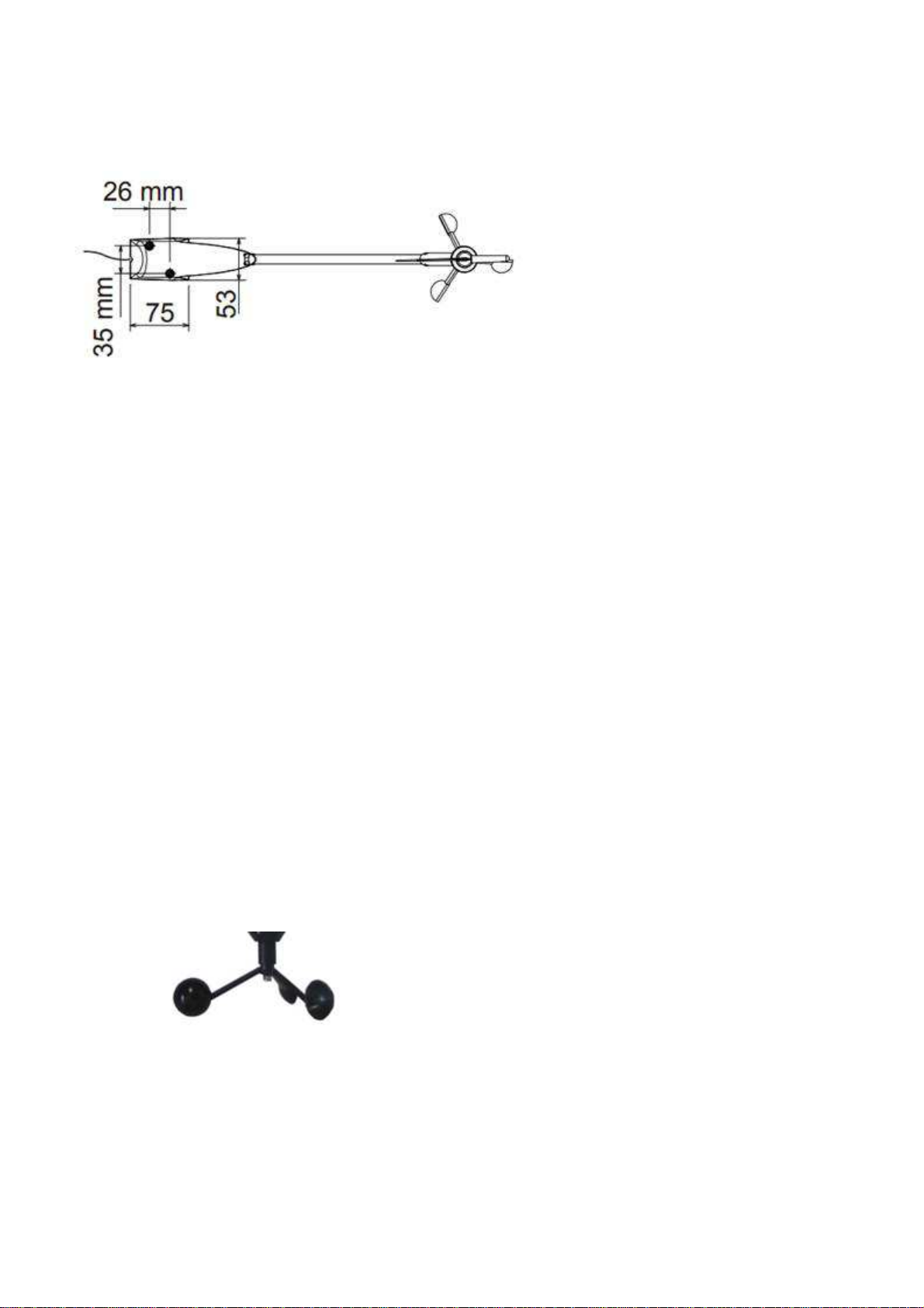
3.2 INSTALLATION PRECAUTIONS
The choice for the location of the masthead unit is crucial to achieve optimal performances.
The location of the sensor must be:
-as high and distant as possible from any equipment blocking or disturbing the air flow.
-
horizontal. If the mounting surface is not horizontal, for example the mast head is at an
angle, manufacture a taper gib (figure 2).
-
-
9
-
38_Anemo-Girouette_HR_um_UK_28
3.3 INSTALLATION OF THE MOUNTING PLATE AND OF THE VANE SUPPORT
The attachment system of the wind vane comprises a vane support. You will start by attaching
the support at the head of the mast, then you will mount the wind vane onto the support.
The support is assembled using two screws. The support must be installed on a horizontal,
clean, smooth and flat plane. You will attach the support using tow M5X35mm screws (not
provided) so that the stem of the wind vane is in line with the axis of the boat. The sensor will
then be screwed to its socket and blocked by a nylon collar (supplied).
Mounting procedure
1. On the horizontal plane of the mast head, drill or tap tow Ø5mm holes for the attachment of
the support.
2. Coat the interior face of the plate with sealing putty
3. Attach the support using tow screws M5X35mm (not provided).
4. Run the cable inside the mast, preferably in a sleeve. The entry and exit of the mast must be
protected using a grommet.
5. Remove the protective cap of the connector.
6. Introduce the wind vane into the socket of the support and screw the vane connector
manually. Put on the nylon collar.
3.4 WINDMILL MONTING PROCEDURE
1. Make correspond the flat surface of the windmill with the flat surface of the axis.
2. Insert the windmill on the axis
3. Insert and tight the nut.
3.5 CONNECTION TO THE TOPLINE BUS
If the cable runs inside the mast, make the cable pass through an opening equipped with a
grommet. If the cable runs across the deck, make the cable pass through a tight stern tube
gland.
1. Make the masthead unit cable run towards the TOPLINE terminal box of your installation.
2. Connect the bus cable inside the terminal box :

-
10
-
38_Anemo-Girouette_HR_um_UK_28
If you cut the bus cable, you will need to galvanise the wires after stripping them.
4 MAINTENANCE
The axes of the wind vane and of the anemometer are mounted on ball bearings and rotate
permanently. If the opportunity presents itself, we advise you to dismount the masthead unit
from its support, during wintering periods, in order to increase the lifespan of the bearings.
If you set down the wind vane, because of dismasting or wintering for example, screw the
stopper onto the connector of the wind vane support.
BLANC
NU
NOIR
BLANC
NU
NOIR
12V
gnd
Supply 12Vdc
+
connecting box
90-60-121
Ent Esc
VITES
SURF
1.20
Nd
-
GND
DATA black
12VDC White
Figure 4 : connection to the TOPLINE bus
This manual suits for next models
1
Table of contents
Other NKE Marine Equipment manuals


