VMB TL-A220 User manual
PROLIFTSS.L. V.11.03 - Depósito legal y Copyright 2011. Todos los derechos reservados.
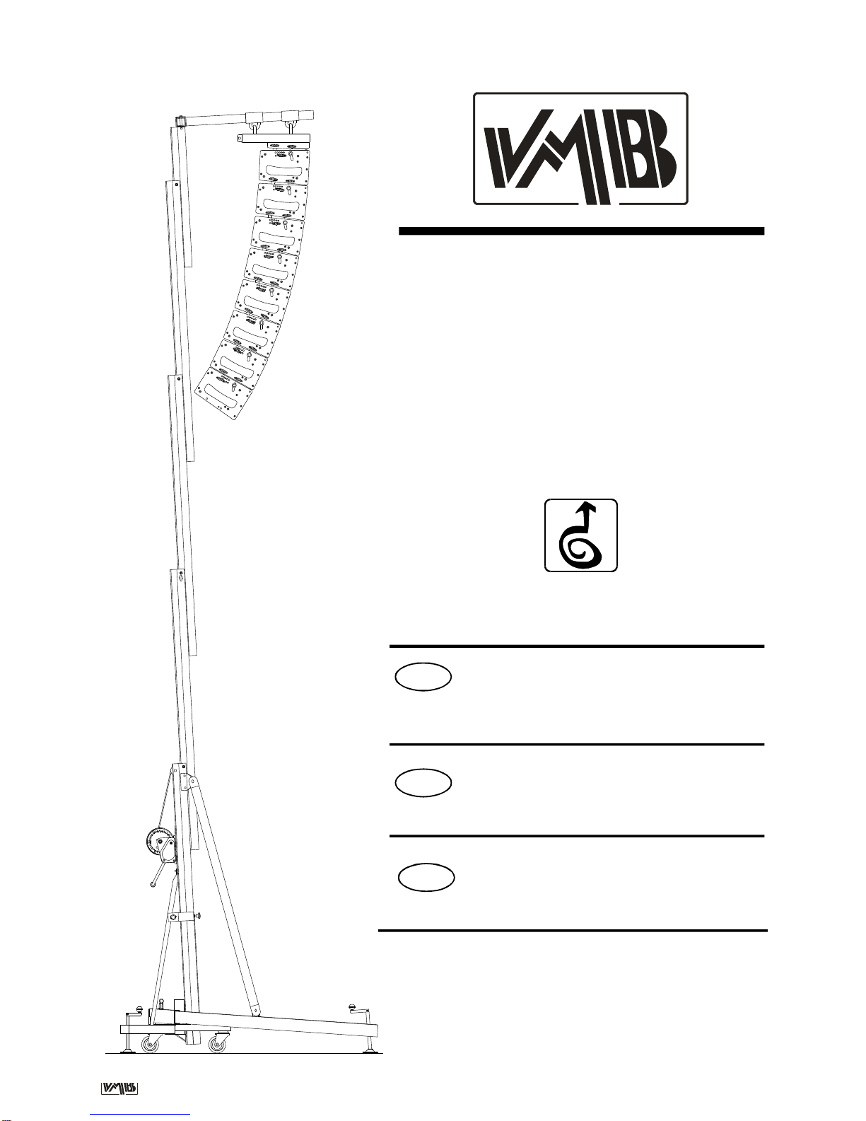
TL - A220
EELEVADOR LINEARRAY
MANUAL DE INSTRUCCIONES
LINE ARRAY LIFT
INSTRUCTION MANUAL
Quick Operation Guide
GB
DTRAVERSENLIFT
BEDIENUNGSANLEITUNG
Fabricante - Manufacturer - Hersteller - Fabricant
TORRE ELEVADORA
TOWERLIFT
TRAVERSENLIFT
PIED ÉLÉVATEUR TL-A220
PRO LIFTS S.L.
Calle 7 final - Pol. Ind. Picassent
E-46220 Picassent (VALENCIA) SPAIN
www.prolifts.es - info@prolifts.es
Este manual de usuario y catálogo anexo de piezas de repuesto es propiedad de PRO LIFTS S.L.
Queda prohibida su reproduccion total o parcial por cualquier medio que la tecnología actual permita.
Depósito legal y Copyright 2008. Todos los derechos reservados.
PROLIFTSS.L. V.11.03 - Depósito legal y Copyright 2011. Todos los derechos reservados.
TL-A220
X
P1
BU ALS
ALS
P1BU
V
BR
BA
H
QT
P
JJ
S
C
ILS
DH
W
F
E

PROLIFTSS.L. V.11.03 - Depósito legal y Copyright 2011. Todos los derechos reservados.
CONTENTS
1. Introduction.
2. Technical Data.
3. Security.
4. Instructions.
5. Maintenance.
6. Warranty.
7. Certifications.
1. INTRODUCTION
Thank you for choosing VMB Towerlifts.
You haveacquired afirst class,quality product
used by professionals around the world.
To be able to work with this tower, lifting and
flying PA and Line Array, please pay special
attention to this manual. Please observe the
technical data and follow all instructions fully
for a correct and safe use.
Thismanualshouldalsobemadeavailableand
remain with the towerlift.
All VMBtowerlifts undergo a strict quality con-
troltoguaranteemaximumsafetyanddurability.
The TL-A220, has been especially designed
and engineered to hang Line Array to a
maximumheight of 5,5manda loadof 220kg.
ThisliftiscapableofsituatingthePA50cmfrom
thebodyofthelift.
The benefit of placing the load at a distance
enables the user to achieve the perfect curve
and coverage for the Line array flown.
The TL-A220, incorporates the ALS system
(Auto-Lock-Security) and ILS system(Inertia-
Lock-Security)all exclusive to VMBand which
guaranteetheloadwillnotfallandprovidecom-
pletesecurity.
ATTENTION: Do not use this towerlift if you
havenot readand understoodtheinstructions.
2. TECHNICAL IINFORMATION
2.1- Towerliftmod. TL-A220
2.2 - Especially designed for lifting and flying
Line array directly fromthe floor to a height of
5.5m(18’).Abletohangat50cm(1.6’)fromthe
mainbodyofthe lift.
2.3 - Maximum load : 220Kg (485lb). at 50cm
(1.6’) fromliftbody..
2.4 - Minimum Load : Can lift or lower without
load.
2.5 - Maximum Height: 5,5 m(18’).
2.6 - Folded Height : 1,72 m(5.6’).
2.7 - Base Surface : 2.1 x1.6m (6.9 x5.2’).
2.8 - TransportWeight :95Kg (209lb).
2.9-ConstructionMaterial:6082-T6aluminium
for the main body comprised of 4 profiles and
liftingcarriage.DIN2394steelfor thebaseand
outriggers. ST-37 steel for the ALS security
systemandpulleys.
2.10 - Security Systems: ALS (Auto-Lock-
Security), ILS (Inertia-Lock-Security) which
guaranteecompletesecurityat all times.
Duringthelifeofthistowerlift,itmayneedspare
parts for maintenance. In this case please
contactyour distributor.
Only original spare parts must be used. The
user loses all rights to warranty if any spare
partsotherthanoriginalsareused orcarrysout
anymodificationoralterationtothetowerlift.
For any questions relating to this towerlift
please indicate serial number and year of
production.
Quick Operation Guide ENGLISH
PROLIFTSS.L. V.11.03 - Depósito legal y Copyright 2011. Todos los derechos reservados.
Quick Operation Guide ENGLISH
2.11 - 900kgManualwinch withautomatic disc
brake.
2.12 - Cable : DIN 3060 steel. 180 Kg/mm2
qualityantitorsion.5mmdiametre.
2.13 - Adjustable stabilisers on the outriggers
withanti-slip injectedrubber base.
2.14 - Outriggersfixedwithsecuritylocks.
2.15 - Spirit levelto adjustvertical positioning.
2.16 -All lift elementsare finished in polyester
satin black.
2.17 -360ºWheelsforeaseoftransporttowork
place.
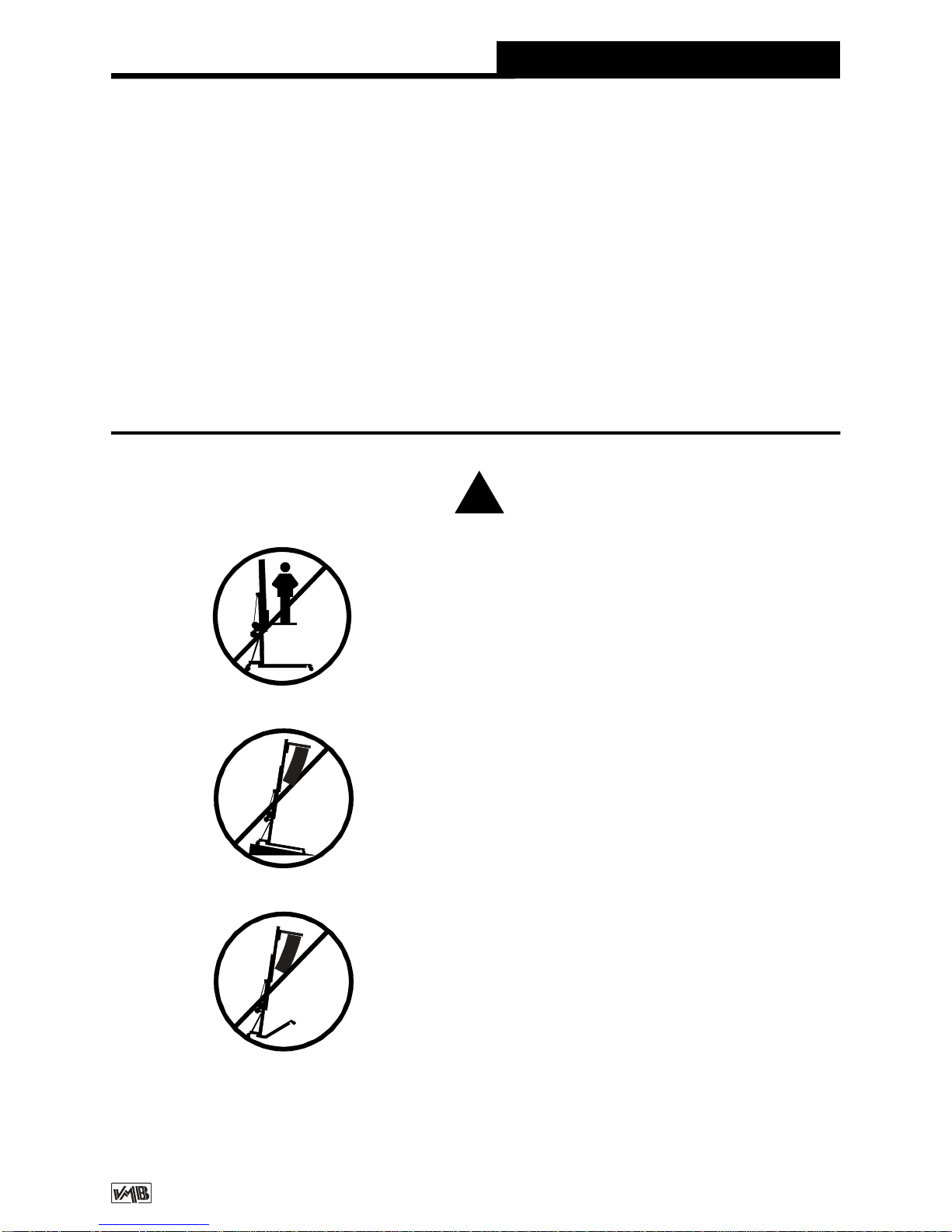
3. SAFETY PRECAUTIONS.
3.1-TheTL-A220isdesignedforlifingLine
Arrayandshouldneverbeusedforelevating
persons.
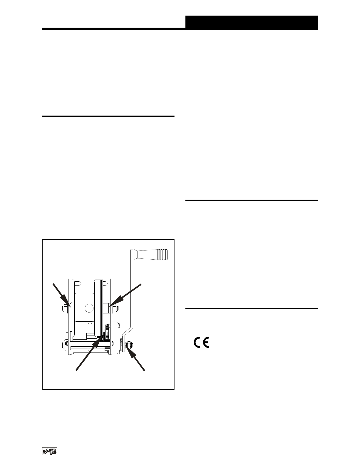
3.2 - Only situate the lift on hard, flat
surfaces checking that it is in a vertical
position withthe spirit level (F) included. If
necessary, adjust with support stabilisers
(Q) by turning the handle (H). Do not use
any other materials to balance the lift.
!
3.3 - Check all outriggers are inserted
correctly and locked with security locks.

PROLIFTSS.L. V.11.03 - Depósito legal y Copyright 2011. Todos los derechos reservados.
Quick Operation Guide ENGLISH
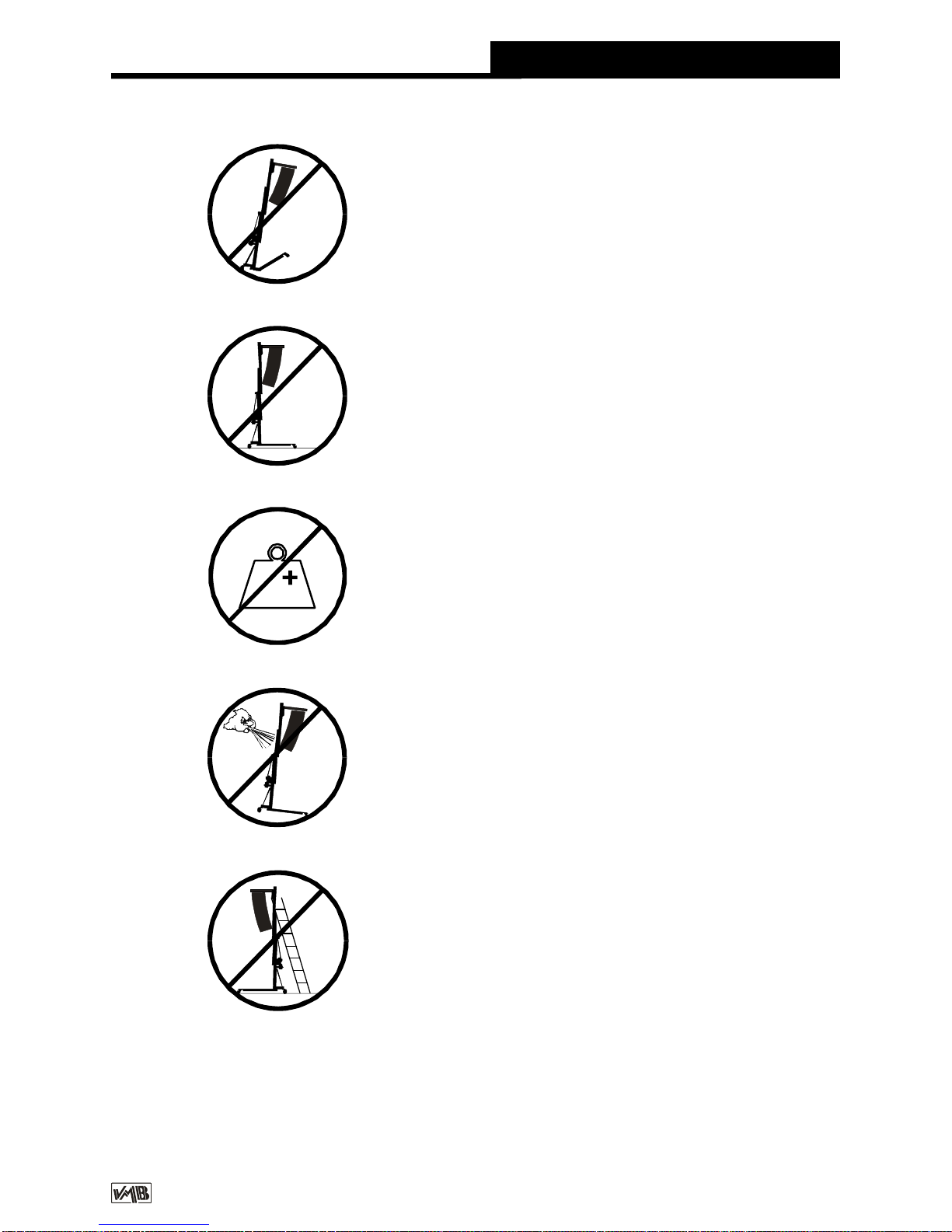
3.5 - Never exceed the maximum weight
indicated on the towerlift and in this ma-
nual.
3.4 - Never elevate the Line Array before
checking it is correctly attached to the lift.
Kgs
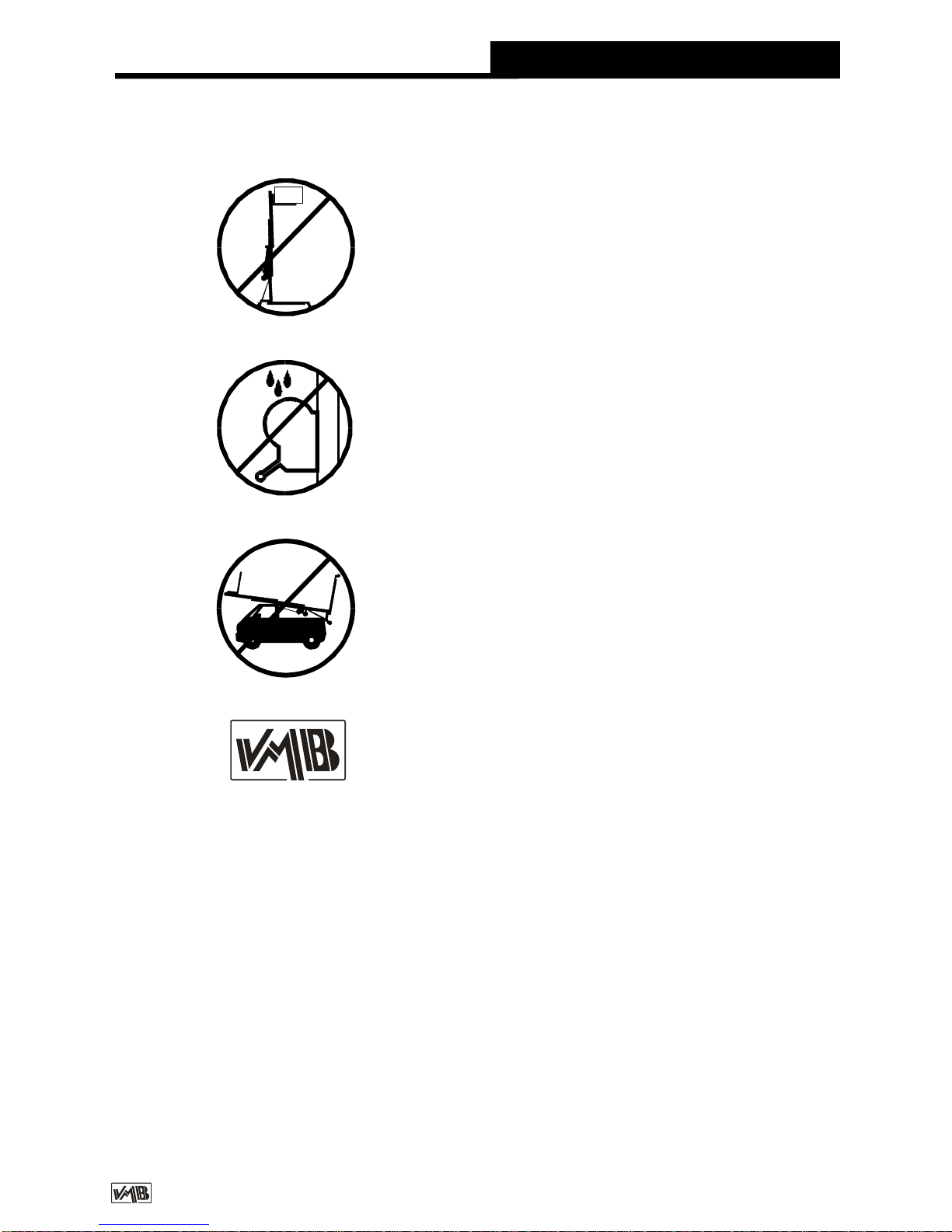
3.6 -Ifthereisexcessivewind,placethelift
on firm ground and attach slings to add
stability. Never attach a sling to a vehicle
or any other element than can move.
3.8 - Be carfeful of any high, obstructions
suchasbalconies,signsetc.Itisimportant
toavoidthepresenceofcablesbeneaththe
workingpositionofthe lift.
3.7 - Do notuse aladder on the lift.

PROLIFTSS.L. V.11.03 - Depósito legal y Copyright 2011. Todos los derechos reservados.
Quick Operation Guide ENGLISH
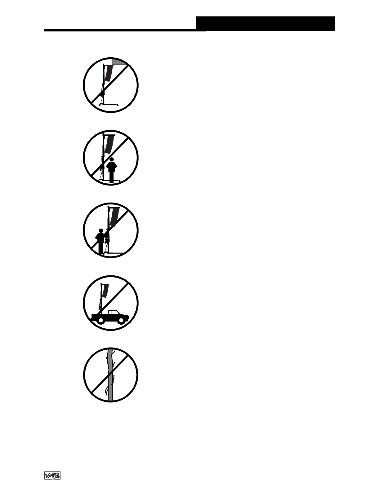
3.11 - Neverusethelifton amobile surface
or on any vehicle.
3.10 - Nevertrytomovetheliftoncetheload
is raised.
3.9 - Neverstandbelowtheraisedmaterial
anddo notallowotherstostandbeneathor
aroundthe workingareaofthelift.
3.12 - Before using the lift check the
conditionofthecable.Thecableshouldnot
be broken or torn. NEVER use defect ca-
bles and ifin doubtchange thecable. Only
use DIN 3060 steel cable 180 Kg/mm2
qualitytorsionresistantcable.
3.13 - Never remove the handle from the
winch if the lift is elevated with load.
PROLIFTSS.L. V.11.03 - Depósito legal y Copyright 2011. Todos los derechos reservados.
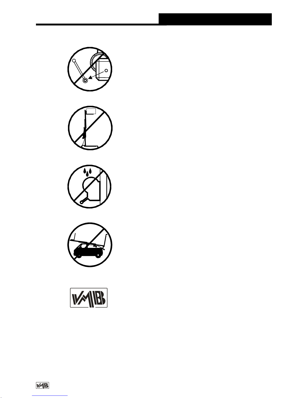
3.16 - All profiles must be lowered before
theliftis transported.
3.15 - Do not greaseor lubricate thebreak
mechanism in the winch. The break discs
have been especially greased with a
special anti heat, pressure material.
Other products must not be used so as to
avoid the break not working effectively.
3.14 - The minimum load for the brake
functioning in the winch is 25kg. Without
this weight the brake will not function.
3.17 - Onlyoriginal sparesmust beused.
ORIGINAL
-25
Quick Operation Guide ENGLISH

PROLIFTSS.L. V.11.03 - Depósito legal y Copyright 2011. Todos los derechos reservados.
4. INSTRUCTIONS.
4.1 - Situate the lift on its transport wheels (T)
upon a flat and stable surface.
When erecting the lift in open air, the risk of
wind is prevalent.
Where wind speeds exceed 30 Km/h it is
essential to tie the lift. 2 lateral eye bolbs (X)
aresituatedatthetopofprofile2,wheretensors
shouldbeattachedandfixedonsecureandfirm
ground (NEVER ON A VEHICULE OR
ANYTHINGTHATCANMOVE).
4.2 -Removetheoutriggersfromtheirtransport
compartments(S)andplacethemintheworking
position (V) ensuring they are fixed with the
security locks (R). The long outriggers are
placed at thefront beneaththe load.The short
outriggers are placed atthe back.
4.3 - Removethe front support bars (BA)from
theirtransportcompartment(S)andplacethem
intheircorrespondingfixedposition(D)oneach
front outrigger and at the top of the first profile
(E) ensuring they are fixed with the pins
provided BU/P1.
To correctly fix the front support bars (BA),
adjust the support of the front outrigger by
turning the stabiliser handel in the necessary
direction.
Insert clips (BU) and security pins (P1).
Adjust the vertical position of the lift with the
stabilisers (Q) turning the handels so that the
spirit level is centred (F).
4.4 - Letgo oftransport securityB,remove the
forksandplacethemhorizontally.
Place thelifting carriageat the required height
so that the Line Array fliying grame can be
attached.
The careful positioning of the front outriggers
enables theLineArray tofit between themand
ease assembley on to the forks.
Support FAS-01 is to be fixed to the forks by
either 1 or 2 points. See fig. 1.
IftheLineArrayfliyiynggramehas4linkpoints
use theFAS-02supportwhichenablestheLine
Array tobe flownfrom4 points, see fig. 2.
BothsupportsFAS-01andFAS-02areinserted
on the forks as follows:
TheLineArraycabinetswillbeattachedtotheir
fliying grame with the angles calculated
according tothe acousticcoveragerequired.
This ensures the Line Array cabinets can be
curved in function with thenecessary degrees
required between them.
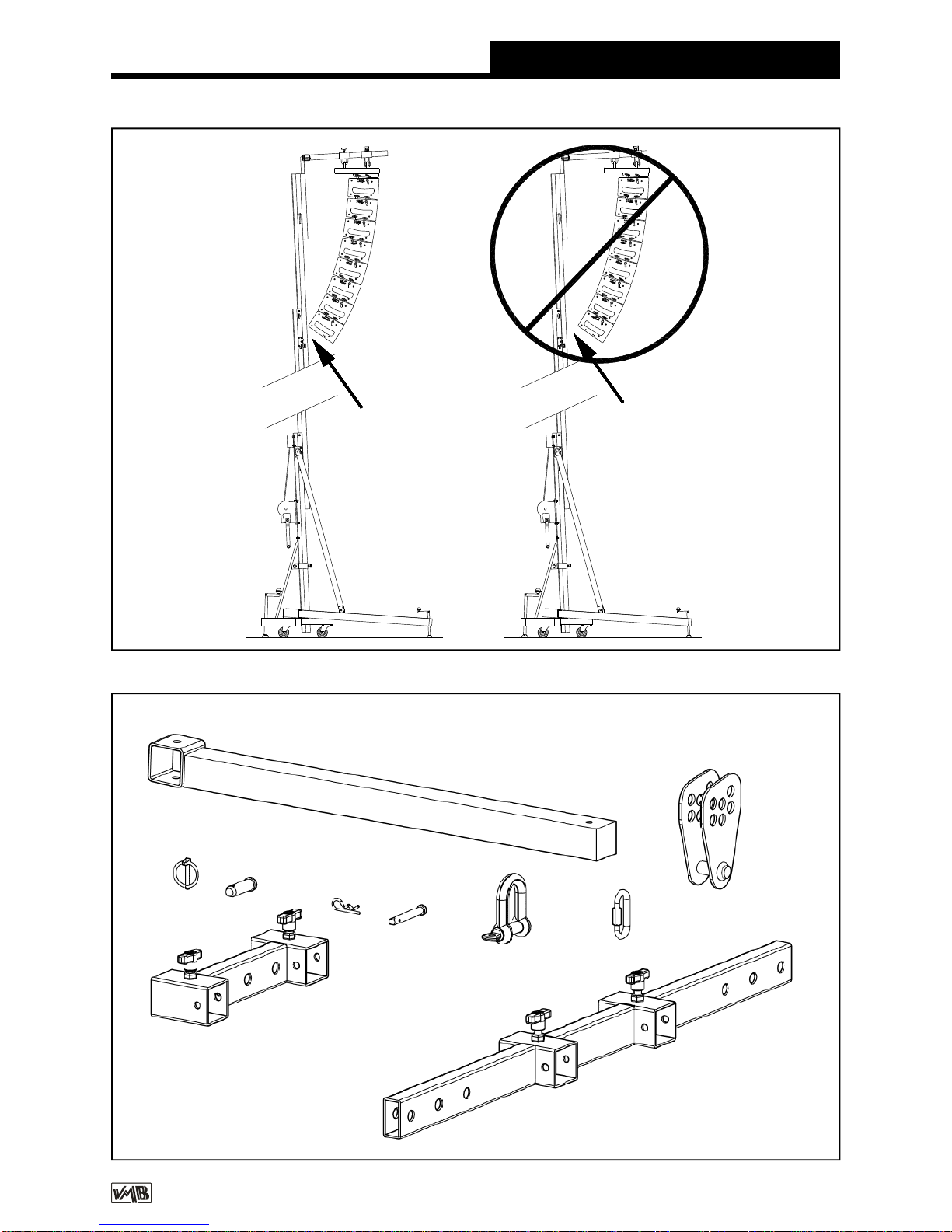
The system should be attached at the
necessary distance to achieve the required
curve.The last cabinet should not hitthe body
of the lift. See fig. 3.
To ensure the maximum security margin it is
necessarry to always attach the LineArray at
the minimum distance possible from the body
ofthelift.Thiswill meanthatthebottomcabinet
is as close as possible to the body of the lift.
See fig. 3A.
To avoid overloading do not seperate
uneccessarily the LineArray from the body of
the lift. See fig. 3B.
Quick Operation Guide ENGLISH

PROLIFTSS.L. V.11.03 - Depósito legal y Copyright 2011. Todos los derechos reservados.
Quick Operation Guide ENGLISH
Fig. 2
Fig. 1
FAS-01
FAS-02 PR-01
PR-01
GS-0,8
MO-C2
GS-0,8
MO-C2
PROLIFTSS.L. V.11.03 - Depósito legal y Copyright 2011. Todos los derechos reservados.
Quick Operation Guide ENGLISH
Fig. 3
TL-A220TL-A220
BA
FAS-01
BC-075L
FAS-02
PAT-02
MO-C2
GS-0,8
MR-PAS
PR-01
MR-SP1 PAS-SP1
PROLIFTSS.L. V.11.03 - Depósito legal y Copyright 2011. Todos los derechos reservados.
Quick Operation Guide ENGLISH
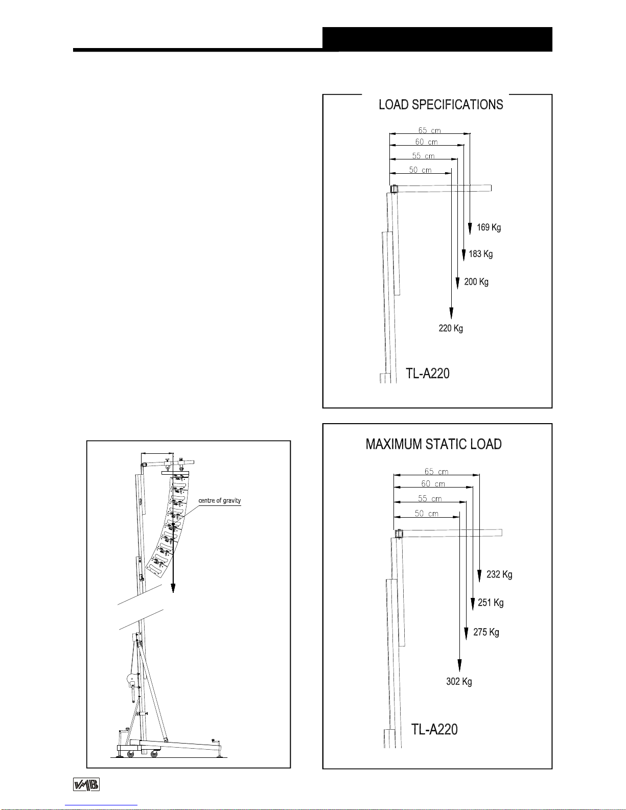
4.5 - Themaximumloadof theTL-A220 is220
Kg with the load point at 50 cm from the lift’s
body.
Theloading pointcapacitycanbe foundonthe
vertical line which marks the centre of gravity
of the Line Array wich is to be flow.
The situation of the centre of gravity depends
upon the chosen LineArray and is necessary
to calculate before use. Never the less, it is
usually situated at the centre ofthe LineArray.
SeeexampleFig.4;8 LynxLX-F6cabinetswith
a total of 200 Kg.
Never overload the lift above the stated
maximumweight of 220 Kg. See Fig. 5.
Fig. 4
Fig . 5
Fig. 6
50 cm
TL-A220
LYNX
LX-F6 (200 Kg.)
PROLIFTSS.L. V.11.03 - Depósito legal y Copyright 2011. Todos los derechos reservados.
4.6 - The TL-A220, can also be used as a
conventional towerlift.
If you are using it as a conventional towerlift
always place the load as close to the body as
possible.
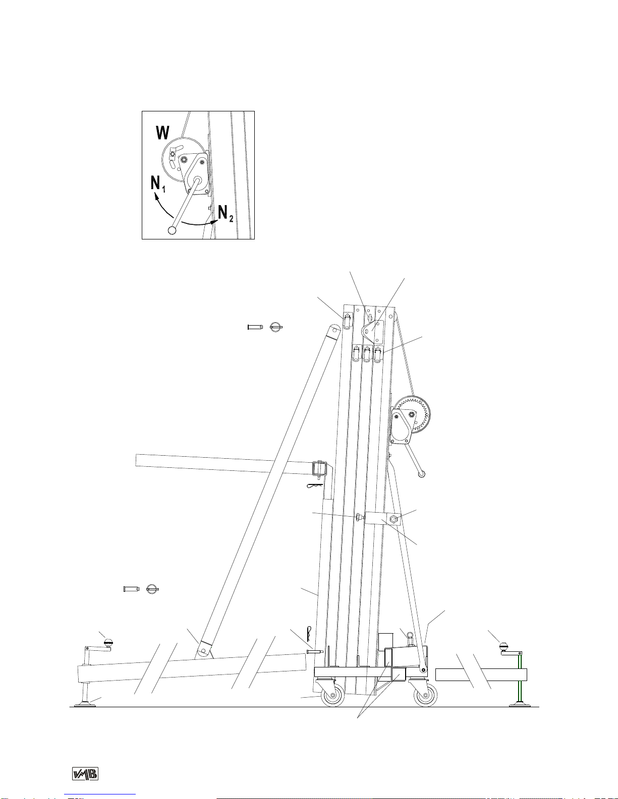
4.7 - Elevating the lift:
OncetheLineArrayisattachedtoitsflyingframe
andinthedesiredpositionontheforksitisready
tobeliftedtotherequiredheight.Turnthewinch
handle in a clockwise direction to elevate the
lift.
Theliftingcarriagewillrisefirst.Whenitreaches
the top the first section will rise along with the
other sections until the ligt has reached its
maximun height of5,5 m.
TheILSandALSenabletheliftto automatically
block the carriage and profiles whilst rising
ensuring that it will never fall. The lift, with the
Linearrayattachedwill remainfixedatalltimes.
Oncethesystemiselevatedtoitsrequiredheight
gently turn the handle in aclockwise direction.
The security systems will ensure that the load
staysfixed andblocked.TheredALSlockswill
beblocked.Thisenablesthecabletobewithout
any force and means it is only used for the
elevationanddescentofthelift.
Thefollowinginstructionswillhelpyoutobring
thesystemdown.
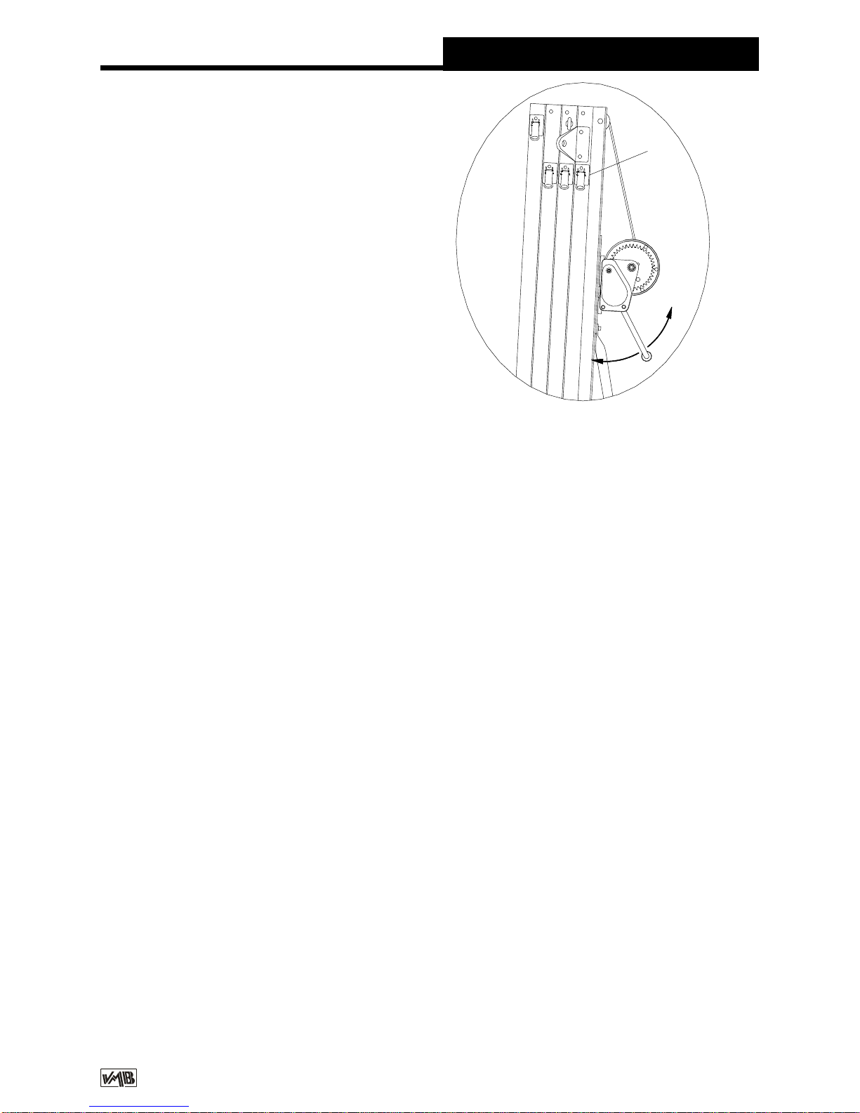
4.8 - Descending the lift:
To bring the lift down you need to first turn the
winchhandleslightlyclockwiseandatthesame
time pullout the redALSlock in (G).(Fig. 7)
Thisreleases the blocking systems.Then turn
the handle anti clockwise, whilst maintaining
theALS lock pulled out in until the profile has
beencompletelylowered.
All redALS locks should be pulled out one by
one whilst the handle is turned anti clockwise
andthe profilesare broughtdown, onebyone.
If you release your finger from the ALS lock it
will automatically block.Inthis case,repeatthe
firstoperation byturningslightlyclockwiseand
thenanticlockwisewhilstalwayspulling thered
ALSlock in.
It isnecessary tocompletelylowereach profile
before starting to lower the next. If you push
anotherredALSlockwithouthavingcompletely
lowered the previous profile the firstprofile will
remainblockedbythesecuritysystemandyou
will not be able to lower it later.
If this happens, elevate the towerlift to the
locked position and free the lock so that you
can commence the descent again until it is
completely lowered.
Finally, release the carriage lockfollowing the
same principle as before and lower it to the
required level to be able to dismount the Line
Array from the lift.
Quick Operation Guide ENGLISH
4.9 - Transport
Once all the profiles are completely lowered
removetheFAS-01 orFAS-02 supportandthe
forks placing them in their horizontal position
facing down. Lower the carriage so that right
forkcan befixedand blockedfor transport (B).
Remove the front support bars( BA) by taking
out the pins (BU). Replace the pins in the top
support ( E ) of the lift’s base profile and also
at the top of each front support bar.
Fig. 7
G
PROLIFTSS.L. V.11.03 - Depósito legal y Copyright 2011. Todos los derechos reservados.
5. MAINTENANCE.
5.1 - Periodically check the condition of the
cable. If a cable is torn or broken it should be
replaced immediately. Do not use the lift if the
cable is not perfect. Only use torsion resistant
steel cable DIN 3060.
5.2 - The lift is supplied completely greased
from the factory. Never the less, we
recommendyouperiodicallygrease(depending
on amount used) the teeth of the winch (CD),
end point ofthe handle (RM),bar (EB) (Fig. 8)
and the profile nylon drums.
ATTENTION: Do not grease orlubricate the
break mechanism.
The brake discs have been greased with a
specialheatandpressureresistantgrease.Do
not use other products.
Quick Operation Guide ENGLISH
7. CERTIFICATIONS
-
ECMachinery Directive
89/392/ECC
and 98/37/ECC
BGV C1 (GUV-VC1) / BGG 912 (GUV-G912)
6. GUARANTEE.
Iftheduringtheguaranteeperiodbecauseof
poorworkmanshiporfaultymaterialsPRO
LIFTSwillrepairorreplaceit.Theguarantee
periodisat2years.Thisguaranteedoesnot
cover damagecausedbyimproperuse,wear
andtearunauthorisedrepairs.Theguarantee
doesnotcoverconsumablesordefectsthat
haveonlyanegligibleeffectonthevalueor
operationoftheelevatortower.
5.3 - All lifts should undergo an annual
technical inspection carried out by an
authorized VMB dealer to check the
certifications and general condition of all the
lift’s elements and security systems involved
in the lift’s use.
5.4 -Onlyuseoriginalsparepartstoguarantee
a continued security level.
Theuserlosesallrightstowarrantyifanyspare
parts other than originals are used or carries
outanymodificationoralterationtothetowerlift.
5.5 - To request a spare part please indicate
the correspondingcode whichcan be found in
thismanual.
Fig. 8
EB EB
CD RM
Place the bars in their transport compartment.
Removetheoutriggers,releasingthelocksand
place in their transport position (S). Turn and
tighten the fixing screws (J). The lift can be
transportedhorizontallybyaddingtheRH-2kit.

PROLIFTSS.L. V.11.03 - Depósito legal y Copyright 2011. Todos los derechos reservados.
Manual de instrucciones ESPAÑOL
CONTENIDO
1. Introducción
2. Datos técnicos
3. Normas de seguridad
4. Instrucciones de uso
5. Mantenimiento
6. Garantía
7. Certificaciones
1. INTRODUCCION
Estimadousuario:
Agradecemos su confianza al adquirir las
torres elevadoras VMB.
Tiene en sus manos un producto de calidad
y fiabilidad contrastadas por la dilatada
experiencia de los usuarios profesionales
en todo el mundo.
Para poder trabajar con este elevador
volando todo tipo de equipos de sonido sin
peligroydeformasegura,leaatentamenteeste
manual, observe los datos técnicos y siga
íntegramente todas las instrucciones de
utilización y seguridad.
Este manual de instrucciones, deberá estar
disponiblepermanentemente junto al elevador.
Todos los elevadores VMB son sometidos a
un constante control de calidad y durísimas
pruebas de verificación, para garantizar la
máxima fiabilidady resistencia.
El elevador TL-A220, ha sido proyectado
especialmente para levantar hasta 5,5metros
dealtura,equiposdesonidotipolinearraycon
un peso de 220 Kg desplazados 50 cm. en
avance respecto al cuerpo de la torre.
Este desplazamiento, es necesario para
poder angular los recintos acústicos los
grados precisos para lograr una perfecta
cobertura de sonorización.
2. DATOS TECNICOS
2.1-TorreelevadoramodeloTL-A220.
2.2 - Diseñada especialmente para levantar
equipos de sonido tipo line array desde el
mismo suelo en sentido vertical a cualquier
altura hasta5,5 m.,conunavance respectoal
cuerpo de la torre de 50 cm.
2.3 - Carga máxima elevable: 220 Kg.despla-
zada50 cmdel cuerpo del elevador.
2.4 - Carga mínima elevable: Puede subir o
bajar sin carga alguna.
2.5 -Altura máxima:5,5 m.
2.6 -Altura plegada: 1,72 m. Altura mínima de
carga : 0,05 m.
2.7 - Superficie de la base : Diagonales 2,78
x 2,78 m.
El elevador, TL-A220, incorporalos sistemas
deseguridadALS (Automatic-Lock-Security),
ILS (Inertia-Lock-Securyty) exclusivosdeVMB,
que garantizan la imposibilidad de caida de
la carga y una total seguridadde utilización.
ATENCION:
No utilice este elevador sin haber leído y
seguir estas instrucciones. En caso contrario,
podría llegar a provocar un grave accidente.
Durante la vida útil del elevador, puede
necesitarpiezas de repuesto. Diríjase en este
caso a su distribuidor habitual.
Solamentedebenutilizarse piezasderepuesto
originales. El usuario perderá todos sus
derechos de garantía si incorpora cualquier
repuesto que no sea original o realiza
cualquier modificación en el elevador.
Para cualquier consulta sobre el elevador,
deberá indicar el número de serie y año de
construcción.

PROLIFTSS.L. V.11.03 - Depósito legal y Copyright 2011. Todos los derechos reservados.
2.8 - Peso de transporte : 95 Kg.
2.9 - Materialdeconstrucción:Cuerpoprincipal
de cuatro tramosmáscarro elevador, en perfil
de aluminio extrusionado 6082-T6. Base,
patas y soportes varios, en perfileria de acero
según DIN 2394. Gatillos de seguridad y
poleas acanaladas en acero ST-37.
2.10 - Sistemas de fijación y seguridad ALS
(Automatic-Lock-Security), ILS (Inertia-Lock-
Securyty) que fijane imposibilitan la caida de
lacargaentodomomento exclusivosdeVMB,
quegarantizanlaelevacióndetodoslostramos
delelevadorfiabilizandoal máximosumanipu-
lación.
Manual de instrucciones ESPAÑOL
2.12 - Cable :Acero según DIN 3060. Calidad
180 Kg/mm2antitorsión. Diámetro 6 mm.
2.13 - Platillosestabilizadoresajustablesenlas
patas, con apoyos antideslizantes de caucho
inyectado.
2.14 - Fijación de las patas con gatillos de
seguridad.
2.15 - Nivelde burbujaparaajustarlaposición
vertical de la torre.
2.16 - Todos los elementos del elevadores-
tán acabados en poliésternegro satinado.
2.17 - Ruedas direccionables para facilitar el
transporte de la torre en posición vertical y
plegada hasta su emplazamiento de trabajo.
3. NORMAS DE SEGURIDAD.
3.1 - El elevador TL-A220 esuna máquina
diseñada para la elevación de cargas en
sentido vertical, NUNCA se debe utilizar
como plataforma elevadora de personas.
3.2- Colocarelelevadorsóloensuperficies
duras y planas, verificando que está en
posición vertical, mediante el nivel de
burbuja (F) situado en el tramo base.
Ajustar sifuera necesarioconlosplatillos
de apoyo (Q), girando la manivela (H) en
el sentido adecuado. Nunca utilice cuñas
ni elementos extraños para equilibrar el
elevador.
!
PROLIFTSS.L. V.11.03 - Depósito legal y Copyright 2011. Todos los derechos reservados.
Manual de instrucciones ESPAÑOL
3.5-Nosedebesobrepasar lacapacidad
de carga máxima indicada en la etiqueta
de características del elevador y en este
manual de instrucciones.
3.4-Nunca se debe elevar una carga
sinantesverificarqueestácorrectamente
apoyada y centrada en los soportes
elevadores adecuados, de forma que el
peso de la carga sólo actúe en sentido
vertical.
3.3 - Comprobar que las patas están
correctamentemontadasysujetasporsus
pasadoresretenedoresdeseguridad.
Kgs
3.6-Siexisteposibilidaddevientofuerteo
en ráfagas, coloque el elevador en suelo
firmeyasegúrelocon laayudadetirantes.
Nunca fije un tirante sobre un vehículo
o cualquier otro elemento que pueda
desplazarse.
3.7-Nouseescalerasencimadelelevador
nilas apoyeen él para realizarningún tipo
de trabajo.
PROLIFTSS.L. V.11.03 - Depósito legal y Copyright 2011. Todos los derechos reservados.
Manual de instrucciones ESPAÑOL
3.11 - No utilice nunca el elevador sobre
una superficie móvil o vehículo.
3.10- Nodesplacenuncaelelevadorsise
encuentra con la carga elevada. No es
aconsejable realizar ningún tipo de
movimiento, ni tan siquiera pequeños
ajustesde posicionamiento.
3.9- Nuncasepongadebajodelacargani
permitala presenciadeotraspersonasen
la zona de trabajo del elevador.
3.8 - Tenga cuidado con todo tipo de
salientes por encima del elevador como
cornisas,balcones,letrerosluminosos,etc...
Es muy importante evitar la presencia de
cablespordebajodelaalturadetrabajodel
elevador.
3.12-Antesdeutilizarelelevador,verifique
el estado del cable. El cable no debe
presentar rotura de hilos o aplastamiento.
NUNCA usecablesdefectuososyencaso
dedudacambieelcable.Sóloutilicecable
de acerosegúnDIN3060.Calidad180Kg/
mm2resistente a la torsión.
PROLIFTSS.L. V.11.03 - Depósito legal y Copyright 2011. Todos los derechos reservados.
3.16 - Para el transporte del elevador hay
que bajar todos los tramos.
3.15-Noengrasenilubriqueelmecanismo
de freno del cabrestante. Los discos de
freno,hansidoengrasadosconunagrasa
especial resistente al calor y la presión.
No deben ser utilizados otros productos
para evitar influir negativamente en el
funcionamiento del freno.
3.14 - La carga mínima para el funciona-
mientodelfrenodelcabrestantesinproble-
mas,esde 25Kg.Sinestacarga mínimael
freno podría no actuar.
3.13 - Nunca desmonte la manivela del
cabrestantesielelevadorestáconcargay
elevado.
3.17 - Solamente deben utilizarse piezas
derepuestooriginales.
Manual de instrucciones ESPAÑOL
ORIGINAL
-25

PROLIFTSS.L. V.11.03 - Depósito legal y Copyright 2011. Todos los derechos reservados.
4. INSTRUCCIONES DE USO.
4.1 - Coloque la torre elevadora apoyada en
sus ruedas de transporte (T) en su emplaza-
mientodetrabajosobreunasuperficieplanay
firme.
En el caso de montar el elevador al aire libre,
existe el riesgo que durante su utilización se
genereviento.
Apartirdeunavelocidaddelvientode30Km/h
es imprescindible arriostrar el elevador, para
lo cual se han previsto dos argollas laterales
defijación (X)situadasen lapartesuperior del
segundo tramo, donde deberán fijarse los
tensores que serán anclados a lugares firmes
yseguros(nuncasobreunvehículoocualquier
otroelementoquepuedadesplazarse).
4.2 - Saque las patas de su soporte para
transporte (S) e insértelas a fondo en sus
alojamientos de trabajo(V) comprobando que
quedan sujetas por los gatillos retenedores
(R). Las patas largas delante, bajo la carga y
las cortas detrás .
4.3-Saquelosbrazosdeapoyofrontales(BA)
del soporte de transporte (S)y colóquelos en
sus puntos de anclaje (D) sobre cada pata
delantera y (E) en los laterales de la parte
superior del tramo base, fijándolos con los
pasadores de seguridad (BU/P1).
Para poder colocar correctamente los brazos
deapoyofrontales(BA),deberá ajustar el apo-
yo de las patas delanteras, girando adecua-
damente las manivelas de los apoyos
regulables de las patas.
Colocar los bulones (BU) y los pasadores de
seguridad (P1).
4.4 - Soltar el seguro de transporte B , sacar
losbrazosdecargayvolvera colocarlosenpo-
siciónhorizontal.
Colocar el carro elevador a laaltura necesaria
parapoder fijarel soportede voladodel equipo
deline array.
La especial disposición de las patas delante-
ras, permite situar el equipo de sonido en el
suelo justo bajo los brazos de carga.
Sobre los brazos de carga, se colocarán
los soportes FAS-01, en el caso de volar un
equipo con fijación central por uno o dos
puntos de vuelo, fig. 1.
En el caso de que el soporte de volado del
equipo de sonido tenga cuatro anclajes
perimetrales, se utilizarán los soportes FAS-
02 que permiten suspender los soportes de
volado desde cuatro puntos, ver fig. 2.
Tanto los soportes FAS-01 como los FAS-02
se colocarán sobre los brazos de carga en la
posición yforma que seindica seguidamente:
Los recintos acústicos del equipo de sonido,
se montarán sobre su soporte de volado con
las angulacionescalculadas parala cobertura
acústica requerida.
Esto condiciona que los recintos de line array
se curvarán hacia detrás en función de los
grados necesarios entre ellos.
El equipo deberá colocarse en consecuencia
sobre los brazos de carga del elevador con el
avance necesario para conseguir que esta
curvatura pueda realizarse, sin que la parte
trasera inferior del último recinto tropiece con
el cuerpo del elevador. Ver fig. 3.
Para conseguir el máximo margen de seguri-
dad, es necesario colocar siempre el equipo
de sonido sobre los brazos de carga del
elevador con el avance mínimo posible, de
forma que la parte trasera inferior del último
recinto del equipo line array se encuentre lo
más cerca posible del cuerpo de la torre. Ver
fig. 3A.
No separar innecesariamente el equipo de
sonido del cuerpo de la torre para evitar una
sobrecarga. Ver fig. 3B.
Manual de instrucciones ESPAÑOL
Other manuals for TL-A220
1
Table of contents
Languages:
Other VMB Lifting System manuals


