Nokia 3510i User manual

PAGE 1 (19) Approved 3.0
Nokia Mobile Phones Customer Care EMEA SQX 00442-en MWy
Technical Services, Repair Concepts Confidential 05.12.2002
3510
NHM-8
3510i
RH-9
Service Manual
Service Level 1&2
Copyright © Nokia Corporation. This material, including documentation and any related computer
programs, is protected by copyright controlled by Nokia Mobile Phones. All rights are reserved.
Copying, including reproducing, storing, adapting or translating, any or all of this material requires
the prior written consent of Nokia Mobile Phones. This material also contains confidential
information, which may not be disclosed to others without the prior written consent of Nokia Mobile
Phones.
Service Manual 3510/3510i Level 1&2 Copyright 2002 © Nokia Corporation

PAGE 2 (19) Approved 3.0
Nokia Mobile Phones Customer Care EMEA SQX 00442-en MWy
Technical Services, Repair Concepts Confidential 05.12.2002
Introduction
The purpose of this document is to help Nokia service levels 1 and 2 workshop
technicians to carry out service to Nokia 3510 and 3510i. This Service Manual is to be
used only by authorized Nokia service partners, and the content of it is confidential.
Please note that Nokia provides also other guidance documents (e.g. Service Bulletins)
for service partners, follow these regularly and comply with the given instructions.
While every endeavor has been made to ensure the accuracy of this document, some
errors may exist. If you find any errors or if you have further suggestions, Nokia should
be notified. Please keep in mind also that this documentation is continuously being
updated and modified, so watch always out for the newest version.
Warnings and Cautions
Please refer to the phone’s user guide for instructions relating to operation, care and maintenance
including important safety information. Note also the following:
Warnings:
1. CARE MUST BE TAKEN ON INSTALLATION IN VEHICLES FITTED WITH ELECTRONIC ENGINE
MANAGEMENT
SYSTEMS AND ANTI–SKID BRAKING SYSTEMS. UNDER CERTAIN FAULT CONDITIONS, EMITTED RF
ENERGY CAN AFFECT THEIR OPERATION. IF NECESSARY, CONSULT THE VEHICLE
DEALER/MANUFACTURER TO DETERMINE THE IMMUNITY OF VEHICLE ELECTRONIC SYSTEMS TO RF
ENERGY.
2. THE HANDPORTABLE TELEPHONE MUST NOT BE OPERATED IN AREAS LIKELY TO CONTAIN
POTENTIALLY EXPLOSIVE ATMOSPHERES EG PETROL STATIONS (SERVICE STATIONS), BLASTING AREAS
ETC.
3. OPERATION OF ANY RADIO TRANSMITTING EQUIPMENT, INCLUDING CELLULAR TELEPHONES, MAY
INTERFERE WITH THE FUNCTIONALITY OF INADEQUATELY PROTECTED MEDICAL DEVICES. CONSULT A
PHYSICIAN OR THE MANUFACTURER OF THE MEDICAL DEVICE IF YOU HAVE ANY QUESTIONS. OTHER
ELECTRONIC EQUIPMENT MAY ALSO BE SUBJECT TO INTERFERENCE.
Cautions:
1. Servicing and alignment must be undertaken by qualified personnel only.
2. Ensure all work is carried out at an anti–static workstation and that an anti–static wrist strap is
worn.
3. Ensure solder, wire, or foreign matter does not enter the telephone as damage may result.
4. Use only approved components as specified in the parts list.
5. Ensure all components, modules screws and insulators are correctly re–fitted after servicing and
alignment. Ensure all cables and wires are repositioned correctly.
6. All PC’s used with NMP Service Software for this produce must be bios and operating system ”Year
2000 Compliant”.
Service Manual 3510/3510i Level 1&2 Copyright 2002 © Nokia Corporation

PAGE 3 (19) Approved 3.0
Nokia Mobile Phones Customer Care EMEA SQX 00442-en MWy
Technical Services, Repair Concepts Confidential 05.12.2002
Table of content
1. EXPLODED VIEW.................................................................................................................................... 5
2. SPARE PARTS LIST................................................................................................................................. 6
3. 3510<>3510I COMPARISON ................................................................................................................... 9
4. SW-UPDATE .............................................................................................................................................. 9
5. GENERAL REPAIR INFORMATION ................................................................................................. 10
6. DISASSEMBLY INSTRUCTIONS ........................................................................................................11
7. QUICK TROUBLE SHOOTER PART1 ............................................................................................... 14
8. QUICK TROUBLE SHOOTER PART2 ............................................................................................... 15
9. QUICK TROUBLE SHOOTER PART3 ............................................................................................... 16
10. ESD PROTECTION REQUIREMENTS........................................................................................... 17
11. SERVICE NOTES................................................................................................................................ 18
12. GONOGO TESTER............................................................................................................................. 19
13. BATTERYTESTER ............................................................................................................................. 19
Service Manual 3510/3510i Level 1&2 Copyright 2002 © Nokia Corporation

PAGE 4 (19) Approved 3.0
Nokia Mobile Phones Customer Care EMEA SQX 00442-en MWy
Technical Services, Repair Concepts Confidential 05.12.2002
Change History
Originator Status Version No. Date Comments
MWy Draft 0.1 04.04.2002 Initial draft
MWy Approved 1.0 22.05.2002 approval
Mwy Approved 2.0 05.06.2002 Corrections in Trouble Shooter
DJK Approved 3.0 05.12.2002 3510I & Level 2 implementation
Service Manual 3510/3510i Level 1&2 Copyright 2002 © Nokia Corporation

PAGE 5 (19) Approved 3.0
Nokia Mobile Phones Customer Care EMEA SQX 00442-en MWy
Technical Services, Repair Concepts Confidential 05.12.2002
1. EXPLODED VIEW
Description: See corresponding ITEM/CIRCUIT REF of the SPL (Spare Parts List)
Service Manual 3510/3510i Level 1&2 Copyright 2002 © Nokia Corporation

PAGE 6 (19) Approved 3.0
Nokia Mobile Phones Customer Care EMEA SQX 00442-en MWy
Technical Services, Repair Concepts Confidential 05.12.2002
2. SPARE PARTS LIST
ITEM/
CIRCUIT REF.
QTY
PART NO PART NAME USED IN
A901 1 9517120 BB SHIELD LID 3510 & 3510i
I003 6 6290107 SCREWS 1.8X7.0 FE T6+ 3510 & 3510i
I004 1 4850247 DISPLAY ASSEMBLY 96X65 3510
I004 1 4850277 DISPLAY ASSEMBLY POPEYE 3510i
I025 1 XXXXXXX DOMESHEET 3510 & 3510i
I006 1 5140243 SALT SPEAKER 3510 & 3510i
I007 1 5409159 SM SYSTEM CONN 3510 & 3510i
I008 1 6800053 VIBRA MOT ASSY 1.3V 115MA 9500RPM 3510 & 3510i
I009 1 9517122 SIM CARD SUPPORT 3510 & 3510i
I010 1 5400253 BATTERY CONN 4 POL SPRING 3510 & 3510i
I011 1 9790514 POWERKEY, LIME GREEN 3510
I011 1 9790895 POWERKEY, ORANGE 3510i
I014 1 9510854 RELEASE SPRING CLOSED 3510 & 3510i
I018 1 5140067 SPEAKER+SPRING 103+-3DB 32R d13.2 3510 & 3510i
I019 1 9517121 METAL FRAME ASSEMBLY 3510 & 3510i
I021 1 5140201 MIC+BOOT ASSY -42+-3DB 3510 & 3510i
SOLDERING COMPONENTS ONLY FOR LEVEL 2
ITEM/
CIRCUIT REF.
QTY
PART NO PART NAME USED IN
F100 1 5119019 SM FUSE F 1.5A 32V 0603 1.5A 3510 & 3510i
S300 1 5209001 SM SW TACT SPST 12V 50MA SIDE KEY 3510 & 3510i
V301 1 4860401 LED LNJ322W830NK 575NM 90DEG TBSF 3510
V302 1 4860401 LED LNJ322W830NK 575NM 90DEG TBSF 3510
V308 1 4860401 LED LNJ322W830NK 575NM 90DEG TBSF 3510
V309 1 4860401 LED LNJ322W830NK 575NM 90DEG TBSF 3510
V301 1 4860411 HIGH BRIGHT WHITE TBSF LED 3510i
V302 1 4860411 HIGH BRIGHT WHITE TBSF LED 3510i
V308 1 4860421 LOW BRIGHT WHITE TBSF LED HDB12 3510i
V309 1 4860421 LOW BRIGHT WHITE TBSF LED HDB12 3510i
Service Manual 3510/3510i Level 1&2 Copyright 2002 © Nokia Corporation

PAGE 7 (19) Approved 3.0
Nokia Mobile Phones Customer Care EMEA SQX 00442-en MWy
Technical Services, Repair Concepts Confidential 05.12.2002
VARIANT PARTS
ITEM/
CIRCUIT REF.
QTY
PART NO PART NAME USED FOR
I001 1 9490588 A-COVER Assembly DARK BLUE 3510
I001 1 9490589 A-COVER Assembly WHITE 3510
I001 1 9490590 A-COVER Assembly BURGUNDY 3510
I002 1 9794055 KEYMAT LATIN 3510
I002 1 9794104 KEYMAT ARABIC 3510
I002 1 9794105 KEYMAT GREEK 3510
I002 1 9794106 KEYMAT HEBREW 3510
I002 1 9794107 KEYMAT CYRILIC 3510
I017 1 9490585 B-COVER ASSEMBLY LIGHT BLUE 3510
I017 1 9490587 B-COVER ASSEMBLY BURGUNDY 3510
I017 1 9490586 B-COVER ASSEMBLY GREEN 3510
VARIANT PARTS
ITEM/
CIRCUIT REF.
QTY
PART NO PART NAME USED FOR
I001 1 9458634 A-COVER ASSY POPEYE GREEN E&A 3510i
I001 1 9458857 A-COVER ASSY POPEYE BLUE E&A 3510i
I001 1 9458858 A-COVER ASSY POPEYE BEIGE E&A 3510i
I002 1 9790839 KEYMAT, LATIN 3510i
I002 1 9790840 KEYMAT, CYRILLIC 3510i
I002 1 9790841 KEYMAT, GREEK 3510i
I002 1 9790842 KEYMAT, HEBREW 3510i
I002 1 9790843 KEYMAT, ARABIC 3510i
I017 1 9491056 B-COVER ASSY POPEYE WHITE E&A 3510i
I017 1 9491057 B-COVER ASSY POPEYE BLUE E&A 3510i
I017 1 9491068 B-COVER ASSY POPEYE RED E&A 3510i
Service Manual 3510/3510i Level 1&2 Copyright 2002 © Nokia Corporation

PAGE 8 (19) Approved 3.0
Nokia Mobile Phones Customer Care EMEA SQX 00442-en MWy
Technical Services, Repair Concepts Confidential 05.12.2002
SWAP UNITS
QTY
PART NO PART NAME USED FOR
0074112 NHM-8NX N3510 SWAP ENGINE EUROPE 3510
0074113 NHM-8NX N3510 SWAP ENGINE RUSSIA 3510
0074114 NHM-8NX N3510 SWAP ENGINE TURKEY 3510
0074115 NHM-8NX N3510 SWAP ENGINE CS-SK 3510
0074116 NHM-8NX N3510 SWAP ENGINE FRANCE 3510
0074117 NHM-8NX N3510 SWAP ENGINE POLAND 3510
0076275 NHM-8NX N3510 SWAP SOUTH AFRICA 3510
SWAP UNITS
QTY
PART NO PART NAME USED FOR
0075985 RH-9 N3510i SWAP ENGINE EUROPE 3510i
0075986 RH-9 N3510i SWAP ENGINE RUSSIA 3510i
0075987 RH-9 N3510i SWAP ENGINE TURKEY 3510i
0075988 RH-9 N3510i SWAP ENGINE FRANCE 3510i
0075989 RH-9 N3510i SWAP ENGINE CZHECH 3510i
0075990 RH-9 N3510i SWAP ENGINE POLAND 3510i
0076274 RH-9N3510i SWAP ENGINE SOUTH AFRICA 3510i
SERVICE TOOLS
TYPE QTY
PART NO PART NAME USED FOR
1 0271738 BLC-2 BATT.BLOCK LI-ION 950MAH 3510 & 3510i
1 0271582 DCV-10 DESKTOP STAND 3510 & 3510i
1 0272169 AC TRAVEL CHARGER ACP-8E (EURO) 3510 & 3510i
1 0272172 AC TRAVEL CHARGER ACP-8X (UK) 3510 & 3510i
1 0271503 HDC-5 HEADSET 3510 & 3510i
1 0775304 FLA-23 POS FLASH LOADING ADAPTER 3510 & 3510i
1 0730218 XCS-1 SERVICE CABLE 3510 & 3510i
1 0080541 FLS-4S SALES PACK E&A 3510 & 3510i
1 0770431 SRT-6 OPENING TOOL 5510 3510 & 3510i
Service Manual 3510/3510i Level 1&2 Copyright 2002 © Nokia Corporation

PAGE 9 (19) Approved 3.0
Nokia Mobile Phones Customer Care EMEA SQX 00442-en MWy
Technical Services, Repair Concepts Confidential 05.12.2002
3. 3510<>3510I COMPARISON
There is one difference between these two products. The 3510i is equipped with a color display. All
another mechanical parts are identical (see Spare Parts Lists).
4. SW-UPDATE
To use FLS-4S Flash Dongle you have to follow the user guide inside the sales package. Please
check always the latest version of flash software, which is available on Partner Website.
Flash Concept – (Point of Sales)
Note that ACF-8 charger is inside FLS-4S sales pack and cannot be ordered separately.
.
It is very important to follow this insertion
and removal procedure, otherwise the
contact pins of Flash Adapter will be
damaged.
Insert the Flash Adapter FLA-23 like a battery, start
at the battery connector site.
Now, push down the bottom side of the phone, do
not use too much force.
When removing the Flash Adapter, always start
from the bottom side of the unit.
Take away the unit now.
Description: See corresponding ITEM/CIRCUIT REF of the SPL (Spare Parts List)
Service Manual 3510/3510i Level 1&2 Copyright 2002 © Nokia Corporation

PAGE 10 (19) Approved 3.0
Nokia Mobile Phones Customer Care EMEA SQX 00442-en MWy
Technical Services, Repair Concepts Confidential 05.12.2002
5. GENERAL REPAIR INFORMATION
In this section the technician will get some general hints how to carry out repairs:
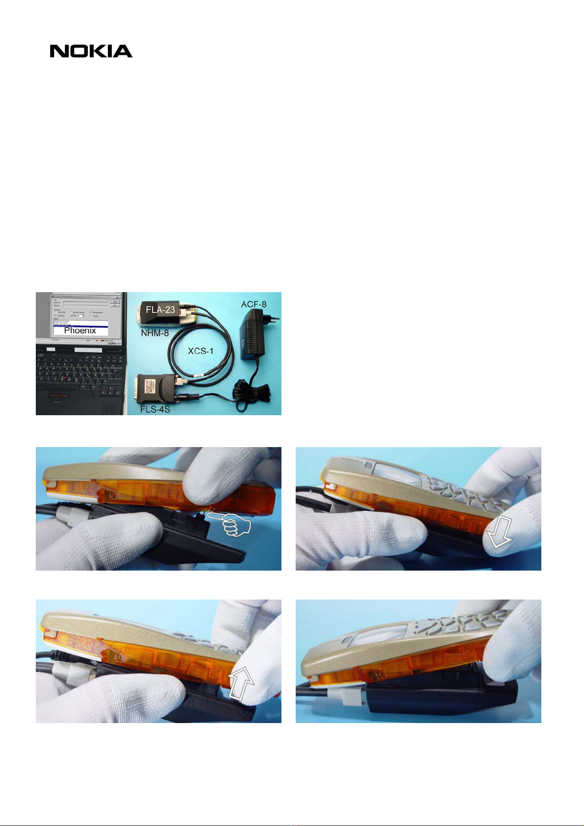
o Before starting the repair you must take care of ESD precautions like being in your ESD-area and
connecting your wristband.
o Use gloves to avoid corrosion and fingerprints.
o Protect windows and displays with a foil to avoid dust and scratches.
o When cleaning the pads you have to use a soft cloth and isopropanol. It is not allowed to use a glass fiber
pencil because it scratches the surface and will lead later on to corrosion.
o Mechanical parts, which didn’t repair the failure, can be reused, if they are not soldered.
o Use always original Nokia parts or accessories.
o Meet the torque requirements when assembling the unit (see also the document “torques for transceiver
assembly” on Partner Websites).
o Always use your own equipment for testing where you are sure that it works. E.g. if the customer
complains about charger function, please test the phone with your own charger to be sure if phone or
charger causes the malfunction.
o When doing the Faultlogger entries, always note the Item code, which caused the malfunction. Also, fill in
the appropriate part code from the assembly, if needed.
o Please be aware that some malfunctions could be software related and solved by an update
Following General Service Bulletins have to be followed:
SB-055 Common notice for good ventilation
SB-089: Don’t try to repair prototypes (indicated on Typelabel).
SB-107: Be sure that you have minimum hardware requirements in place.
SB-115: Handling of liquid damages.
SB-121: If one of your service tools causes malfunction, return the defective part.
SB-122: Soldering with manual hot air gun is totally forbidden because of the very sensitive µBGA
components and µVia technology.
SB-124 Service Policy for packaging serviced products
SB-131: Check these guidelines when refurbishing products.
SB-132: You can use a Golden Phone for inspecting your measuring equipment.
Please check Nokia Partner Web Site (PWS) for latest news and files on a regular basis.
This legend is valid for all parts of the Quick Trouble Shooter
Follow the steps until the problem is solved. If this doesn’t help, you are not authorized to go forward.
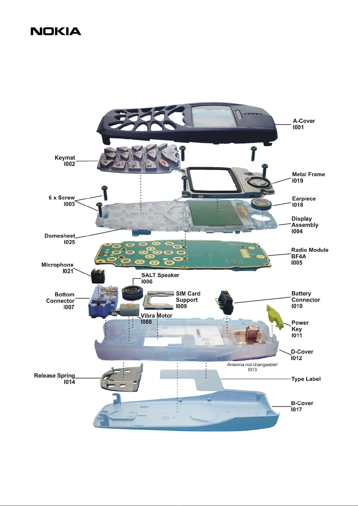
Only underlined components ( e.g. I007) can be changed.
Follow the arrows step by step
Pads or contacts: Check optical and mechanical condition as well as corrosion. Clean if
necessary.
Measure component for electrical functionality and change, if needed.
No more actions possible, send product to the appropriate service partner with higher
service level.
Service Manual 3510/3510i Level 1&2 Copyright 2002 © Nokia Corporation

PAGE 11 (19) Approved 3.0
Nokia Mobile Phones Customer Care EMEA SQX 00442-en MWy
Technical Services, Repair Concepts Confidential 05.12.2002
6. DISASSEMBLY INSTRUCTIONS
Release the A-Cover from the bottom side of the
unit.
Take away the A-Cover.
Also, protect the inner part of the window with a
foil. The Keymat is loose inside the A-Cover.
Unscrew the six T6 screws, using the order shown. For
assembly, the reverse order and a Torx T6 PLUS with a
torque of 28 Ncm has to be used.
When releasing the side clips of the D-Cover you can
use the SRT-6.
This is the second clip.
Take away the Display Assembly (UI module) and
avoid touching the pads.
There are two snaps on each side of the Metal
Frame.
Service Manual 3510/3510i Level 1&2 Copyright 2002 © Nokia Corporation

PAGE 12 (19) Approved 3.0
Nokia Mobile Phones Customer Care EMEA SQX 00442-en MWy
Technical Services, Repair Concepts Confidential 05.12.2002
Remove the Metal Frame.
If you hold the UI module upside down, the Speaker
drops out of its hollow.
The next step is to take away the Radio Module. Take
care not to damage the LED´s.
Lift up the Battery Connector with your fingers.
Remove the Power Key.
To loosen the System Connector you can use SRT-6
opening tool. Take care not to scratch the D-Cover or
the connector housing.
The Microphone can be changed separately. To
remove it from the connector housing, you have to
push it with e.g. Torx Driver.
When re-assembling the Microphone remember the
right direction. The opening of the Microphone has
to point to the opening of the connector housing.
Service Manual 3510/3510i Level 1&2 Copyright 2002 © Nokia Corporation

PAGE 13 (19) Approved 3.0
Nokia Mobile Phones Customer Care EMEA SQX 00442-en MWy
Technical Services, Repair Concepts Confidential 05.12.2002
The SALT Speaker is taped to the D-Cover and can be
removed with a straight bladed screwdriver.
If you need to change the Vibra Motor, strong
tweezers or pliers can be taken.
Remove the SIM Card Support using this way.
The Release Spring is locked on two sides. Use a
screwdriver to unlock the two snaps.
After releasing the two hooks, you can remove the
Release Spring easily.
Service Manual 3510/3510i Level 1&2 Copyright 2002 © Nokia Corporation

PAGE 14 (19) Approved 3.0
Nokia Mobile Phones Customer Care EMEA SQX 00442-en MWy
Technical Services, Repair Concepts Confidential 05.12.2002
7. QUICK TROUBLE SHOOTER PART1
Service Manual 3510/3510i Level 1&2 Copyright 2002 © Nokia Corporation

PAGE 15 (19) Approved 3.0
Nokia Mobile Phones Customer Care EMEA SQX 00442-en MWy
Technical Services, Repair Concepts Confidential 05.12.2002
8. QUICK TROUBLE SHOOTER PART2
Service Manual 3510/3510i Level 1&2 Copyright 2002 © Nokia Corporation

PAGE 16 (19) Approved 3.0
Nokia Mobile Phones Customer Care EMEA SQX 00442-en MWy
Technical Services, Repair Concepts Confidential 05.12.2002
9. QUICK TROUBLE SHOOTER PART3
Service Manual 3510/3510i Level 1&2 Copyright 2002 © Nokia Corporation

PAGE 17 (19) Approved 3.0
Nokia Mobile Phones Customer Care EMEA SQX 00442-en MWy
Technical Services, Repair Concepts Confidential 05.12.2002
10. ESD PROTECTION REQUIREMENTS
Electrostatic discharge can easily damage the sensitive components of
electronic products. Therefore every Service Partner has to take care of
at least some precautions like ESD restricted area, floor, table, covering,
chair(s), shoes or arm wrist.
Please refer to the Partner Website document
ESD protection requirements for NMP Service Level 1/2 Service Suppliers
example configuration of an epa-area
source: www.armeka.com
example configuration of a workbench
source: www.warmbier.com
example workbench and testers
source: http://www.armekaengineering.com
Service Manual 3510/3510i Level 1&2 Copyright 2002 © Nokia Corporation

PAGE 18 (19) Approved 3.0
Nokia Mobile Phones Customer Care EMEA SQX 00442-en MWy
Technical Services, Repair Concepts Confidential 05.12.2002
11. SERVICE NOTES
We recommend using Service Notes when shipping phones to other Service Partners. It
prevents the product from scratches, it is ESD-neutral and has the possibility to give
valuable feedback of the fault symptom through a structured form.
Please refer to the document Service Notes for faulty NMP transceiver on Partner
Website to get further information.
Service Manual 3510/3510i Level 1&2 Copyright 2002 © Nokia Corporation

PAGE 19 (19) Approved 3.0
Nokia Mobile Phones Customer Care EMEA SQX 00442-en MWy
Technical Services, Repair Concepts Confidential 05.12.2002
12. GONOGO TESTER
The Acterna/Wavetek GoNoGo Tester
has to be used to carry out the final
test after your service action to
guarantee the functionality of the
phone.
Please refer to the actual
information in the Nokia Care
Point Extranet within the Partner
Website.
13. BATTERYTESTER
The Astratec battery tester
lets you test the capacity
of Nokia batteries.
Please refer to the actual
information in the Nokia
Care Point Extranet
within the Partner
Website.
Service Manual 3510/3510i Level 1&2 Copyright 2002 © Nokia Corporation
Other manuals for 3510i
3
This manual suits for next models
3
Table of contents
Other Nokia Cell Phone manuals

Nokia
Nokia N97 User manual

Nokia
Nokia 5800 - XpressMusic Smartphone - WCDMA User manual

Nokia
Nokia 1508I Quick start guide

Nokia
Nokia N900 User manual

Nokia
Nokia C6-01 User manual

Nokia
Nokia 6610i - Cell Phone 4 MB User manual

Nokia
Nokia 2126i User manual

Nokia
Nokia N91 User manual

Nokia
Nokia 6212 classic Parts list manual

Nokia
Nokia 2228 User manual