Nonin 2500A PalmSAT User manual

Operator’sManual
Pulse Oximeter
with Alarms
2500A PalmSAT
®
1
English
0123

AbouttheManual
There are many precautions for use throughout this manual. Read them carefully;
they are important to the use of the product.
The information in this manual has been carefully checked and is believed to be
accurate. In the interest of ongoing product development, NONIN reserves the
right to make changes and improvements to this manual and the products it
describes at any time, without notice or obligation.
CAUTION! Federal law (USA) restricts this device to sale by or on the
order of a physician.
CAUTION! Read this entire manual carefully before using the 2500A
PalmSAT Pulse Oximeter with Alarms.
Nonin Medical, Inc.
13700 1st Avenue North
Plymouth, Minnesota 55441-5443
USA
(763) 553-9968
(800) 356-8874 (USA and Canada)
Fax (763) 553-7807
E-mail: [email protected]
www.nonin.com
Authorized EC Representative:
MPS, Medical Product Service GmbH
Borngasse 20
D-35619 Braunfels, Germany
References to “NONIN” in this manual shall imply Nonin Medical, Inc.
NONIN, PalmSAT, Flexi-Form, FlexiWrap, and nVISION are registered
trademarks or trademarks of Nonin Medical, Inc.
© 2005 Nonin Medical, Inc.
0123

Guide to Symbols 1
GuidetoSymbols
This table describes the symbols that are found on the Model 2500A.
Regulatory Symbols
Attention: See Instructions for Use or related materials.
Type BF Applied Part
(Patient isolation from electrical shock).
UL Mark for Canada and the United States with respect to
electric shock, fire, and mechanical hazards only in accordance with
UL 60601-1 and CAN/CSA C22.2 No. 601.1.
CE Marking indicating conformance to EC directive No. 93/42/
EEC concerning medical devices.
Serial Number (located under the back cover).
Protected against vertically falling water drops when enclosure is
tilted up to 15 degrees per IEC 60529.
Indicates separate collection for electrical and electronic equipment
(WEEE).
!
C
L
A
S
S
I
F
I
E
D
U
S
CUL
0123
SN
IPX2

2Precautions for Use
PrecautionsforUse
Indications for Use
The NONIN®Model 2500A PalmSAT®Pulse Oximeter with Alarms is indicated
for use in measuring and displaying functional oxygen saturation of arterial
hemoglobin (SpO2) and pulse rate for adult, pediatric, and neonatal patients. The
2500A is intended for continuous monitoring and/or spot-checking of patients
during both motion and no-motion conditions, and for patients who are well or
poorly perfused.
Contraindications
•Do not use the 2500A PalmSAT in an MRI environment.
•Explosion Hazard: Do not use the 2500A in an explosive atmosphere.
Warnings
•The 2500A is intended only as an adjunct in patient assessment. It must be
used in conjunction with other methods of assessing clinical signs and
symptoms.
•Use only NONIN-manufactured pulse oximeter sensors. These sensors are
manufactured to meet the accuracy specifications for NONIN Pulse
Oximeters. Using other manufacturers’ sensors may cause improper pulse
oximeter performance.
•As with all medical equipment, carefully route patient cabling to reduce the
possibility of patient entanglement or strangulation.
•Discontinue use of adhesive tape strips if the patient exhibits an allergic
reaction to the adhesive material.
•Donotstretchtheadhesivetapewhileapplyingthepulseoximetersensor.This
may cause inaccurate readings or skin blisters.
•General operation of the 2500A may be affected by the use of an
electrosurgical unit (ESU).
•Because operating environments vary, use caution to ensure that all audible
alarms and indicators can be heard. Users must determine the acceptable
audible distance of all alarms.
•Do not place the 2500A in an environment where its speaker opening may
become blocked; alarms may become muffled or inaudible.
•Turning off the 2500A’s alarm volume creates a situation that is not compliant
with relevant safety standards. The alarm silence indicator is lit solid when the
alarm volume is turned off or set below 45 dBA.
•Do not use a damaged sensor.

Precautions for Use 3
•When a system fault occurs, the patient will no longer be monitored.
•At critically low battery capacity, the patient will no longer be monitored.
•Blood flow restrictors (e.g., blood pressure cuffs) may hinder pulse
measurements. Remove any objects that may hinder the performance of the
pulse oximeter.
•This device should not be used adjacent to or stacked with other equipment.
If adjacent or stacked use is necessary, the device should be observed carefully
to verify normal operation.
•The use of accessories, sensors, and cables other than those listed in this
manual may result in increased emission and/or decreased immunity of this
device.
Cautions
•Federal law (USA) restricts this device to sale by or on the order of a physician.
•Read this entire manual carefully before using the 2500A.
•Before use, carefully read the package insert provided with the sensors.
•Inspect the sensor application site at least every 6 to 8 hours to ensure correct
sensor alignment and skin integrity. Patient sensitivity to sensors may vary due
to medical status or skin condition.
•The 2500A is not an apnea monitor.
•Verify that all visible indicators illuminate and that an audible indicator sounds
during the startup (initialization) sequence. If any indicator is not lit or the
audible indicator does not sound, do not use the 2500A. Contact NONIN
Customer Support for assistance.
•The presence of a defibrillator may interfere with the performance of this
device.
•Some nail polish colors (particularly dark shades) or artificial nails may reduce
light transmission and affect SpO2accuracy. Remove any nail polish or
artificial nails before using the 2500A.
•The 2500A may not work on all patients. If you are unable to achieve stable
readings, discontinue use.
•The 2500A has motion tolerant software that minimizes the likelihood of
motion artifact being misinterpreted as good pulse quality. In some
circumstances, however, the 2500A may still interpret motion as good pulse
quality. Minimize patient motion as much as possible.
•The 2500A is designed to determine the percentage of arterial oxygen
saturation of functional hemoglobin. Significant levels of dysfunctional
hemoglobin, such as carboxyhemoglobin or methemoglobin, may affect the
accuracy of the measurement.
(Continued)Warnings

4Precautions for Use
•Cardiogreen and other intravascular dyes, depending on the concentration,
may affect the accuracy of the SpO2measurement.
•Ear Clip and Reflectance sensors are not recommended for pediatric or
neonatal use. The accuracy of these sensors has not been established for
pediatric or neonatal use.
•Do not immerse the 2500A or NONIN sensors in liquid, and do not expose
the device or components to excessive moisture or liquids.
•Do not use caustic or abrasive cleaning agents on the 2500A or the sensors.
•The oximeter sensor might not work on cold extremities due to reduced
circulation. Warm or rub the finger to increase circulation, or reposition the
sensor.
•The 2500A isaprecisionelectronic instrument and mustberepaired bytrained
NONIN personnel only.
•Replace the batteries as soon as possible after a low battery indication. Always
replace the batteries with fully-charged batteries.
•Use only NONIN-specified battery types with this device.
•Do not mix fully charged and partially charged batteries at the same time. This
may cause the batteries to leak.
•Do not remove any covers other than the battery cover when replacing
batteries. There are no user-serviceable parts inside other than the replaceable
batteries.
•Follow local governing ordinances and recycling instructions regarding
disposal or recycling of the device and device components, including batteries.
•Batteries may leak or explode if used or disposed of improperly.
•Remove the batteries if the 2500A will be stored for more than 1 month.
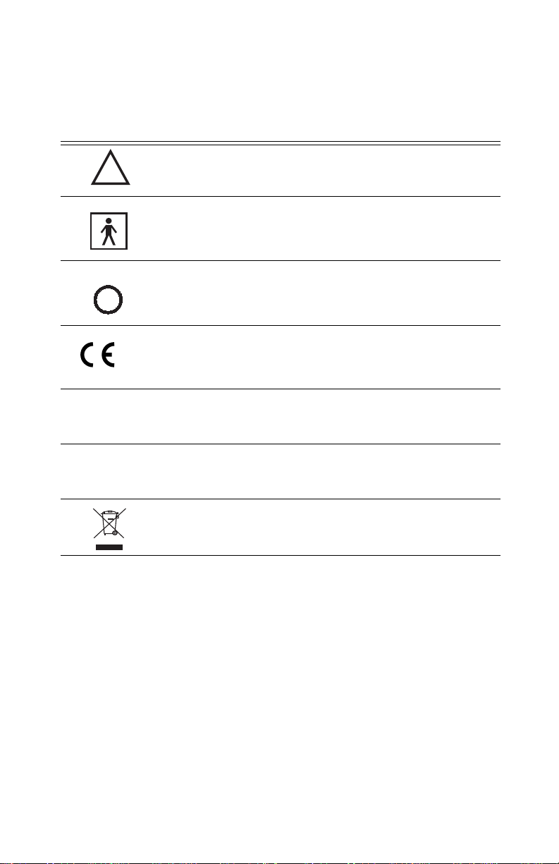
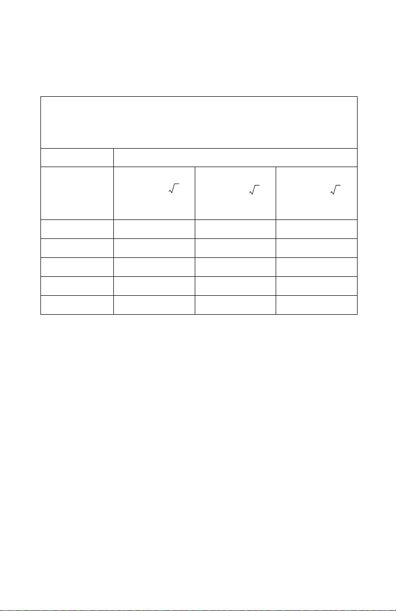
•This equipment complies with International Standard EN 60601-1-2:2001 for
electromagnetic compatibility for medical electrical equipment and/or
systems. This standard is designed to provide reasonable protection against
harmful interference in a typical medical installation. However, because of the
proliferation of radio-frequency transmitting equipment and other sources of
electrical noise in healthcare and other environments, it is possible that high
levels of such interference due to close proximity or strength of a source might
disrupt the performance of this device. Medical electrical equipment needs
special precautions regarding EMC, and all equipment must be installed and
put into service according to the EMC information specified in this manual.
•In compliance with theEuropean Directive on Waste Electrical and Electronic
Equipment (WEEE) 2002/96/EC, do not dispose of this product as unsorted
municipal waste. This device contains WEEE materials; please contact your
distributor regarding take-back or recycling of the device. If you are unsure
how to reach your distributor, please call Nonin for your distributor’s contact
information.
•Portable and mobile RF communications equipment can affect medical
electrical equipment.
Cautions (Continued)

Precautions for Use 5
Manufacturer’s Declaration
Refer to the following tables for specific information regarding this device’s
compliance to IEC Standard 60601-1-2.
Table 1: Electromagnetic Emissions
Emissions Test Compliance Electromagnetic Environment—Guidance
This device is intended for use in the electromagnetic environment specified below. The customer
and/or user of this device should ensure that it is used in such an environment.
RF Emissions
CISPR 11 Group 1 This device uses RF energy only for its internal
function. Therefore, its RF emissions are very
low and are not likely to cause any interference
in nearby electronic equipment.
RF Emissions
CISPR 11 Class B This device is suitable for use in all establish-
ments, including domestic and those directly
connected to the public low-voltage power
supply network that supplies buildings used for
domestic purposes.
Harmonic Emissions
IEC 61000-3-2 N/A
Voltage Fluctuations/
Flicker Emissions
IEC 61000-3-3
N/A

6Precautions for Use
Table 2: Electromagnetic Immunity
NOTE: UTis the AC mains voltage before application of the test level.
Immunity Test IEC 60601 Test
Level Compliance
Level Electromagnetic
Environment—
Guidance
This device is intended for use in the electromagnetic environment specified below. The customer
and/or user of this device should ensure that it is used in such an environment.
Electrostatic
Discharge
(ESD)
IEC 61000-4-2
±6 kV contact
±8 kV air ±6 kV contact
±8 kV air Floors should be wood, con-
crete, or ceramic tile. If floors
are covered with synthetic
material, the relative humidity
should be at least 30%.
Electrical Fast
Transient/Burst
IEC 61000-4-4
±2 kV for power
supply lines
±1 kV for input/
output lines
±2 kV for power
supply lines
±1 kV for input/
output lines
Mains power quality should be
that of a typical commercial or
hospital environment.
Surge
IEC 61000-4-5 ±1 kV differen-
tial mode
±2 kV common
mode
±1 kV differen-
tial mode
±2 kV common
mode
Mains power quality should be
that of a typical commercial or
hospital environment.
Voltage dips,
short interrup-
tions, and volt-
age variations
on power sup-
ply input lines
IEC 61000-4-11
±5% UT
(>95%dipinUT)
for 0.5 cycle
±40% UT
(60% dip in UT)
for 5 cycles
±70% UT
(30% dip in UT)
for 25 cycles
<5% UT
(>95%dip inUT)
for 5 sec.
±5% UT
(>95% dip in
UT) for 0.5 cycle
±40% UT
(60% dip in UT)
for 5 cycles
±70% UT
(30% dip in UT)
for 25 cycles
<5% UT
(>95% dip in
UT) for 5 sec.
Mains power quality should be
that of a typical commercial or
hospital environment. If the
user of the device requires
continued operation during
power mains interruptions, it
is recommended that the
device be powered from an
uninterruptible power supply
or battery pack.
Power Fre-
quency
(50/60 Hz)
Magnetic Field
IEC 61000-4-8
3 A/m 3 A/m Power frequency magnetic
fields should be at levels char-
acteristic of a typical location
in a typical commercial or hos-
pital environment.

Precautions for Use 7
Table 3: Guidance and Manufacturer’s Declaration—Electromagnetic
Immunity
NOTE: At 80 MHz and 800 MHz, the higher frequency range applies.
NOTE: These guidelines may not apply in all situations. Electromagnetic propagation is
affected by absorption and reflection from structures, objects, and people.
Immunity Test IEC 60601 Test
Level Compli-
ance
Level
Electromagnetic
Environment—Guidance
This device is intended for use in the electromagnetic environment specified below.
The customer and/or user of this device should ensure that it is used in such an environment.
Portable and mobile RF communications equipment should be used
no closer to any part of the device, including cables, than the recommended separation dis-
tance calculated from the equation applicable to the frequency of the transmitter.
Recommended Separation Distance
Conducted RF
IEC 61000-4-6 3 Vrms
150 kHz to 80
MHz
[3] V
Radiated RF
IEC 61000-4-3 3 V/m
80 MHz to 2.5
GHz
[3] V/m
where Pis the maximum output power rating
of the transmitter in watts (W) according to
the transmitter manufacturer and d is the rec-
ommended separation distance in meters (m).
Field strengths from fixed RF transmitters, as
determined by an electromagnetic site surveya,
should be less than the compliance level in
each frequency range.b
Interference may occur in the vicinity of
equipment marked with the following symbol:
aField strengths from fixed transmitters, such as base stations for radio (cellular/cordless)
telephones and land mobile radios, amateur radio, AM and FM radio broadcast and TV
broadcast cannot be predicted theoretically with accuracy. To assess the electromagnetic
environment due to fixed RF transmitters, an electromagnetic site survey should be con-
sidered. If the measured field strength in the location in which the device is used exceeds
the applicable RF compliance level above, the device should be observed to verify normal
operation. If abnormal performance is observed, additional measures may be necessary,
such as reorienting or relocating the device.
bOver the frequency range 150 kHz to 80 MHz, field strengths should be less than
[3]V/m.
d1.17P=
d1.17P=
d2.33P=
80 MHz to 800MHz
800MHz to 2.5 GHz

8Precautions for Use
Table 4: Recommended Separation Distances
The followingtable details the recommendedseparation distancesbetweenportable
and mobile RF communications equipment and this device.
For transmitters rated at a maximum output power not listed above, the
recommended separation distance d in meters (m) can be estimated using the
equation applicable to the frequency of the transmitter, where P is the maximum
output power rating of the transmitter in watts (W) according to the transmitter
manufacturer.
NOTE: At 80 MHz and 800MHz, the separation distance for the higher frequency
range applies.
NOTE: These guidelines may not apply in all situations. Electromagnetic
propagation is affected by absorption and reflection from structures, objects, and
people.
This device is intended for use in an electromagnetic environment in which radiated RF disturbances are
controlled. Customers or users of this device can help prevent electromagnetic interference by maintaining
a minimum distance between portable and mobile RF communication equipment (transmitters) and the
device as recommended below, according to maximum output power of the communications equipment.
Separation Distance According to Frequency of Transmitter
RatedMaximum
Output Power of
Transmitter
W
150 kHz to 80 MHz 80 MHz to 800 MHz 800 MHz to 2.5 GHz
0.01 0.12 0.12 0.23
0.10.370.370.74
1 1.2 1.2 2.3
10 3.7 3.7 7.4
100 12 12 23
d1.17P=d1.17P=d2.33P=
2

Introduction 9
Introduction
Indications for Use
The NONIN®Model 2500A PalmSAT®Pulse Oximeter with Alarms (Figure 1) is
indicated for use in measuring and displaying functional oxygen saturation of
arterial hemoglobin (SpO2) and pulse rate for adult, pediatric, and neonatal
patients. The 2500A is intended for continuous monitoring and/or spot-checking
ofpatients during both motion and no-motionconditions,and for patients who are
well or poorly perfused.
Figure 1. The Model 2500A Pulse Oximeter with Alarms.
&&&
&&&

10 Introduction
General Description
The 2500A PalmSAT is a digital handheld pulse oximeter that displays numerical
values for blood oxygen saturation (%SpO2) and pulse rate. It provides audible and
visual alarms for both medium and high priority conditions.
The 2500A will typically operate for 60 hours continuously between alkaline battery
replacements, or for 40 hours with the Model 2500B Rechargeable NiMH (Nickel
Metal Hydride) Battery Pack (optional). The 2500A requires no routine calibration
or maintenance other than replacement of alkaline batteries or recharging the
optional battery pack. (Refer to the Model 2500C Operator’s Manual.)
The pulse oximeter determines functional oxygen saturation of arterial hemoglobin
(SpO2) by measuring the absorption of red and infrared light passing through
perfused tissue. Changes in absorption caused by the pulsation of blood in the
vascular bed are used to determine oxygen saturation and pulse rate.
Figure 2. 2500A displays, indicators, and buttons.
&&&
&&&
SpO2Display
On / Off Button
Pulse Quality
Indicator (Tricolor)
Pulse Rate
Display
Pulse Oximeter
Sensor Connector
Advance Button
Low Battery
Indicator
Alarm Bar
(Bicolor) Speaker
Alarm Silence
Indicator
2

Introduction 11
Oxygen saturation and pulse rate values are displayed by light-emitting diode
(LED) digital displays. On each detected pulse, the pulse quality LED blinks.
Patient pulse quality signals are graded as good, marginal, or inadequate and are
indicated as such by the pulse quality indicator blinking green, yellow, or red,
respectively. This simple method gives the user a pulse-by-pulse visualindication of
waveform signal quality without requiring the user to perform complex waveform
analysis.
The 2500A Pulse Oximeter may be used with a variety of NONIN pulse oximeter
sensors.
A sensor disconnect or malfunction is indicated by a lack of good pulse quality
blinking and/or a dash to the left of the SpO2value on the LED display. When
adequate pulse signals are not received, the SpO2and/or pulse rate numerical
values will be replaced by dashes. Low and critically low battery conditions will be
indicated by the Low Battery indicator.
Figure 3. Rear view of the 2500A.
30EM
NONIN MEDICAL, INC.
PLYMOUTH, MN USA
MODEL 2500A
PULSE OXIMETER
US PATENT # Re.33,643
UL2601-1
2959-500 01
IEC LR6
4 X 1.5V AA
Battery Cover Latch
Battery
Cover
2

12 Introduction
Unpacking the 2500A
The 2500A complete system includes the following items:
1 2500A Pulse Oximeter
1 Model 2500A Operator’s Manual on CD
1 NONIN Pulse Oximeter Sensor
4 AA-Size Alkaline Batteries
Confirm that the items listed are packed with the 2500A system. If any item on this
list is missing or damaged, contact your distributor. Contact the carrier immediately
if the shipping carton is damaged.
2

Basic Operation 13
BasicOperation
Installing and Using the Batteries
The 2500A can be powered by 4 AA-size alkaline batteries, or by the optional
Rechargeable NiMH Battery Pack, Model 2500B.
CAUTION! Use only NONIN-specified battery types with this device.
Low and critically low battery capacity is indicated with a flashing Low Battery
indicator and a medium priority alarm. When batteries are critically low, the digital
displays will go blank, and the Pulse Quality indicator will blink yellow or red, but
not green. Any SpO2or pulse rate alarms in effect when critically low battery
capacity is reached will be latched, and flashing dashes will appear on the
corresponding display. After 10 minutes at critically low battery capacity, the pulse
oximeter will shut off automatically.
CAUTION! Replace the batteries as soon as possible after a low battery
indication. Always replace the batteries with fully-charged
batteries.
WARNING! At critically low battery capacity, the patient will no longer be
monitored.
1. Press the battery cover latch, and remove the battery cover on the bottom of
the 2500A.
2. Insert four new AA-size alkaline batteries or a Rechargeable NiMH Battery
Pack. Be sure to insert the batteries in the correct position, as indicated by the
polarity markings (+ and -) inside the battery compartment. Proper battery
positioning is essential for correct operation.
3. Replace the battery cover and turn on the 2500A. If the unit does not turn
on, see “Troubleshooting.”
NOTE: Clock/calendar settings, recallable alarm settings, and stored
data (including date and time stamp) are retained for
approximately 2 minutes after batteries are removed. Replace
batteries within 2 minutes to avoid losing the settings.
2

14 Basic Operation
Figure 4. Installing batteries in the 2500A.
Battery Orientation
AA-size Alkaline
Batteries Battery Pack
2

Basic Operation 15
Important Notes about Battery Use
Four AA alkaline batteries provide the 2500A with approximately 60 hours of
continuous operation, while the Rechargeable NiMH Battery Pack provides the
2500A with approximately 40 hours of continuous operation.
Clock/calendarsettingscan significantlyaffect batterystoragelife.Batteries
drain during storage, but they drain much more quickly when the unit’s clock/
calendar functions are set. Refer to “Clock and Calendar Settings” for more
information.
With AA Batteries
•If the clock/calendar is not set when the unit is stored, alkaline batteries will need
replacement in 10-12 months if the unit has not been used.
•If the clock/calendar is set when the unit is stored, alkaline batteries will require
replacement in about 6 weeks if the unit has not been used.
•Using the oximeter will shorten the required replacement time.
With Rechargeable NiMH Battery Pack
•If the clock/calendar is not set when the unit is stored, the Rechargeable NiMH
Battery Pack will need recharging at least every 2 months if the unit has not been used.
•If the clock/calendar is set when the unit is stored, the Rechargeable NiMH
Battery Pack will need recharging at least every 3 weeks if the unit has not been used.
•Using the oximeter will shorten the required recharging time.
Recharging Batteries (NiMH Battery Pack Only)
•Completely recharging the NiMH battery pack requires approximately 90
minutes when the unit is completely discharged.
•The expected useful life of the Rechargeable NiMH battery pack is 500 charge/
discharge cycles, or approximately 10 years, whichever is first. The battery pack
must be charged at least once each year to maintain optimal battery life.
•AA alkaline batteries cannot be recharged in the charging stand.
2

16 Basic Operation
Connecting the Sensor
Connect the pulse oximeter sensor (with the NONIN logo facing up) to the top
of the 2500A as shown below. Ensure that the sensor is firmly plugged in. Refer
to “Specifications” or to the specific sensor package insert for pulse oximeter
sensor positioning information.
Figure 5. Connecting a sensor to the 2500A.

Basic Operation 17
Power On/Off
•Turn on the 2500A by pressing and releasing the On/Off button on the front of
the unit.
•Turn off the 2500A by pressing and holding the On/Off button for about 2
seconds.
Power On Self-Test
When the 2500A is turned on for normal operation, the unit will cycle through a
startup/initialization sequence before displaying valid data. During startup, always
check for any missing indicators or LED display segments and ensure that the
audible indicator sounds. If any indicator is not functioning, do not use the 2500A.
Contact NONIN Customer Support for repair or replacement.
During its normal startup sequence, the 2500A will cycle as follows:
•“888 888”appears briefly in the SpO2and pulse rate displays.
•the yellow Low Battery and Alarm Silence indicators turn on steadily for a few
seconds.
•the Pulse Quality indicator turns red for 1 second, then green for 1 second, then
shuts off, while the Alarm Bar turns red for 1 second, then amber for 1 second.
•the clock time currently set in the memory (in hours and minutes, 04 41 for
example) appears briefly in the displays.
•the software revision number (the letter “r” followed by a 3-digit number,
r018 for example) appears briefly in the displays.
•three audible beeps sound.
•--(two dashes) appear in the displays until a valid pulse signal is detected.
NOTE: The two-minute alarm silence feature is automatically enabled
immediately after the startup sequence.
NOTE: This startup sequence varies slightly when entering setup mode at
power on.

18 Basic Operation
Monitoring
Verify that the pulse oximeter sensor is properly positioned on the patient. Ensure
that the pulse oximeter is sensing adequate pulse quality by:
•verifying that the Pulse Quality indicator is blinking green and
•verifying that the pulse rate and SpO2displays are displaying readings and
•verifying that blinking of the Pulse Quality indicator is in time with the pulse rate
for at least 10 seconds
If the Pulse Quality indicator is blinking red or yellow or is blinking erratically,
reposition the sensor or try a different sensor.
If the sensor is not properly positioned, or no sensor is attached to the pulse
oximeter after startup (a few seconds after powering on), both the SpO2 and pulse
rate displays will display a single dash until a valid pulse signal is detected.
Cleaning the Pulse Oximeter
Clean the 2500A Pulse Oximeter separately from the sensors. For instructions on
cleaning pulse oximeter sensors, refer to the respective pulse oximeter sensor
package inserts.
CAUTION! Do not immerse the 2500A in liquid, and do not use caustic or
abrasive cleaning agents on the 2500A.
Clean the 2500A with a soft cloth dampened with isopropyl alcohol. Do not pour
or spray any liquids onto the 2500A, and do not allow any liquid to enter any
openings in the device. Allow the 2500A to dry thoroughly before reusing.
Other manuals for 2500A PalmSAT
1
Table of contents
Other Nonin Medical Equipment manuals

Nonin
Nonin LS1 User manual

Nonin
Nonin GO2 Achieve User manual

Nonin
Nonin 3230 User manual

Nonin
Nonin WristOx2 3150 User manual

Nonin
Nonin 7500 User manual

Nonin
Nonin 9550 User manual

Nonin
Nonin 8600 User manual

Nonin
Nonin CO-Pilot H500 User manual

Nonin
Nonin 7500 Troubleshooting guide

Nonin
Nonin 9570 User manual

Nonin
Nonin 9843 User manual

Nonin
Nonin 8000AA User manual

Nonin
Nonin Avant 9700 User manual

Nonin
Nonin Onyx II 9550 Manual

Nonin
Nonin Onyx II 9550 User manual

Nonin
Nonin 2500 PalmSAT User manual

Nonin
Nonin 8500 User manual

Nonin
Nonin 9570 User manual

Nonin
Nonin Onyx II 9560 User manual

Nonin
Nonin Avant 9600 User manual