Norac UC5 Topcon X30 User manual
Spra-Coupe
(7X60 Series 2008+)
Installation Manual
SC02

Printed in Canada
Copyright 2009 by NORAC Systems International Inc.
Reorder P/N: UC5-BC-SC02-INST Rev G (Spra-Coupe - 7X60 Series 2008+)
NOTICE: NORAC Systems International Inc. reserves the right to improve products and their specifications without notice and
without the requirement to update products sold previously. Every effort has been made to ensure the accuracy of the information
contained in this manual. The technical information in this manual was reviewed at the time of approval for publication.

Contents
1Introduction................................................................................................................ 1
2Technical Specifications ............................................................................................ 2
3General UC5 System Layout.................................................................................... 3
4Kit Parts ...................................................................................................................... 4
5Pre-Install Checklist................................................................................................... 8
6Ultrasonic Sensor Installation .................................................................................. 9
7Roll Sensor Installation............................................................................................ 14
8Module Installation .................................................................................................. 16
9Connecting the Sensors to the CANbus ............................................................... 19
10Hydraulic Installation .............................................................................................. 20
11Software Setup......................................................................................................... 24
12Cable Drawings ........................................................................................................ 25
1
1Introduction
Congratulations on your purchase of the NORAC UC5 Spray Height Control System. This
system is manufactured with top quality components and is engineered using the latest
technology to provide operating reliability unmatched for years to come.
When properly used the system can provide protection from sprayer boom damage, improve
sprayer efficiency, and ensure chemicals are applied correctly.
Please take the time to read this manual completely before attempting to install the system. A
thorough understanding of this manual will ensure that you receive the maximum benefit from
the system.
Your input can help make us better! If you find issues or have suggestions regarding the parts
list or the installation procedure, please don’t hesitate to contact us.
Every effort has been made to ensure the accuracy of the information contacted in
this manual. All parts supplied are selected to specially fit the sprayer to facilitate
a complete installation. However, NORAC cannot guarantee all parts fit as
intended due to the variations of the sprayer by the manufacturer.
Please read this manual in its entirety before attempting installation.
2
2Technical Specifications
CAN ICES-3(A)/NMB-3(A)
This device complies with part 15 of the FCC Rules. Operation is subject to the following two
conditions: (1) This device may not cause harmful interference, and (2) this device must accept
any interference received, including interference that may cause undesired operation.
This equipment has been tested and found to comply with the limits for a Class A digital device,
pursuant to part 15 of the FCC Rules. These limits are designed to provide reasonable
protection against harmful interference when the equipment is operated in a commercial
environment. This equipment generates, uses, and can radiate radio frequency energy and, if not
installed and used in accordance with the instruction manual, may cause harmful interference to
radio communications. Operation of this equipment in a residential area is likely to cause
harmful interference in which case the user will be required to correct the interference at their
own expense.
This Class A digital apparatus complies with Canadian ICES-003.
Pursuant to EMC Directive – Article 9, this product is not intended for residential use.
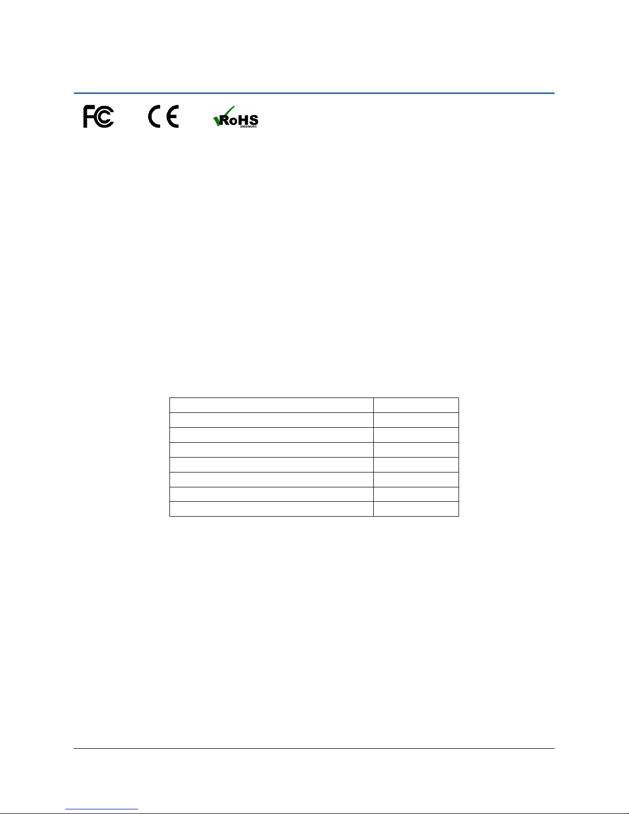
Table 1: System Specifications
Supply Voltage (rated)
12VDC
Supply Current (rated)
5A
Hydraulic Pressure (maximum)
3300 psi
Baud Rate 250 kbps
Clock Frequency (maximum)
96 MHz
Solenoid Valve PWM Frequency
300 Hz
Ultrasonic Sensor Transmit Frequency
50 kHz
Operating Temperature Range
0°C to 80°C
3
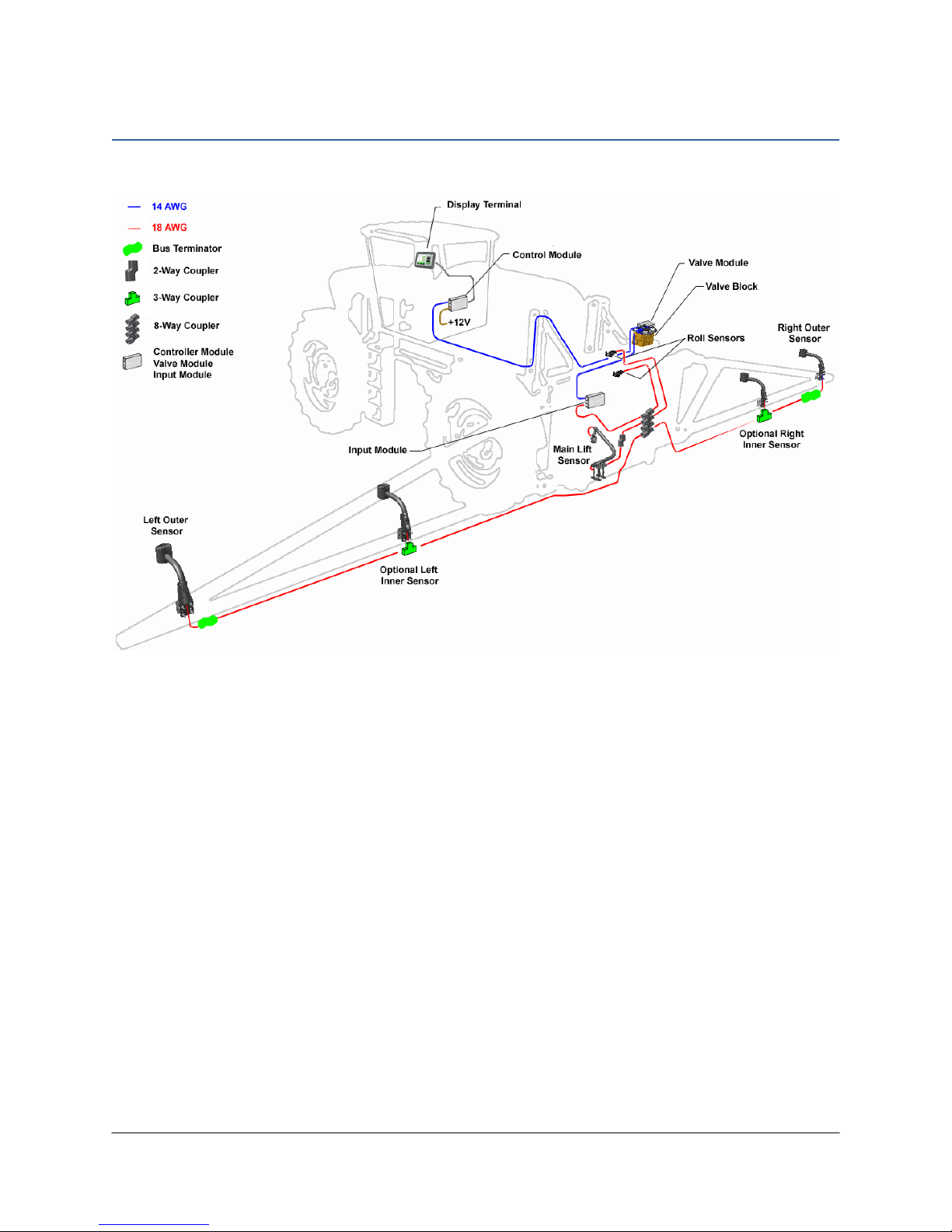
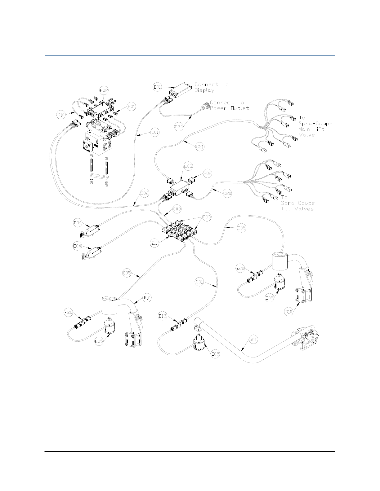
3General UC5 System Layout
Figure 1 illustrates the general layout of the UC5 system components:
Figure 1: General UC5 System Layout
4
4Kit Parts
4.1 Kit Overview
Figure 2: SC02 System Parts
5
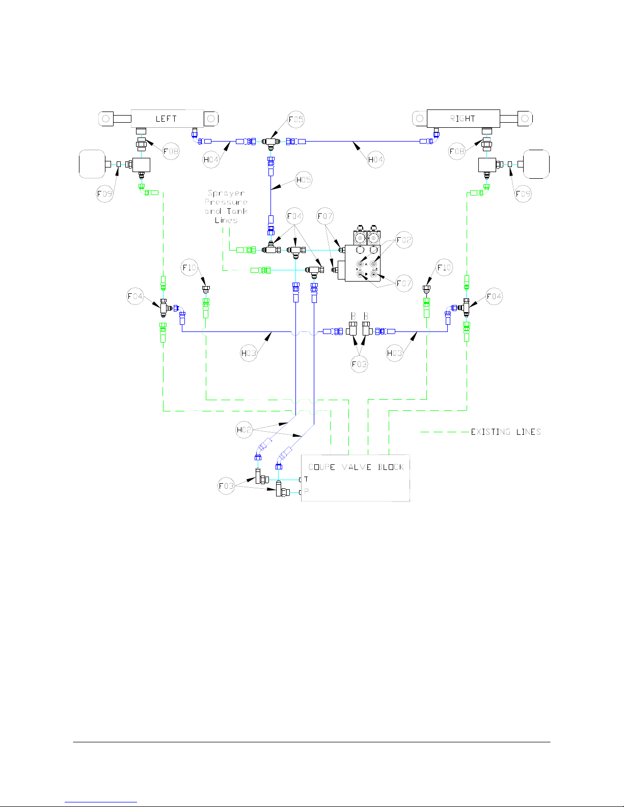
4.2 Hydraulic Plumbing
Figure 3: SC02 Hydraulic Plumbing

6
4.3 List of Parts
Item Part Number Name Quantity
B05 44706-01 KIT CABLE TIE BLACK 10 PCS 21 IN 150 PCS 7.5 IN 1
B10 44728 MOUNTING BRACKET COMPLETE UC4 BREAKAWAY EXTENDED 2
B11 44743 MOUNTING BRACKET MAIN LIFT SENSOR UC4 PLUS 1
B12 104557 GROMMET 7/8 ID X 1/4 GROOVE WIDTH X 1-1/4 GROOVE DIAMETER 1
C01 43220-01 CABLE UC5 NETWORK 14 AWG 1M 2
C02 43220-10 CABLE UC5 NETWORK 14 AWG 10M 1
C03 43220-03 CABLE UC5 NETWORK 14 AWG 3M 1
C05 43210-20 CABLE UC5 NETWORK 18 AWG 20M 2
C10 43230-04 CABLE UC5 VALVE 2PIN DT TO 2PIN DT 4
C20 43240-01 CABLE UC5 INTERFACE TILT DT 1
C21 43240-07 CABLE UC5 INTERFACE MAIN DT (WITH AUX 1 & 2) 1
C30* 43250-04 CABLE UC5 BATTERY AMP FUSED - 5A 1
E01 43710 UC5 CONTROLLER MODULE 1
E02 43720 UC5 VALVE MODULE 1
E03 43732 UC5 INPUT MODULE PASS THRU 1
E04 43741 UC5 ROLL SENSOR VER. 2 2
E05 43750 UC5 ULTRASONIC SENSOR 3
E11 43765 UC5 NETWORK COUPLER 8-WAY 1
E12 43764 UC5 NETWORK COUPLER 2-WAY 1
E20 43764T UC5 NETWORK COUPLER 2-WAY WITH TERMINATOR 2
H02 44863-13 HOSE ASSEMBLY 122R2-06 32 IN L 6FJX 6FJX45 2
H03 44863-06 HOSE ASSEMBLY 122R2-06 40 IN L 6FJX 6FJX90 2
H04 44862-17 HOSE ASSEMBLY 122R2-04 68 IN L 6FJX 6FJX 2
H05 44862-07 HOSE ASSEMBLY 122R2-04 18 IN L 6FJX 6FJX 1
H20 44865-53 HYDRAULICS FITTING KIT - SC2 1
M02 UC5-BC-SC02-INST MANUAL INSTALLATION UC5 SPRA-COUPE (7X60 SERIES 2008+) 1
M06 45015 ANTI-SEIZE LUBRICANT KIT 1
P01 106034 UC5 NETWORK 2 PIN PLUG 4
P02 106602 UC5 NETWORK 12 PIN PLUG (A-KEY) 1
P03 105882 UC5 NETWORK 6 PIN PLUG 2
V01 44963D VALVE BLOCK ASSEMBLY 2 STATION CC/LS PROP DT 4 BOLT 1
* Systems purchased prior to early 2014 may not have a fused power cable.
7
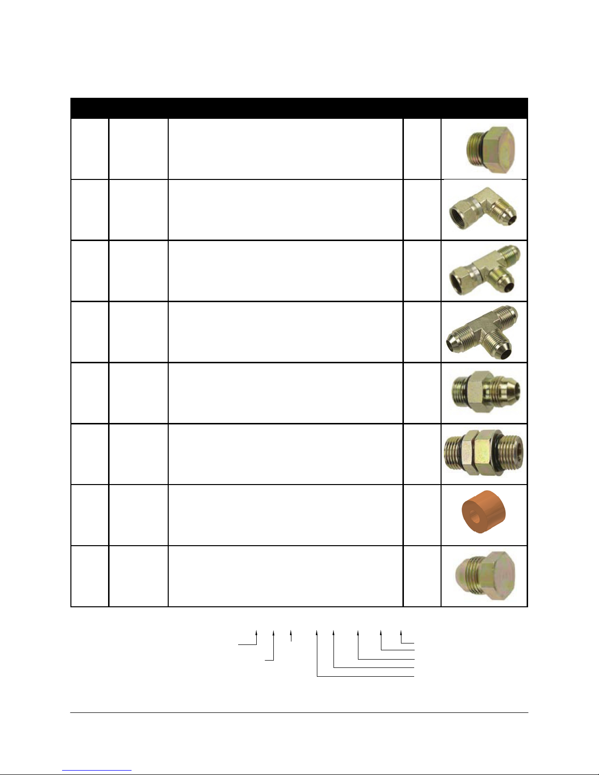
4.4 Hydraulic Fitting Kit Details (P/N: 44865-53)
Item Part Number Name Quantity
Picture
F02 104369 PLUG - 6MBP 2
F03 103345 ELBOW ADAPTER - 6MJ 6FJX90 4
F04 103839 TEE ADAPTER - 6FJXR 6MJT 5
F05 103195 TEE ADAPTER - 6MJT 1
F07 103312 MALE ADAPTER - 6MB 6MJ 4
F08 501308 MALE ADAPTER - 12MB 12MB 2
F09 105016 TWO WAY ORIFICE INSERT 3/64" 2
F10 103779 PLUG - 6MJP 2
6 M B - 6 M OR X 90
SIZE IN
1/16TH'S
GENDER: MALE
OR FEMALE
90° ANGLE
SWIVEL
TYPE
GENDER
SIZE
TYPE:
B - ORB
J - JIC
OR - FLAT
FACE
P - PIPE
Fitting Name
Example:
8
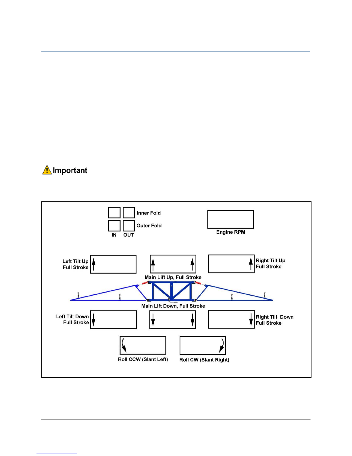
5Pre-Install Checklist
The pre-install checklist is necessary to check the existing sprayer functionality before the
installation.
1. Unfold the sprayer over a flat, unobstructed area (i.e. no power lines…etc.).
2. Ensure all boom-fold operations are functional (place a check mark in boxes below).
3. Bring engine to field-operational RPM and record below.
4. Record the time (seconds) it takes for a full stroke for all boom functions. To ensure
repeatable measurements, take the average of 3 trials.
5. Not all sprayers will have the functions listed below in Figure 4.
Ensure the boom has sufficient travel so it does not contact the ground during
these tests.
Figure 4: Pre-Install Boom Speeds
9
6Ultrasonic Sensor Installation
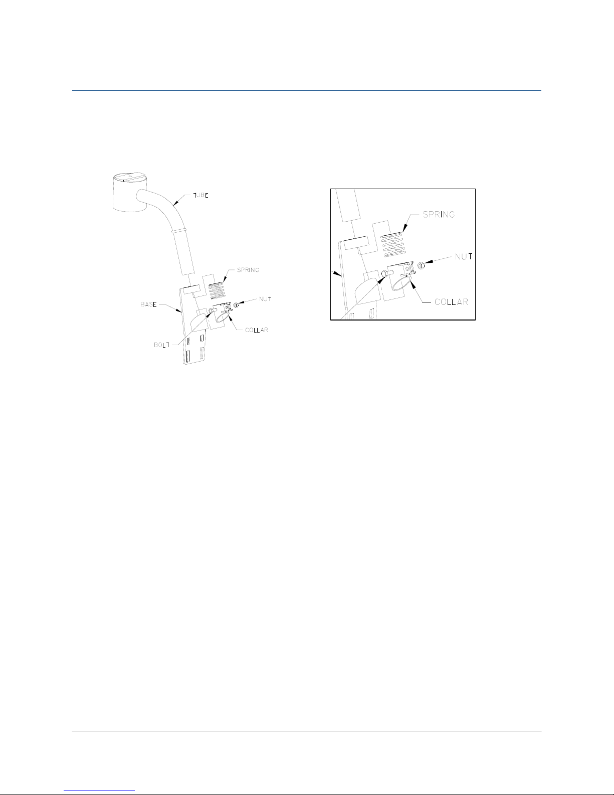
6.1 Bracket Assembly
Assemble the breakaway sensor bracket as illustrated in Figure 5, following the instructions
below.
Figure 5: Breakaway Bracket Assembly
1. Compress the spring and insert it together with the collar into the base.
2. Slide the tube through the assembled part.
3. Using the bolt and nut, tighten the collar to the tube with the sensor tube centered.
4. Apply a small amount of grease to the rotating surfaces of the bracket.
10
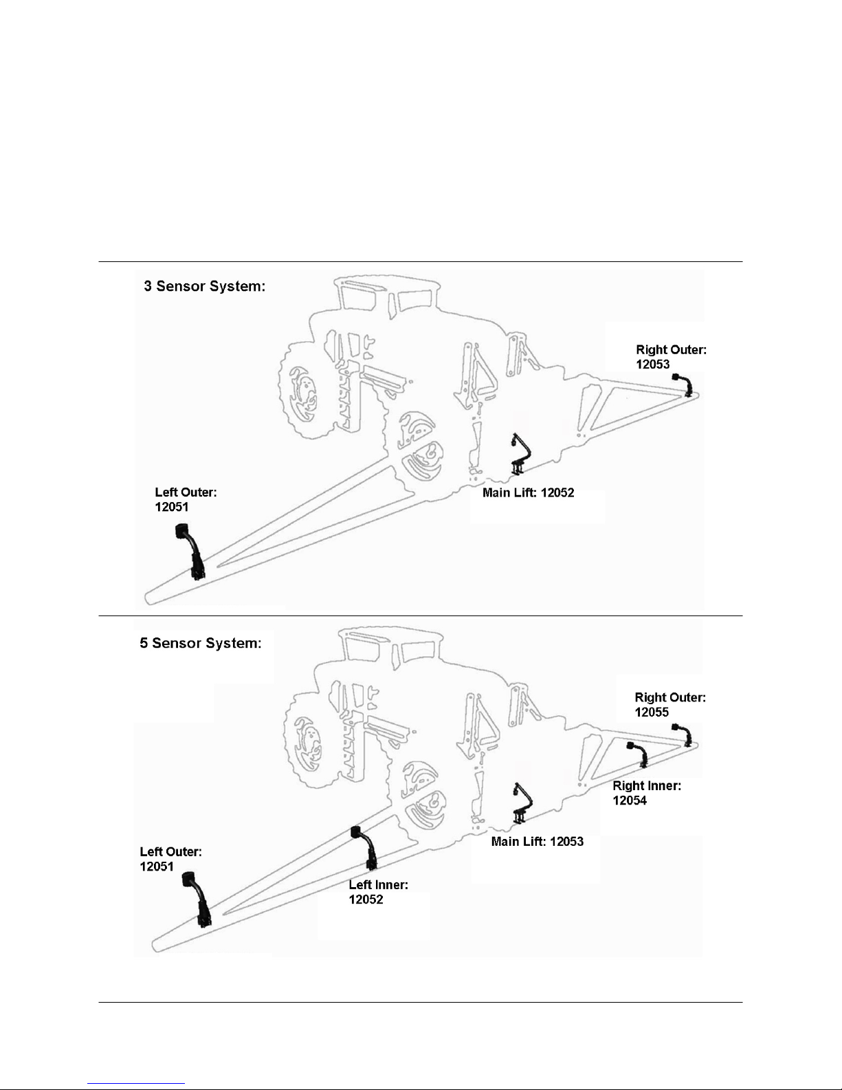
6.2 Ultrasonic Sensor Serial Number Arrangement
When installing the UC5 sensors, start with the smallest serial number on the left-hand side,
and proceed to the largest serial number on the right hand side. Each UC5 sensor has a serial
number stamped on the sensor housing.
Apply a light coating of the supplied Permatex Anti-seize grease (M06) to all
threaded parts upon installation.
Figure 6: Sensor Serial Number Arrangement

11
6.3 Ultrasonic Sensor Mounting Guidelines
The following guidelines will ensure optimal sensor performance and prevent sensor
measurement error. These rules should be followed for both the wing sensors and the main
lift (middle) sensor.
1. In its lowest position, the sensor must be 9 inches (23 cm) or more from the ground (A).
2. The centerline of the acoustic cone should be approximately vertical at normal operating
heights (A).
3. The bottom of the sensor must be at least 9 inches in front of the spray nozzles and boom
structure (B). (This does not apply for the main lift sensor)
4. The bottom of the sensor must be at least 9 inches above the spray nozzles (C).
5. Ensure there are no other obstructions with a 12 inch (23 cm) diameter circle projected
directly below the sensor (D).
Figure 7: Sensor Mounting Guidelines
12
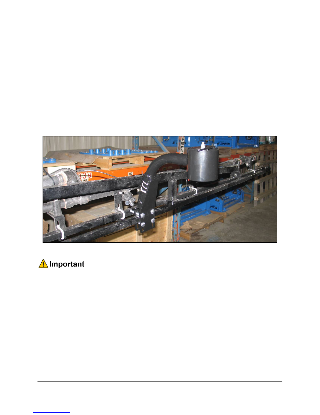
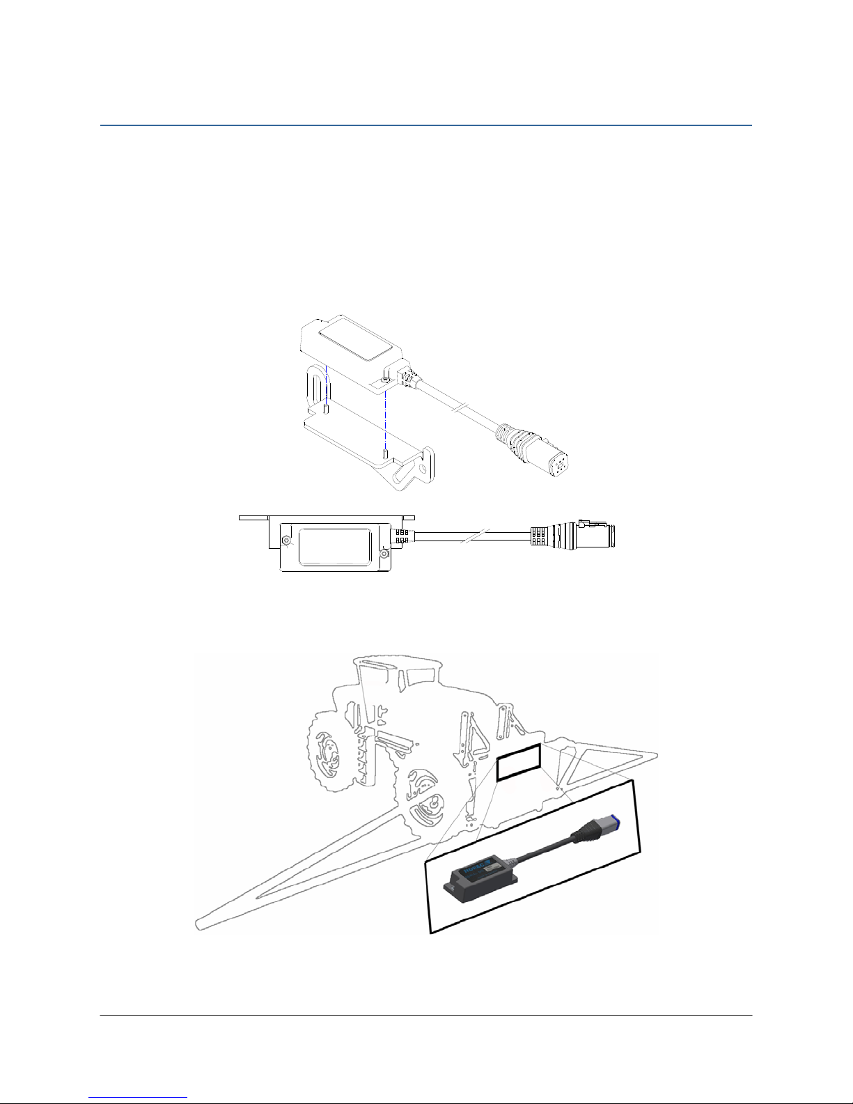
6.4 Wing Sensor Installation
1. The sensor bracket should be oriented forward (ahead of the boom).
2. Typically the best mounting location for the wing sensor brackets will be near the end of
the boom tips, approximately two feet (60cm) from the end.
3. Depending on the boom design, some breakaway sections will lift upwards as they break
back. If the sensor is mounted to this portion of the boom, the system will force the boom
downwards towards the ground as the boom folds backwards.
4. Mount the NORAC UC5 ultrasonic sensor into the sensor bracket and run the sensor
cable through the sensor tube.
Figure 8: Sensor Mounted on Spra-Coupe Boom
A problem can arise if a sensor is not mounted correctly. It is possible for the
sensor to read off of the boom instead of the ground. This may only become
apparent once the control system is switched from soil to crop mode.
Also be careful that the sensor bracket does not collide with any other part of the
boom when the boom is folded to transport position. If possible, mount the sensor
brackets while the booms are folded to ensure they will not cause interference.
13
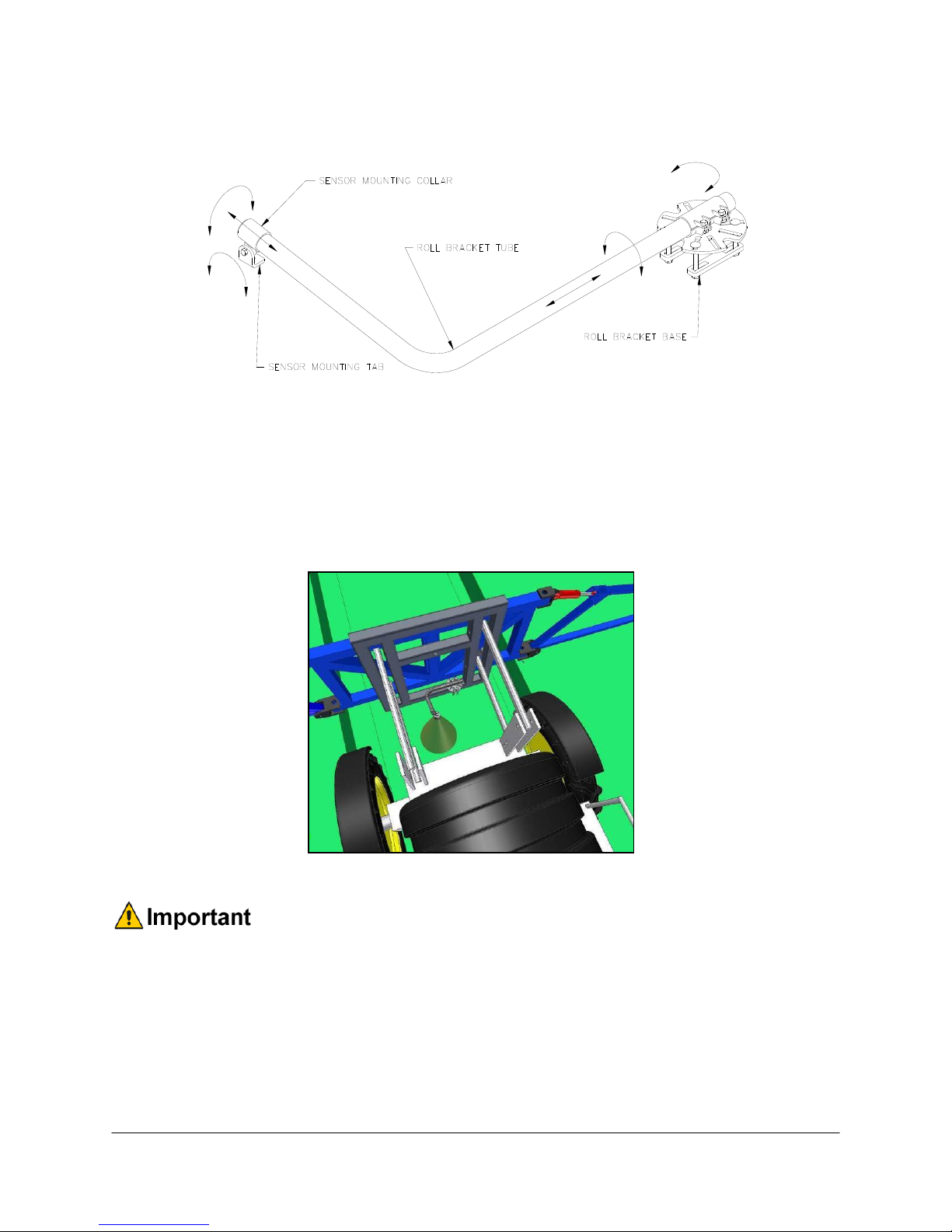
6.5 Main Lift Sensor Installation
Figure 9: Main Lift Bracket Assembly
1. There are a variety of ways to mount the main lift bracket on most sprayers. The bracket
should position the sensor approximately in the center of the sprayer, forward of the
boom. An example of this mounting is illustrated in Figure 10.
2. Mount the ultrasonic sensor to the main lift bracket. Run the sensor cable down the center
of the main lift bracket tube.
Figure 10: Example Mounting of the Main Lift Bracket
Avoid mounting the main lift sensor over or near a wheel-track. Measurements
from the wheel-track do not provide an accurate crop height and will cause
measurement and control error.
Ensure the bracket does not collide with any other part of the sprayer throughout
the full range of main lift motion.
14
7Roll Sensor Installation
7.1 Bracket Assembly
1. Securely mount the roll sensors to the included roll sensor brackets using the #6 machine
screws.
2. The orientation of the mounted roll sensor to the roll sensor bracket will depend on the
bracket mounting. The roll sensor CANbus connector must be pointing towards the right
side of the sprayer.
Figure 11: Mounting Roll Sensor to Bracket
Figure 12: Roll Sensor Orientation - Connector Facing Right Wing
15
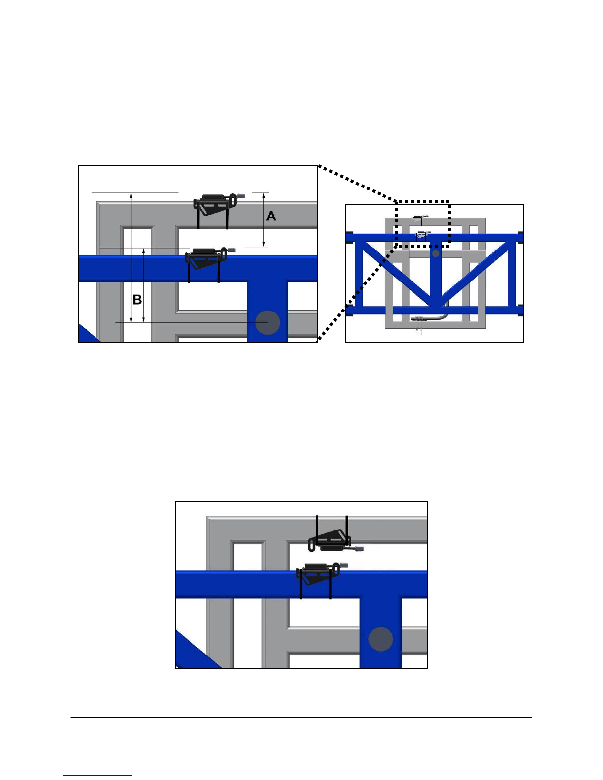
7.2 Roll Sensor Mounting Guidelines: Center Pivot Booms
1. When mounting the roll sensors, mount one to the boom frame and one to the chassis
(non-pivoting portion of the sprayer). For optimal performance, minimize the distance
between the roll sensors (A) and minimize the height from each roll sensor to the pivot
point (B).
Figure 13: Roll Sensor Mounting on a Center Pivot Suspended Boom
2. Ensure the roll sensors are relatively level when the sprayer boom and chassis are level.
3. Both roll sensor cables should be pointing towards the right hand wing of the sprayer.
4. Ensure both roll sensors are mounted adequately and that the cables provide enough slack
to allow sufficient boom roll.
5. The chassis roll sensor can also be mounted inverted to minimize the distance between the
roll sensors (Figure 14).
Figure 14: Inverted Chassis Roll Sensor Mounting on a Center Pivot Suspended Boom
16
8Module Installation
An optional module mounting bracket kit is available for purchase from NORAC. The
mounting brackets are compatible with control modules and input modules. One kit is needed
per module.
Item Part Number Name Quantity
B20 43708 UC5 MOUNTING BRACKET KIT (CONTROL AND INPUT MODULES) 1
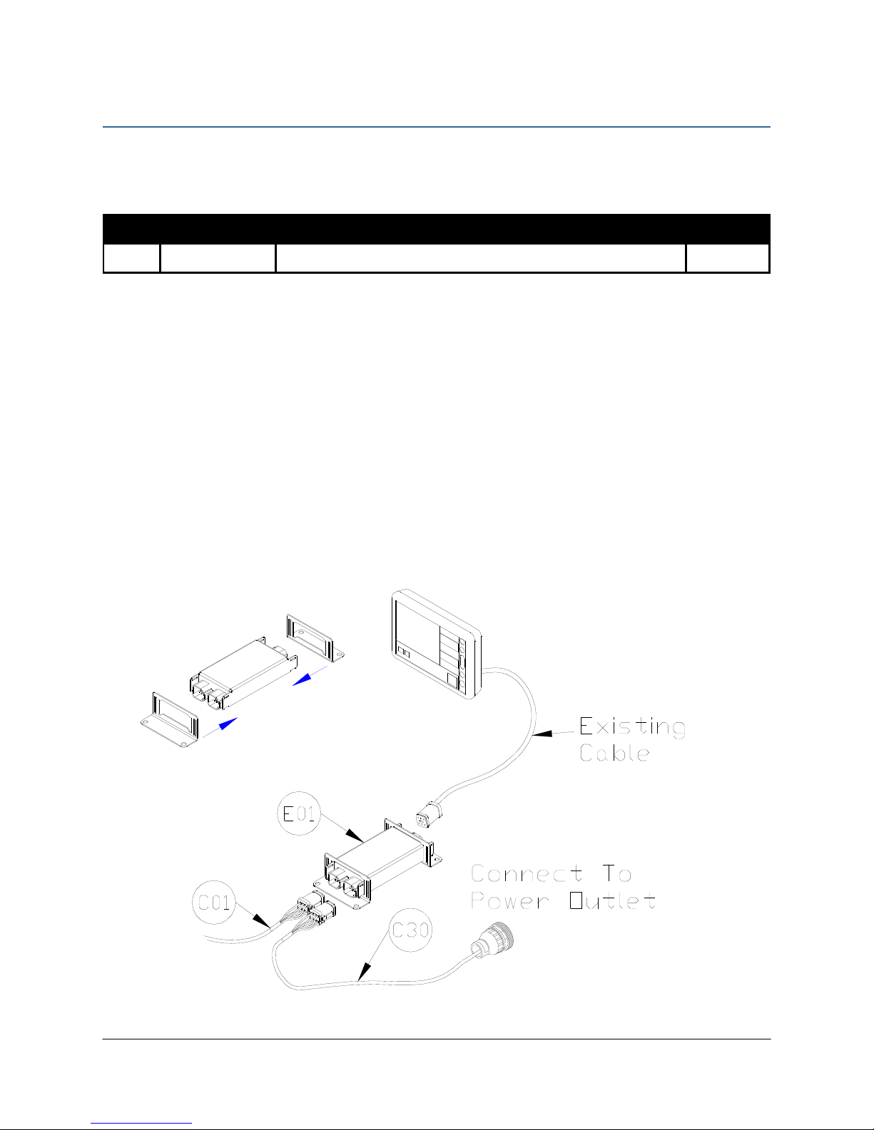
8.1 Control Module
1. Refer to Figure 1 and Figure 15.
2. Securely mount the control module (E01) inside the sprayer cab, using screws, cable ties or
optional brackets.
3. Connect the display terminal to the control module using the display cable. This cable must
be connected to the end of the control module with only one Deutsch connector.
4. Connect the power cable (C30) to one of the two CANbus connectors on the control
module. Connect the other end of the power cable to an appropriate power source.
5. Route cable C01 from the other CANbus connector towards the rear of the sprayer.
Figure 15: Control Module Mounting
17
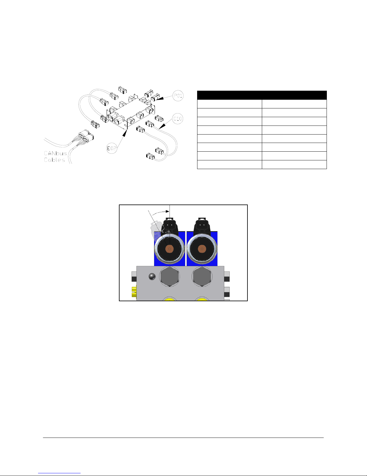
8.2 Valve Module
1. Install the valve module (E02) to the top of the NORAC valve block. Orient the 6-pin
Deutsch (CANbus) connectors towards the “P” and “T” ports.
Figure 16: Valve Module
2. Verify the valve coil connectors are oriented vertically (Figure 17).
Figure 17: Align Coils
3. Place the valve module between the valve coils. Slide a valve mounting bracket over the
connectors of the valve module and the valve coil connectors. This may require flexing the
plastic bracket slightly (Figure 18).
4. Ensure the bracket is pushed over the connectors far enough to allow the clips to engage
behind the valve connectors.
Output Numbe
r
Normal Function
1
Left Up
2
Left Down
3
Right Up
4
Right Down
5
Option 1
6
Option 2
7
Option 3
8
Option 4
Other manuals for UC5 Topcon X30
55
Table of contents
Other Norac Farm Equipment manuals

Norac
Norac UC4.5 User manual

Norac
Norac UC4 Total Control User manual

Norac
Norac UC4+ User manual

Norac
Norac UC5 Sx275 User manual

Norac
Norac UC5 Topcon X30 User manual

Norac
Norac UC4+ User manual

Norac
Norac UC5 Topcon X30 User manual

Norac
Norac UC4+ User manual

Norac
Norac UC4.5 User manual

Norac
Norac UCB Sx275 User manual


