Norac UC4 Total Control User manual

UC
4
Total Control
Automatic Boom Height
System
Rogator 1254, 1054, 854 (97+)
Installation Manual
Canada
NORAC Systems International Inc.
CALL TOLL FREE: 1-800-667-3921
(306) 664-6711
SHIPPING ADDRESS:
3702 Kinnear Place
Saskatoon, SK
S7P 0A6
United States
NORAC, Inc.
CALL TOLL FREE: 1-866-306-6722
(763) 786-3080
SHIPPING ADDRESS:
1290 Osborne Rd. NE, Suite F
Fridley, MN
55432-2892
For other service locations please view our website:
www.norac.ca
Improving the Competitiveness of Industry and Agriculture
through Precision Measurement

Printed in Canada
Copyright 2006-07 by NORAC Systems International Inc.
Reorder P/N: UC4-BC-RG4-INST Rev E (Ag Chem Rogator 1254,1054,854)
NOTICE
NORAC Systems International Inc. reserves the right to improve products and their specifications without notice
and without the requirement to update products sold previously. Every effort has been made to ensure the accuracy
of the information contained in this manual. The technical information in this manual was reviewed at the time of
approval for publication.

TABLE OF CONTENTS
1 INTRODUCTION ......................................................................................................................2
2 GENERAL SYSTEM DESCRIPTION.......................................................................................3
3 PARTS LISTS...........................................................................................................................4
4 INSTALLATION PROCEDURE .............................................................................................10
4.1 EXISTING HYDRAULIC SYSTEM FUNCTION CHECK ................................................................. 10
4.2 BOOM SPEED TEST ............................................................................................................. 11
4.3 WING SENSOR INSTALLATION .............................................................................................. 13
4.4 MAIN ROLL SENSOR AND TARGET INSTALLATION ................................................................. 18
4.4.1 The Mounting Brackets ............................................................................................ 18
4.4.2 Mounting on the Boom ............................................................................................ 19
4.5 HYDRAULIC INSTALLATION................................................................................................... 25
4.5.1 Valve Assembly and Mounting ................................................................................. 25
4.5.2 Hydraulic Plumbing .................................................................................................. 29
4.6 ELECTRICAL INSTALLATION ................................................................................................. 31
4.7 COMPLETING THE INSTALLATION.......................................................................................... 37
5 ELECTRICAL REFERENCE – CABLE DRAWINGS ............................................................38
5.1 ITEM C1: 44662B –SENSOR TRUNK CABLE ........................................................................ 38
5.2 ITEM C2: 44668 –SENSOR BRANCH CABLE ........................................................................ 38
5.3 ITEM C3: 44656 –VALVE CABLE (VARIABLE RATE) ............................................................ 39
5.4 ITEM C4: 44651 –VALVE EXTENSION CABLE....................................................................... 39
5.5 ITEM C10: 44650-39 –POWER CABLE GENERIC SELF-PROPLELLED .................................... 40
5.6 ITEM C11: 44651-03 –EXTENSION CABLE VALVE GENERIC................................................. 41
5.7 ITEM C12: 44658-32 –INTERFACE CABLE ........................................................................... 42
5.8 ITEM C14: 44658-28 –INTERFACE CABLE POWER PIGTAIL .................................................. 43
5.9 ITEM C15B 44658-41 –INTERFACE CABLE HAND CONTROL RG4........................................ 44
5.10 ITEM C16: 44658-33 –INTERFACE CABLE BYPASS ............................................................ 44

2
1 INTRODUCTION
Congratulations on your purchase of the NORAC UC4 automated sprayer boom
height control system. This system is manufactured with top quality components
and is engineered using the latest technology to provide operating features and
reliability unmatched for years to come.
When properly used the system can provide protection from sprayer boom damage,
improve sprayer efficiency, and ensure chemicals are applied correctly.
Please take the time to read this manual completely before attempting to install the
system. A thorough understanding of this manual will ensure that you receive the
maximum benefit from the system.
YOUR INPUT CAN HELP MAKE US BETTER! If you find issues or have
suggestions regarding the parts list or the installation procedure, please
don’t hesitate to contact us via the information given below:
Phone: 1-800-667-3921 in Canada (Toll Free)
1-866-306-6722 in the United States (Toll Free)
1-306-664-6711 all other regions
E-mail: service@norac.ca
Website: www.norac.ca

3
2 GENERAL SYSTEM DESCRIPTION
Figure 1 depicts the general system layout of the UC4 Sprayer Boom Control
system.
Figure 1 – System Components and General Location
NOTICE:
Every effort has been made to ensure the accuracy of the information contained in
this manual. All parts supplied are selected to fit the sprayer and supply the
customer with a complete installation. However, NORAC cannot guarantee all
parts fit as intended due to the variations of the sprayer by the manufacturer.
Please read this manual in its entirety before attempting installation.
ATTENTION:
When installing the UC4 system please be aware that at a point in the installation
your sprayer booms will be inoperative until the installation is complete. Any
installation procedure requiring boom movement will need to be done
first. Once the hydraulics have been disconnected, you must complete the electrical
installation before the booms become operative.
4
3 PARTS LISTS
The parts that come with your UC4 Sprayer Boom System are listed in Table 1. In
this document, the item number shown on the left side of this table references each
part.
Please ensure that all parts in your kit are present before proceeding with
your installation.
Table 1 – Rogator 854, 1054, 1254 BC Kit Parts
Item Part Number Description Pcs
Len
UC4-BC-RG4 KIT UC4 BOOM CONTROL ROGATOR
854,1054,1254
1
EA
* BRACKET PARTS *
B10 44704 MOUNTING BRACKET UC4-BC VALVE 1 EA
B11 44740 MOUNTING BRACKET ROLL SENSOR UC4 1 EA
B12 44741 MOUNTING BRACKET ROLL SENSOR TARGET UC4 1 EA
B13* 44728 MOUNTING BRACKET COMPLETE UC4 BREAKAWAY
EXTENDED
2 EA
B16 44701 PLATE ACCESS ROGATOR 854 1 EA
B17 44702 PLATE ACCESS ROGATOR 854 (POWER) 1 EA
B18 44703 PLATE ACCESS ROGATOR 854 (TRUNK) 1 EA
B19 44724 BRACKET BREAKAWAY SPACER 2IN WITH BOLTS 2 EA
* CABLE PARTS *
C1 44662B-40 CABLE UC4 SENSOR TRUNK AMPF TO AMPF
BLACK STANDARD 40FEET
1 EA
C2 44668 CABLE UC4 SENSOR 1 AMP RECEPT 3 AMP PLUG
BC
1 EA
C3 44656 CABLE VALVE VARIABLE RATE 1 EA
C4 44651 CABLE VALVE EXTENSION 1 EA
C10 44650-39 POWER CABLE GENERIC SELF-PROPELLED 1 EA
C11 44651-03 CABLE EXTENSION VALVE GENERIC 1 EA
C12 44658-32 CABLE INTERFACE C12 ROGATOR
854,1054,1254
1 EA
C14 44658-28 CABLE UC4 INTERFACE C14 POWER PIGTAIL 1 EA
C15B 44658-41 CABLE UC4 INTERFACE C15B HAND CONTROL
RG4
1 EA
C16 44658-33 CABLE UC4 INTERFACE C16 RG4 BYPASS 1 EA

5
Item Part Number Description Pcs
Len
* ELECTRONIC PARTS *
E1 4461BC UC4 BOOM CONTROL PANEL 1 EA
E2 44631 UC4 ULTRASOUND SENSOR 3 EA
* HYDRAULIC PARTS *
V1** 44933
or
44933S
VALVE PACKAGE CC LS PROP 2 STATION
EXPANDABLE W/FILTER
VALVE BLOCK ASSEM UC4-BC 2-STATION CC/LS
VARIABLE RATE
1 EA
H1 103839 COUPLING HYD 6FJXR 6MJT 2 EA
H2 104632 COUPLING HYD 8FJXR 8MJT 1 EA
H3 104634 COUPLING HYD 6FJCN CAP NO 6 FEMALE JIC 2 EA
H4 100655 HYD HOSE 2 WIRE 3/8 IN 1 32 IN
104459 HYD HOSE END 6WC 6FJX90 1 EA
102897 HYD HOSE END 6WC 6FJX 1 EA
H5 100655 HYD HOSE 2 WIRE 3/8 IN 1 32 IN
104459 HYD HOSE END 6WC 6FJX90 1 EA
103775 HYD HOSE END 6WC 8FJX 1 EA
H6 104517 COUPLING HYD 12FJ 6MJ 2 EA
H7 102897 HYD HOSE END 6WC 6FJX 2 EA
100655 HYD HOSE 2 WIRE 3/8 IN 1 135 IN
H8 102897 HYD HOSE END 6WC 6FJX 2 EA
100655 HYD HOSE 2 WIRE 3/8 IN 1 175 IN
H10 44934 COUPLING HYD 12MJ 6FB PORT 2 EA
H11 44926 ORIFICE INSERT .047 FIXED 2 EA
H12 103312 COUPLING HYD 6MB 6MJ 2 EA
H13 100656 HYD HOSE 1/4 IN 5000 PSI 2 18 IN
103189 HYD HOSE END 4WC 6FJX 4 EA
H14 104189 COUPLING HYD 10MB 8MJ 1 EA
H17 104629 COUPLING HYD 12FJXR 12MJT 1 EA
H18 104628 COUPLING HYD 12FJ 8MJ 1 EA
H19 104386 COUPLING HYD 8FJ 6MJ 1 EA
H50 44928 ORIFICE INSERT .047 IN ONE WAY 2 EA
H51 103312 COUPLING HYD 6MB 6MJ 4 EA

6
Item Part Number Description Pcs
Len
H52 104369 COUPLING HYD 6MBP 2 EA
H53** 44920 SANDWICH BLOCK KIT - SINGLE ACTING 2 EA
* MISC. PARTS *
M1A 446BC-MAN-1 MANUAL UC4 BOOM CONTROL TECHNICAL LARGE
BOOKLET
1 EA
M1B 446BC-MAN-2 MANUAL UC4 BOOM CONTROL QUICK REFERENCE
SMALL BOOKLET
1 EA
M2 100084 TIE CABLE 21 IN BLACK 10 EA
M3 100091 TIE CABLE 7.5 IN BLACK 150 EA
M4 104409 FOAM DISC 45 PPI CONDUCTIV 1/2 X 2-5/8
DIA
6 EA
M5 105435 CHAIN 1/2 IN PLASTIC 3 42 IN
M6 100660 BOLT HEX NC GR5 PLTD 1/4 IN 3 EA
M7 100853 NUT HEX NC GR5 PLTD ¼ IN 3 EA
M10 UC4-BC-RG4-
INST
MANUAL INSTALLATION UC4 ROGATOR 1254,
1054, 854 (‘97+)
1 EA
M11 100645 BOLT HEX NC GR5 PLTD 3/8X4 2 EA
M12 100947 WASHER LOCK SPRING PLTD 3/8 IN 2 EA
M13 100823 SCREW TAPPING NO 6 X 3/8 TRUSS 6 EA
M14 44942 TUBING PLASTIC CLEAR PETG 2.75X.28 1 16 IN
* In a kit shipped prior to February 1, 2007, the part number for Item B13 is 44722.
** If the part number for Item V1 (NORAC valve block) is 44933S, Items H53 are not
included in the kit. The #44933S valve block has solenoid valves whose engraved part
number is “105723”. Please see Section 4.5.1 for further details.
ATTENTION:
Your Rogator sprayer may require different cabling depending on the
connectors used near the valve block. Please refer to Table 2 and Table 4
for ordering alternate cabling from NORAC.

7
Table 2 – Alternate Interface Cabling Available from NORAC
Item Replaced Description Connector Type Norac Part #
C12 Interface Cable Weatherpack 44658-21
C12 Interface Cable Metripack 280 44658-32
C12 Interface Cable Deutsch DT 44658-24
NOTE: If your sprayer uses a bypass/jam valve, choose from the
Bypass/Jam Cabling options in Table 3 and Table 4 for ordering
bypass cabling from NORAC.
Table 3 – Bypass/Jam Cabling Available from NORAC
Item No. Description Connector Type Norac Part #
C16 Bypass Cable Weatherpack 44658-34
C16 Bypass Cable Metripack 280 44658-33
C16 Bypass Cable Deutsch DT 44658-27
Table 4 – Illustrations of Connector Types
Weatherpack
Metripack 280
Deutsch DT

8
The parts that come with your UC4 System are listed in the above table and shown
in their general installation configuration.
Figure 2 – UC4 Boom Control Components
9
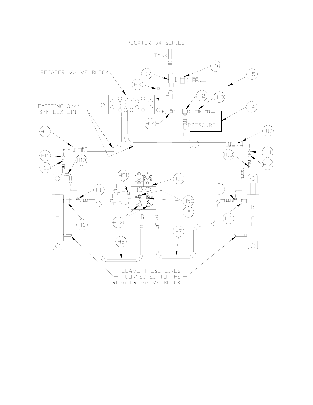
Figure 3 - Hydraulic Components
NOTE: If the part number of Item V1 is 44933S, Items H53 are not included in the kit.
10
4 INSTALLATION PROCEDURE
Before installing the NORAC UC4 Boom Control System to your sprayer, it is
necessary to check that all functions of the existing hydraulic system are working
properly.
Furthermore, it is informative to determine how quickly your sprayer booms and
main (center) section are able to change their position without the UC4 System
installed. Doing so may illustrate the design strengths and constraints of your
sprayer’s mechanical and hydraulic configuration.
This information may also prove valuable when troubleshooting the installation,
and if you need to contact NORAC for installation support. For example, NORAC
support staff may use this information to determine if there are unwanted orifices
(or backwards orifices) remaining in the hydraulic system when the UC4 System is
installed.
Drive your sprayer onto a flat piece of land, without any obstructions in the way of
boom movement (e.g. power lines). Try to gain the best view of the booms and
involved cylinders as you can. This may be best done with two people: one in
the cab, and one outside. Perform the following Function Check and Boom Speed
Test.
4.1 Existing Hydraulic System Function Check
Check all functions of the existing hydraulic system of your sprayer on Table 5.
There may be more functions in the existing hydraulic system. Please refer to the
sprayer’s operation manual and check additional functions, if necessary.
Table 5 – Hydraulic System Function Check Sheet
HYDRAULIC SYSTEM FUNCTION
INNER OUTER TIP* FIELD
OPERATION
FOLD UNFOLD FOLD UNFOLD FOLD UNFOLD UP DOWN
LEFT BOOM
RIGHT BOOM
MAIN BOOM N/A N/A N/A N/A N/A N/A
ROLL* N/A N/A N/A N/A N/A N/A
*Some sprayers may not have this function/section.

11
4.2 Boom Speed Test
IMPORTANT:
Let the sprayer run for several minutes to heat up the hydraulic oil.
Raise/lower the left and right booms, main and hydraulic roll sections
several times to help get the system (hydraulic oil, valve solenoids)
warmed up. This will simulate field conditions and makes QUITE a
difference in some cases. Grease all moving parts for consistent results.
1. Lower each boom and main section as close to the ground as possible.
2. Set your sprayer at field working RPM on the throttle and mark this value in
Table 6.
NOTE: You will need a stopwatch or a watch that displays “seconds” for
the next step.
3. Individually raise the LEFT boom from its extreme LOW position to the very
TOP of its travel. Note the length of time it takes for this and record this in
Table 6,“Trial #1” for “Left UP”.
4. Individually lower the LEFT boom from its extreme HIGH position to the
BOTTOM of its travel. Note the length of time it takes for this and record this
in Table 6,Trial #1, for “Left DOWN”.
NOTE: You will need to be careful when lowering the booms at full speed
to the bottom of their travel so that they don’t hit the ground. You
may want to mark positions on the cylinder pistons at which to
stop the test while using another person as a spotter. Raising your
main section will give you more working height to do this test.
Please use common sense to avoid damage!
5. Similarly, record two more time trials (Trial #2 & #3) for the LEFT boom and
record in Table 6.
6. Repeat Steps 3 through 5 for the RIGHT boom and the MAIN section.
7. Repeat a similar procedure for the hydraulic (active) roll feature (if your sprayer
supports this) for the clockwise (CW) and counter-clockwise (CCW) rotations.
8. Average the times of the three trials recorded for each boom movement function
(e.g. LEFT, RIGHT, etc.) and record this calculation in the appropriate “Average
Time” slot in Table 6.
9. These “Average Times” now represent how quickly your system can react to

12
manual control of boom functions. In Section 4.7 Completing the
Installation, this procedure is repeated with the UC4 System installed for
comparison and troubleshooting purposes.
Table 6 – Boom Test Record (WITHOUT UC4 System)
Working RPM:
Section: Trial #1
[Seconds]
Trial #2
[Seconds]
Trial #3
[Seconds]
Average
Time
[Seconds]
LeftUP
Left DOWN
RightUP
Right Down
MainUP
Main DOWN
Roll CW
Roll CCW
Table 7 – Boom Test Record (WITH UC4 System)
Working RPM (Set this the same as in Table 6):
Section: Trial #1
[Seconds]
Trial #2
[Seconds]
Trial #3
[Seconds]
Average
Time
[Seconds]
LeftUP
Left DOWN
RightUP
Right DOWN
MainUP
Main DOWN
Roll CW
Roll CCW

13
4.3 Wing Sensor Installation
1. Assemble the Breakaway Sensor Mounting Brackets as show in Figure 4 and
Figure 5.
Figure 4 – Breakaway Sensor Bracket Exploded View
Figure 5 – Breakaway Sensor Mounting Bracket Assembly
To assemble the breakaway sensor bracket:
a) Assemble the bolt and nut into the collar of the bracket.
b) Grease the bottom edge of the collar and the angled tube of the base.
c) Place the collar onto the angled tube of the mounting base.
d) Compress and install the spring between the collar and the upper ring of the
base.
14
e) Install the tube as shown and, for now, lightly tighten collar around the tube
you will need to aim the sensor bracket later.
2. In order to reduce the chance of problems, inspect the booms in their folded
position. Mark the locations where the sensor brackets can be mounted without
contacting the sprayer. Then the booms can be unfolded and the sensors
mounted without having any mechanical interference.
NOTE: If possible, mount the sensor brackets while the booms are in
their folded position to ensure that the sensor and bracket will
not interfere with anything when the boom is folded for
transport.
NOTE: Please be aware of the maximum length of the sensor branch
cable (Item C2) for each branch. Note that the sensors can not
be mounted outside of this range on each boom. It might be
wise to route the branch cable at this time to ensure that the
cable reaches to the sensors. (Please refer to Section 4.6
Electrical Installation.)
IMPORTANT:
Provide enough slack in the sensor branch cable to account for
the movement of the main section, parallel lift, and FOLDING
boom movement.
3. Mount one NORAC UC4 ultrasonic sensor (Item E2) near the tip of each boom
with the brackets provided (Item B13). Use the 8-mm nuts and lock washers
provided with the sensor, to attach the sensor to the bracket. The sensors
should be oriented forward (ahead) of the boom.
General mounting rules for UC4 ultrasonic wing sensors:
•When the boom is in its lowest position, the sensor mouth must be 9 inches or
more from the ground.
•The bottom of the sensor must be at least 9 inches in front of the spray
nozzles.
•The bottom of the sensor must be at least 9 inches above the spray nozzles.
•The sensor should be approximately vertical at normal operating heights.
•Ensure that there are no obstructions within a 12-inch diameter circle
projected directly below the center of the sensor.
Improved boom tip protection and control may be obtained by mounting the
sensor as close to the end of the boom as possible. However, if the sensors are
15
mounted to the breakaway portion of the boom, the operator must be
aware that, due to boom geometry, a breakaway action may cause the
UC4 Control Panel to force the boom dangerously close to the ground.
For this reason, you may want to avoid mounting on a breakaway
section.
Please refer to the UC4 system warranty at the end of the UC4 Sprayer Boom
Control Operator’s Manual (Item M1) for implications.
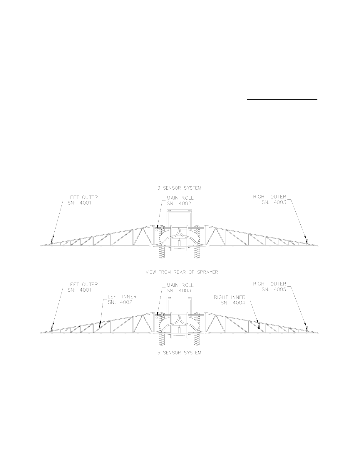
NOTE: When installing the UC4 sensors (Item E2), start with the
smallest serial number on the left hand side proceeding to the
largest serial number on the right hand side (Figure 6). This will
allow for a more intuitive setup when tuning the system. This
arrangement is also REQUIRED when using the “QUICK
SETUP” feature available via the UC4 Control Panel software
(this feature is typically used by NORAC technical support staff).
Figure 6 – Sensor Serial Number Installation Location

16
4. The sensor mounting brackets can be installed two basic ways: with the base
behind the tube (Figure 7 and Figure 9), which is preferred, or with the base
mounting in front of the tube (Figure 8). Both mountings are acceptable.
However, the preferred mounting will be less likely to damage the bracket in the
event of a boom contacting a post or obstruction.
Figure 7 – Sensor Mounting (Preffered)
Figure 8 – Another Acceptable Mounting
FRONT
17
Figure 9 – Sensor Mounting Example
NOTE: Some sprayer booms may need the spacers (Item B19) with the
sensor mounting brackets (Figure 10).
Figure 10 – Sensor Mounting with Spacer
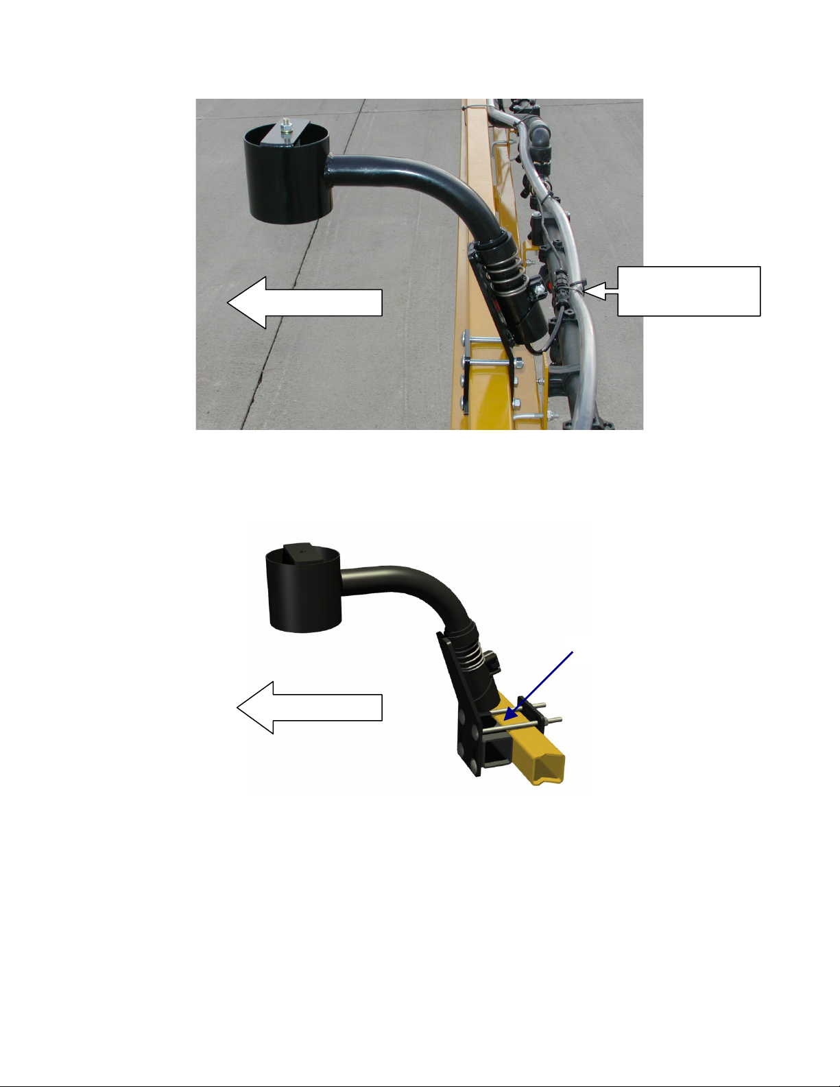
5. The sensor cable should be run down through the tube of the mounting bracket
and then behind the member the bracket is mounted onto. Cable-tie (Item M3)
the connector in place. The cable must not be allowed to hang below the boom (
Figure 8 and Figure 9).
FRONT
FRONT
SPACER
SENSOR CABLE
and CABLE-TIE

18
4.4 Main Roll Sensor and Target Installation
4.4.1 The Mounting Brackets
The brackets are designed to be very flexible and allow for a wide range of
installations.
Figure 11 – Target Bracket
The Target Bracket (Item B12) can be mounted in any direction around most sizes
of sprayer frame member and aimed using two ball and socket connections. The
dual ball connection also allows for a few inches of height adjustment while
allowing the rod to remain horizontal.
Figure 12 – Sensor Bracket
The Roll Sensor Bracket (Item B11) can be mounted in any orientation on most any
frame member. The base can be mounted horizontal or vertical and be rotated
about 20 degrees. The tube can slide in and out of the base and be rotated to give a
great deal of mounting options. The mounting collar can also be slid along the tube
and rotated. The mounting tab can rotate perpendicular to the collar giving full
range of motion allowing the sensor to point directly towards the ground no matter
the angle or direction of the tube.
Other manuals for UC4 Total Control
11
Table of contents
Other Norac Farm Equipment manuals

Norac
Norac UC4.5 User manual

Norac
Norac UC4.5 User manual

Norac
Norac UC5 Topcon X30 User manual

Norac
Norac UCB Sx275 User manual

Norac
Norac UC4+ User manual

Norac
Norac UC5 Topcon X30 User manual

Norac
Norac UC4+ User manual

Norac
Norac UC5 Sx275 User manual

Norac
Norac UC4+ User manual

Norac
Norac UC5 Topcon X30 User manual


