Norac UC4+ User manual
SPRA-COUPE 7X60 2008+
Installation Manual
Spray Height Controller
Improving the competitiveness of Industry and
Agriculture through Precision Measurement

Printed in Canada
Copyright ©2005-08 by NORAC Systems International Inc.
Reorder P/N: UC4+BC+SC2-INST Rev B (SPRA-COUPE 7X60 2008+)
NOTICE
NORAC Systems International Inc. reserves the right to improve products and their specifications without notice and without the requirement to update
products sold previously. Every effort has been made to ensure the accuracy of the information contained in this manual. The technical information in
this manual was reviewed at the time of approval for publication.

TABLE OF CONTENTS
1INTRODUCTION..................................................................................................................................................1
2GENERAL SYSTEM DESCRIPTION ..................................................................................................................2
3PARTS LISTS ......................................................................................................................................................3
4INSTALLATION PROCEDURE...........................................................................................................................7
4.1 EXISTING SYSTEM CHECK ...............................................................................................................................7
4.2 BOOM SPEED TEST........................................................................................................................................7
4.3 WING SENSOR INSTALLATION ........................................................................................................................9
4.4 MAIN LIFT SENSOR INSTALLATION................................................................................................................13
4.5 ROLL SENSOR INSTALLATION.......................................................................................................................14
4.5.1 Boom Roll Sensor Mounting 15
4.5.2 Chassis Roll Sensor Mounting 15
4.5.3 Inverted Roll Sensor Mounting 16
4.5.4 Temperature probe 17
4.6 HYDRAULIC INSTALLATION ...........................................................................................................................18
4.6.1 Valve Assembly 18
4.6.2 Valve Mounting 19
4.6.3 Hydraulic Plumbing 20
4.7 ELECTRICAL INSTALLATION..........................................................................................................................22
4.8 COMPLETING THE INSTALLATION ..................................................................................................................27
5ELECTRICAL REFERENCE – CABLE DRAWINGS........................................................................................28
5.1 ITEM C01: 44662B –SENSOR TRUNK CABLE...............................................................................................28
5.2 ITEM C02: 44668 –SENSOR BRANCH CABLE...............................................................................................28
5.3 ITEM C02B: 44664 –CABLE UC4 CAN NODE DUAL....................................................................................29
5.4 ITEM C03: 44656 –VALVE CABLE (VARIABLE RATE) ...................................................................................30
5.5 ITEM C04: 44651 –VALVE EXTENSION CABLE .............................................................................................31
5.6 ITEM C10: 44650-38 –POWER CABLE SPRA COUPE 7000 <CABLE A>........................................................32
5.7 ITEM C10: 44650-38 –POWER CABLE SPRA COUPE 7000 <CABLE B>........................................................33
5.8 ITEM C11: 44658-15 –JAM VALVE CABLE SPRA COUPE 7000.....................................................................34

1
1 INTRODUCTION
Congratulations on your purchase of the NORAC UC4+ Spray Height Controller. This system is
manufactured with top quality components and is engineered using the latest technology to provide
operating features and reliability unmatched for years to come.
When properly used the system can provide protection from sprayer boom damage, improve sprayer
efficiency, and ensure chemicals are applied correctly.
Please take the time to read this manual completely before attempting to install the system. A thorough
understanding of this manual will ensure that you receive the maximum benefit from the system.
YOUR INPUT CAN HELP MAKE US BETTER! If you find issues or have suggestions regarding
the parts list or the installation procedure, please don’t hesitate to contact us via the information
given below:
Phone: 1-800-667-3921 Canada (Toll Free)
1-866-306-6722 United States (Toll Free)
0-800-404-8389 United Kingdom (Toll Free)
1-306-664-6711 all other regions
E-mail: [email protected]
Website: www.norac.ca

2
2 GENERAL SYSTEM DESCRIPTION
Figure 1 depicts the general system layout of the UC4+ Spray Height Control system.
Figure 1 – System Components and General Location
NOTICE:
Every effort has been made to ensure the
accuracy of the information contained in this
manual. All parts supplied are selected specially
to fit the sprayer to facilitate a complete
installation. However, NORAC cannot
guarantee all parts fit as intended due to the
variations of the sprayer by the manufacturer.
Please read this manual in its entirety before
attempting installation.
ATTENTION:
When installing the UC4+ Spray Height Control
system please be aware that at a point in the
installation your sprayer booms will be
inoperative until the installation is complete.
Any installation procedure requiring boom
movement will need to be done first. Once the
hydraulics have been disconnected you must
complete the electrical installation before the
booms become operative.

3
3 PARTS LISTS
The parts that come with your UC4+ System are listed in Table 1. The item number on the left side of
this table references each part.
Please ensure that all parts in your kit are present before proceeding with your installation.
Table 1 – SPRA-COUPE Spray Height Control System Parts
Item Part Number Name Quantity
B05 44706-01 KIT CABLE TIE BLACK 10 PCS 21 IN 150 PCS 7.5 IN 1
B10 44700-06 BRACKET VALVE MOUNTING STD 1
B11 44743 MOUNTING BRACKET MAIN LIFT SENSOR UC4 PLUS 1
B13 44728 MOUNTING BRACKET COMPLETE UC4 BREAKAWAY EXTENDED 2
C01 44662B-40 CABLE UC3 SENSOR TRUNK AMPF TO AMPF BLACK STANDARD 40FEET 1
C02 44668 CABLE UC3 SENSOR BRANCH 1 AMP RECEPT 3 AMP PLUG BC 1
C02B 44664 CABLE UC4 CAN NODE DUAL 1
C03 44656D CABLE VALVE VARIABLE RATE DT 1
C04 44651 CABLE VALVE EXTENSION 1
C10 44650-38 CABLE POWER UC4 BC SPRA COUPE 7000 SERIES 1
C11 44658-15 CABLE JAM VALVE SPRA COUPE 7000 SERIES 1
E01 4461BC+ UC4 PLUS BOOM CONTROL PANEL 1
E02 44631 UC4 ULTRASOUND SENSOR 3
E03 44641 UC4 PLUS ROLL SENSOR W TEMPERATURE PROBE 1
E04 44642 UC4 PLUS ROLL SENSOR 1
H02 44863-13 HOSE ASSEMBLY 122R2-06 32 IN L 6FJX 6FJX45 2
H03 44863-06 HOSE ASSEMBLY 122R2-06 40 IN L 6FJX 6FJX90 2
H04 44862-17 HOSE ASSEMBLY 122R2-04 68 IN L 6FJX 6FJX 2
H05 44862-07 HOSE ASSEMBLY 122R2-04 18 IN L 6FJX 6FJX 1
H20 44865-53 HYDRAULICS FITTING KIT - SC2 1
M01 446BC+MAN7 OPERATOR MANUAL UC4+ SPRAY HEIGHT CONTROL 1
M10 UC4+BC+SC1-INST MANUAL INSTALLATION UC4+ SPRAY COUPE 7000 SERIES 1
M15 104557 GROMMET 7/8 ID X 1/4 GROOVE WIDTH X 1-1/4 GROOVE DIAMETER 1
V01 44933D VALVE BLOCK ASSEM UC5-BC 2-STATION CC/LS VARIABLE RATE DT 1
4
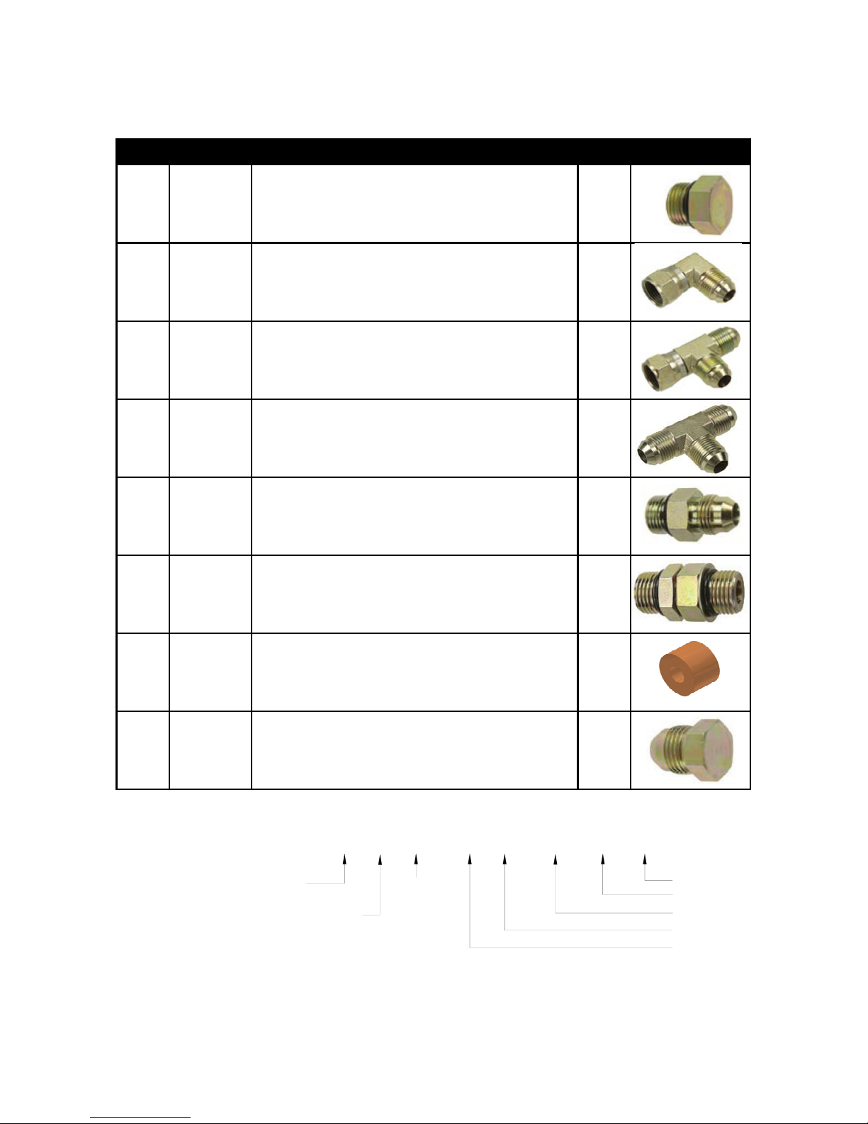
Table 2 – 44865-53 - Hydraulics Fittings Kit
Item Part Number Name Quantity Picture
F02 104369 PLUG - 6MBP 2
F03 103345 ELBOW ADAPTER - 6MJ 6FJX90 4
F04 103839 TEE ADAPTER - 6FJXR 6MJT 5
F05 103195 TEE ADAPTER - 6MJT 1
F07 103312 MALE ADAPTER - 6MB 6MJ 4
F08 501308 MALE ADAPTER - 12MB 12MB 2
F09 105016 TWO WAY ORIFICE INSERT 3/64" 2
F10 103779 PLUG - 6MJP 2
6 M B - 6 M OR X 90
SIZE IN
1/16TH'S
GENDER: MALE
OR FEMALE
90° ANGLE
SWIVEL
TYPE
GENDER
SIZE
TYPE:
B - ORB
J - JIC
OR - FLAT
FACE
P - PIPE
Fitting Name
Example:
5
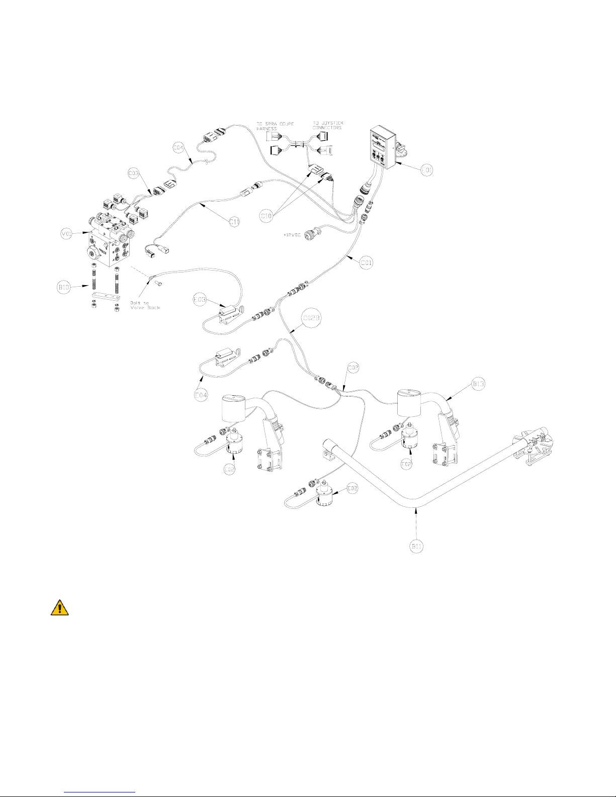
The parts that come with your UC4+ Spray Height Control system are shown below in their general
installation configuration.
Figure 2 – UC4+ Spray Height Control Components
If your valve connectors or cables appear different than shown, refer to Appendix A for more
details.

6
Figure 3 – Hydraulic Components

7
4 INSTALLATION PROCEDURE
4.1 EXISTING SYSTEM CHECK
It is necessary to check the existing system’s
functionality before installing the UC4+ Spray
Height Control system.
1. Drive your sprayer onto a flat piece of land,
with unobstructed boom movement (e.g. no
power lines).
2. Test that all boom functions operate
correctly. As you test each function check it
off in Table 3.
It is necessary to test the boom
functions in all directions
Table 3 – Hydraulic System Function Check
Sheet
BOOM
FOLD
IN
FOLD
OUT UP DOWN
LEFT
MAIN
RIGHT
ROLL* N/
A
N/
A
*Some sprayers may not have this function.
4.2 BOOM SPEED TEST
IMPORTANT:
Raise/lower all boom sections several times to
warm up the hydraulic system. Grease all
moving parts for consistent results.
1. Lower each boom and main section as close
to the ground as possible.
2. Set your sprayer at field working RPM on the
throttle and mark this value in Table 4.
You will need a stopwatch or a watch
that displays “seconds” for the next
step.
3. Raise the LEFT boom from its extreme LOW
position to the very TOP of its travel.
Record the time this takes in Table 4,“Trial
#1” for “Left UP”.
4. Lower the LEFT boom from its extreme
HIGH position to the BOTTOM of its travel.
Record this time in Table 4, Trial #1, for
“Left DOWN”.
Be careful when lowering the booms so
they don’t hit the ground.
5. Similarly, record two more time trials (Trial
#2 & #3) for the LEFT boom and record in
Table 4.
6. Repeat Steps 1through 5for the RIGHT,
MAIN and ROLL functions.
Your sprayer may not have a roll
feature.
7. Average the three trials recorded for each
boom movement and record this calculation
in the “Average Time” slot in Table 4.
8. These “Average Times” now represent how
quickly your system can react to manual
control. In Section 4.8, this procedure is
repeated with the UC4+ Spray Height
Control system installed for comparison and
troubleshooting purposes.
8
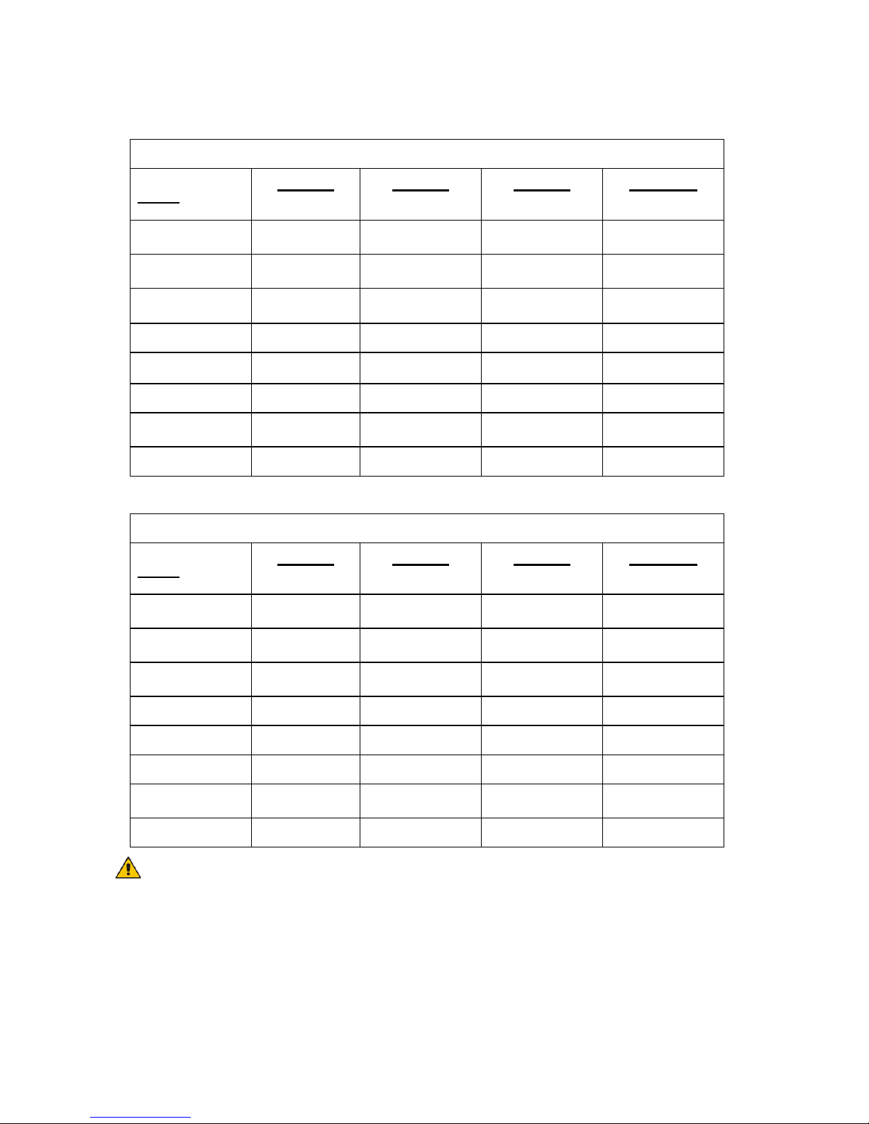
Table 4 – Boom Test Record (WITHOUT UC4+ Spray Height Control system)
Working RPM:
Boom Trial #1
[Sec]
Trial #2
[Sec]
Trial #3
[Sec]
Avg Time
[Sec]
Left UP
Left DOWN
Right UP
Right Down
Main UP
Main DOWN
Roll CW
Roll CCW
Table 5 – Boom Test Record (WITH UC4+ Spray Height Control system)
Working RPM:
Boom Trial #1
[Sec]
Trial #2
[Sec]
Trial #3
[Sec]
Avg Time
[Sec]
Left UP
Left DOWN
Right UP
Right Down
Main UP
Main DOWN
Roll CW
Roll CCW
Some sprayers may not have the Roll functions.

9
4.3 WING SENSOR INSTALLATION
1. Assemble the Breakaway Sensor Mounting
Brackets (B11) as show in Figure 4 and
Figure 5.
Figure 4 – Breakaway Sensor Bracket
Exploded View
Figure 5 – Breakaway Sensor Mounting
Bracket Assembly
To assemble the breakaway sensor bracket:
a) Assemble the bolt and nut into the collar.
b) Grease the bottom edge of the collar and
the angled tube of the base.
c) Place the collar onto the angled tube of
the mounting base.
d) Install the spring between the collar and
the upper ring of the base.
e) Insert tube through assembly and tighten
the collar
2. Mount the sensor bracket onto the boom.
If possible, mount the sensor brackets
while the booms are in their folded
position to ensure that they will not
interfere with anything when the boom
is folded for transport.
3. The sensor mounting brackets can be
installed with the mounting base behind
(Figure 8) or in front of the tube (Figure 6).
It is advised to avoid mounting the
sensor bracket to a breakaway portion
of the boom because a breakaway
action can cause the UC4+ Spray
Height Control system to force a boom
close to the ground.
Please refer to the UC4+ Spray Height
Control system warranty at the end of the
UC4+ Spray Height Control Operator’s
Manual (M01) for implications.
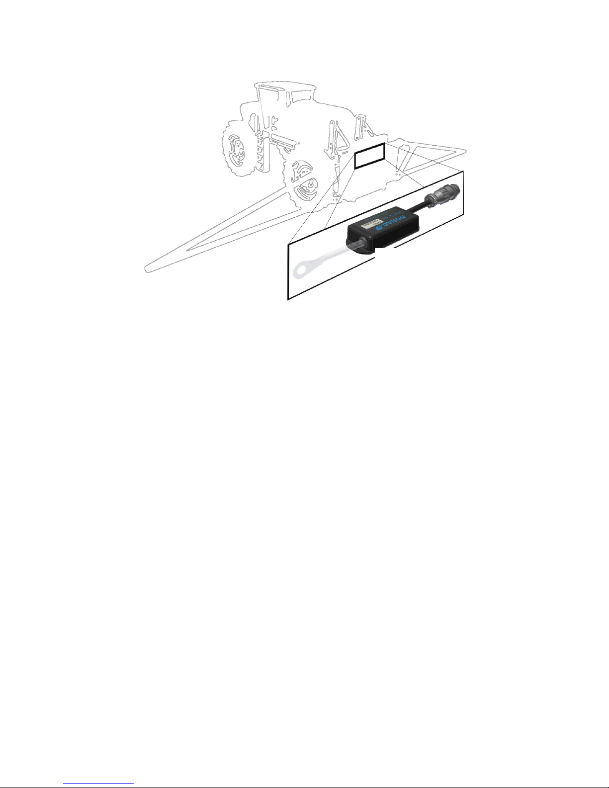
4. Mount the NORAC UC4+ ultrasonic sensor
(E02) into the sensor brackets. The sensors
should be oriented forward (ahead) of the
boom (see Figure 6 and Figure 8).
When installing the UC4+ sensors
(E02), start with the smallest serial
number on the left hand side
proceeding to the largest serial number
on the right hand side (Figure 10).
5. Sensor cables should run through the
mounting bracket tube and then behind the
member the bracket is mounted onto. Cable-
tie the connector in place. The cable must
not be allowed to hang below the boom
(Figure 6).

10
Figure 6 – Another Acceptable Mounting
Avoid mounting sensors in locations
where they may read from parts of the
boom as shown in Figure 7.
Figure 7 – Poor Mounting
(Sensor Reading off Boom)
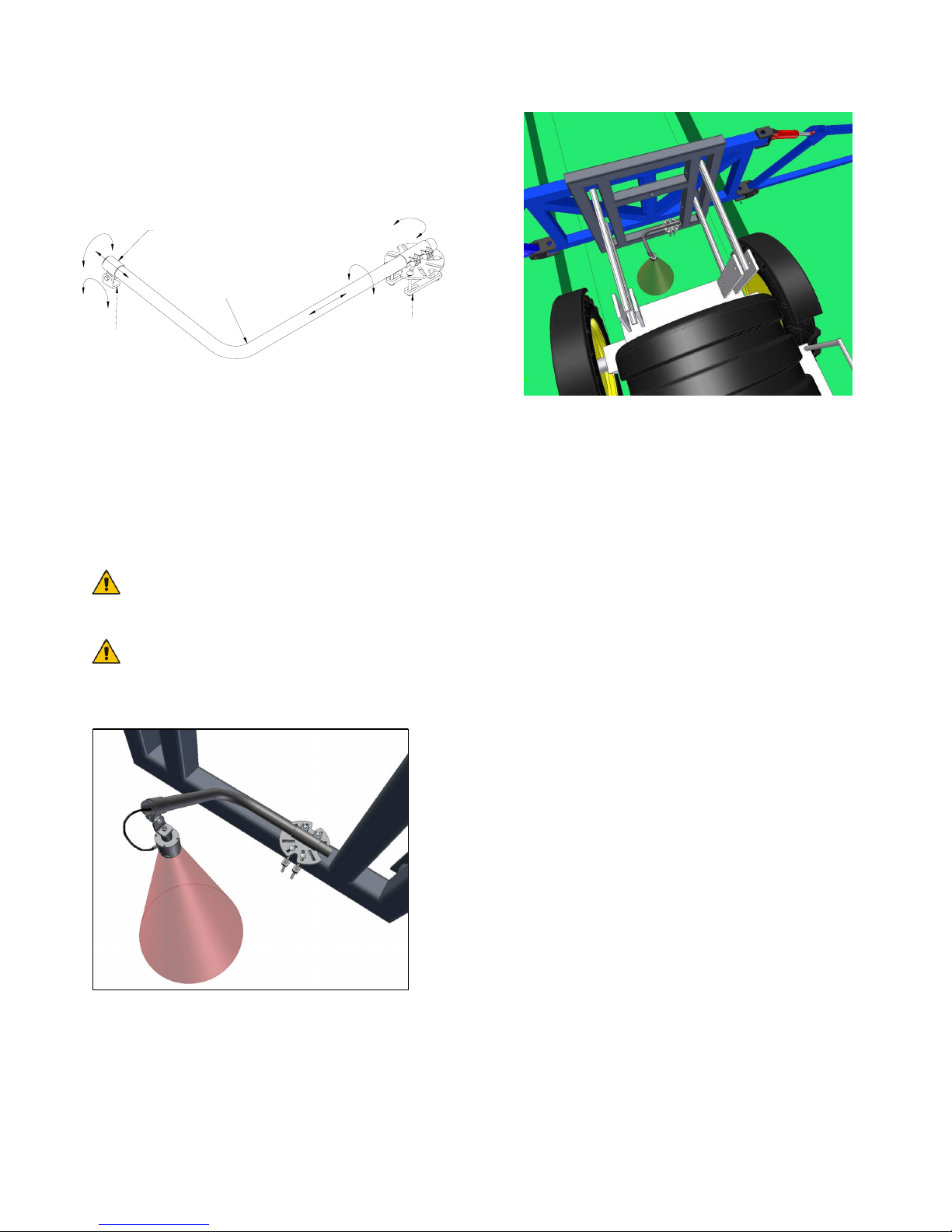
General mounting rules for UC4+
ultrasonic wing sensors:
a) In its lowest position, the sensor mouth
must be 9 inches or more from the
ground.
b) The bottom of the sensor must be at least
9 inches in front of the spray nozzles.
c) The bottom of the sensor must be at least
9 inches above the spray nozzles.
d) Ensure that there are no obstructions
within a 12-inch diameter circle projected
directly below the center of the sensor.
e) The sensor should be approximately
vertical at normal operating heights.
Figure 8 – Sensor Mounting Guidelines
AB
B
D
C
Ultrasonic
Acoustic Cone

11
Figure 9 – Spra Coupe Wing Sensor Mounting

12
Figure 10 – Sensor Serial Number Installation Location
3 SENSOR SYSTEM
5 SENSOR SYSTEM
13
4.4 MAIN LIFT SENSOR INSTALLATION
1. Assemble the main lift sensor bracket (B11)
as shown in Figure 11.
Figure 11 – Main Lift Sensor Bracket
2. The bracket can be mounted to the lowest
frame member on the center section of the
sprayer. The bracket should be mounted so
the sensor mounting collar is approximately
in the center of the sprayer and ahead of the
boom (Figure 12 and Figure 13).
The sensor mounting collar must not
be behind the sprayer’s wheel.
The General Mounting Rules for UC4+
Ultrasonic Sensors, from the previous
section, must be followed.
Figure 12 – Main Lift Sensor Bracket
Mounting Position
3. Mount the sensor onto the sensor mounting
collar (Figure 12).
Figure 13 – Main Lift Sensor Mounted in the
Correct Location
B
r
acket Tube
Sensor
Mounting Tab
Sensor Mounting
Colla
r
Bracket Base
14
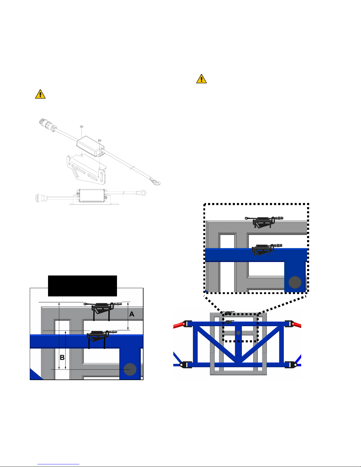
4.5 ROLL SENSOR INSTALLATION
Mount the roll sensors to the included roll
sensor brackets using the machine screws
and nylon lock nuts. (Figure 14)
The roll sensors must be mounted
tightly to the brackets.
Figure 14 – Mounting the Roll Sensor to the
Roll Sensor Mounting Bracket
When mounting the roll sensors use the
following guidelines and refer to Figure 15.
a) The smaller the distance between Aand
Bin Figure 15, the better the
performance will be.
Distance A can not be more than 12”.
b) The roll sensors must not be mounted
below the pivot point.
c) Ensure the roll sensors are sitting
relatively level when the sprayer chassis
and boom are level.
d) Both roll sensors must be mounted with
the circular AMP connector facing
towards the Right-Hand Wing (when
looking from the rear of the sprayer).
Figure 15 – Mounting Guidelines for Center Pivot Sprayers
Connectors towards
Right-hand Wing Æ
15
Figure 16 – Roll Sensor Mounting with Respect to Sprayer Orientation
4.5.1 Boom Roll Sensor Mounting
The boom roll sensor (E04) must be
mounted to the rotating part of the boom.
Follow these guidelines and refer to
Figure 17 to mount the sensor.
a) Make sure you are using the roll
sensor that does NOT have a
temperature probe (only one cable)
(E04).
b) The boom roll sensor must be
mounted to the rotating part of the
boom suspension.
c) Use cable-ties to secure the bracket
to a square edge feature (square
tube).
d) Ensure the AMP (circular)
connector exits towards the Right
Hand Wing (when looking from the
rear of the sprayer).
e) Securely cable-tie the connector to
the frame.
4.5.2 Chassis Roll Sensor Mounting
The chassis roll sensor must be mounted
to a non-rotating part of the boom. To
mount the chassis roll sensor, follow the
following guidelines and refer to Figure
17.
a) Make sure you are mounting the roll
sensor that does have a temperature
probe (2 cables) (E03).
b) Mount the chassis roll sensor (E03)
to a non-rotating part of the boom.
c) Cable-tie the bracket to a square
edge feature (square tube).
d) The AMP (circular) connector
MUST exit towards the Right Hand
Wing (when looking from the rear).
e) Securely cable-tie the connector to
the frame.
* The boom frame
roll sensor does not
have a temperature
probe

16
Figure 17 – Boom and Chassis Roll Sensors Correclty Mounted
4.5.3 Inverted Roll Sensor Mounting
If desired, the Roll sensor may be
mounted inverted, so long as the
connector exits towards the right-hand
boom. Inverted mounting may be used
to optimize the mounting criteria
explained in Section 4.5.
Figure 18 – Inverted Roll Sensor Mounting may be Applicable in Order for Optimal
Performance
E04
E03

17
4.5.4 Temperature probe
Fasten the temperature probe (E03) to the UC4
valve block using the included 3/8x1/2” bolt as
illustrated in Figure 19.
Figure 19 – UC4+ Valve Block with
Temperature Probe Installed
Other manuals for UC4+
41
Table of contents
Other Norac Farm Equipment manuals

Norac
Norac UCB Sx275 User manual

Norac
Norac UC4+ User manual

Norac
Norac UC4 Total Control User manual

Norac
Norac UC5 Topcon X30 User manual

Norac
Norac UC5 Topcon X30 User manual

Norac
Norac UC5 Sx275 User manual

Norac
Norac UC4.5 User manual

Norac
Norac UC5 Topcon X30 User manual

Norac
Norac UC4+ User manual

Norac
Norac UC4.5 User manual
Popular Farm Equipment manuals by other brands

Schaffert
Schaffert Rebounder Mounting instructions

Stocks AG
Stocks AG Fan Jet Pro Plus 65 Original Operating Manual and parts list

Cumberland
Cumberland Integra Feed-Link Installation and operation manual

BROWN
BROWN BDHP-1250 Owner's/operator's manual

Molon
Molon BCS operating instructions

Vaderstad
Vaderstad Rapid Series instructions


