Norac UC5 Topcon X30 User manual
NORACUC5Operator’sManual

Copyright2018byNORACSystemsInternationalInc.
ReorderP/N:UC5‐BC‐MANUAL‐OPERATORRevD
NOTICE:NORACSystemsInternationalInc.reservestherighttoimproveproductsandtheirspecificationswithoutnoticeandwithouttherequirementtoupdateproductssold
previously.Everyefforthasbeenmadetoensuretheaccuracyoftheinformationcontainedinthismanual.Thetechnicalinformationinthismanualwasreviewedatthetime
ofapprovalforpublication.

1
TableofContents
SafetyPrecautions...................................................................................................................................2
TechnicalSpecifications...........................................................................................................................4
UC5Operation.........................................................................................................................................6
NORACSolutions....................................................................................................................................29
UC5SystemServiceandDiagnostics.....................................................................................................31
UC5SystemMaintenance......................................................................................................................51
UC5MenuStructure..............................................................................................................................54
IconDescriptions...................................................................................................................................60
ContactingSupport................................................................................................................................64
Notes......................................................................................................................................................65

2
1SafetyPrecautions
TheUC5™BoomHeightControlsystemwillgreatlyimproveyoursprayingheightaccuracyandprotect
theboomagainstdamageinawidevarietyoffieldconditions.However,undersomecircumstances
performancemaybelimited.Theoperatorofthesprayermustremainalertatalltimesandoverride
theautomaticcontrolwhennecessary.
Important
UndernocircumstancesshouldanyserviceworkbeperformedonthemachinerywhiletheUC5Boom
HeightControlsystemisinautomaticmode.
AlwaysensurethattheUC5BoomHeightControlsystemispowereddownorinmanualmode:
Beforeleavingtheoperator’sseat.
Whilethemachineisnotmoving.
Whentransportingthemachine.
Beforeworkingonanypartofthebooms:
SettheUC5systemtomanualmode.
Turnthesprayerengineoff.

3
Tofullyunderstandyournewsystemanduseittoitsfullestcapacityitisrecommendedthatyoureadthis
manual.Thismanualprovidesageneraloverview,keyfeatures,operatinginstructions,assistancewith
systemsetup,regularmaintenancerecommendationsandtroubleshooting.
Everyefforthasbeenmadetoensuretheaccuracyofthisdocumentatthetimeofpublication.NORAC
Systemsassumesnoresponsibilityforomissionsanderrors.Norisanyliabilityassumedfordamages
resultingfromtheuseofinformationcontainedherein.
Ifyouhaveanyquestions,feedbackorcommentsregardingtheUC5™BoomHeightControlsystem,
pleasecontactanyofthenumbersbelow.
Phone: 8889799509
Web: www.norac.ca

4
2TechnicalSpecifications
CANICES‐3(A)/NMB‐3(A)
Thisdevicecomplieswithpart15oftheFCCRules.Operationissubjecttothefollowingtwoconditions:
(1)Thisdevicemaynotcauseharmfulinterference,and(2)thisdevicemustacceptanyinterference
received,includinginterferencethatmaycauseundesiredoperation.
ThisequipmenthasbeentestedandfoundtocomplywiththelimitsforaClassAdigitaldevice,pursuant
topart15oftheFCCRules.Theselimitsaredesignedtoprovidereasonableprotectionagainstharmful
interferencewhentheequipmentisoperatedinacommercialenvironment.Thisequipmentgenerates,
uses,andcanradiateradiofrequencyenergyand,ifnotinstalledandusedinaccordancewiththe
instructionmanual,maycauseharmfulinterferencetoradiocommunications.Operationofthis
equipmentinaresidentialareaislikelytocauseharmfulinterferenceinwhichcasetheuserwillbe
requiredtocorrecttheinterferenceattheirownexpense.
ThisClassAdigitalapparatuscomplieswithCanadianICES‐003.
PursuanttoEMCDirective–Article9,thisproductisnotintendedforresidentialuse.
5
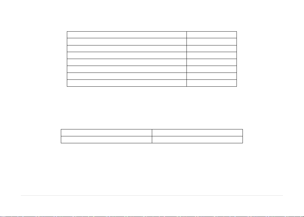
Table1:SystemSpecifications
SupplyVoltage(rated)12VDC
SupplyCurrent(rated)10A
HydraulicPressure(maximum)3300psi
BaudRate250kbps
ClockFrequency(maximum)96MHz
SolenoidValvePWMFrequency300Hz
UltrasonicSensorTransmitFrequency50kHz
OperatingTemperatureRange0°Cto80°C
The10Afuseonthepowercablemaybereplacedbytheoperatorifneeded.Thereplacementfusemust
beratedtoblowinlessthan120secondsat200%andbeANSI/UL248‐14orbetter.
Table2:ReplacementFuse
NORACPartNumber106676
ManufacturerPartNumberLittelfuse–0287010.PXCN
TheUC5™productlineiscoveredbymultiplePatentsincluding,butnotlimitedtothefollowing:
U.S.Pat.No:US200415838,US88432831
EuropeanPat.No:EP1444894,EP2630856
CanadianPat.No:CA2418610

6
3UC5Operation
NOTE:Somefunctionsandfeaturesmaynotbeavailableforallsprayermakesandmodels.Consultyour
salesrepresentativeortechnicalsupportwithanyquestionsorconcerns.
3.1. InitialStartUp
Ontheinitialstartupandafterconfirmingthelegaldisclaimer,ascreenwillappearinformingthe
operatorthatanautomaticsetupmustbeperformed.Afterconfirmingthisscreen,theautomaticsetup
willbegin.Theautomaticsetupreminderatstartupwillalsobeshowneachtimeafirmwareupdateis
performed.
3.2. MainRunScreen
Oncethesystemiscorrectlyconfigured,itisverysimpletouse.Afterconfirmingthelegaldisclaimer,the
runscreenwillappear.Foravirtualterminal,fromthedisplay’sstartupscreen,selecttheUC5™icon.An
imageoftheboomwiththeheightofeachboomsectionisdisplayedasshowninFigure1.
Tochangebetweenautomaticandmanualmode,selectthecorrespondingAUTO(A)orMANUAL(M)
button.WhentheUC5systemisinmanualmode,theheightdisplayedundereachboomsectionis
measuredfromthespraynozzlestothesoil(SoilMode™)orcropcanopy(CropMode™orHybrid
Mode™).Iftherearefiveheightsensorsonthesprayer,theheightdisplayedistheaverageforeach
boomsection.
WhentheUC5systemisinautomaticmode,arrowswillappearonthescreenaboveorbelowtheboom
sections.ThesearrowsindicatetheUC5systemismakingacorrectiontopartoftheboominthe
displayeddirection.Oftenthecorrectionwillbeverysmallandtheremaynotbeanoticeablechangein
boomposition.

7
Figure1:NORACUC5RunScreen–ManualMode
Figure2:NORACUC5RunScreen–AutomaticMode
Theheightdisplayedundertheboomintheupperrightcornerisknownasthetargetheight.Thisis
measuredfromthespraynozzlestothesoil(SoilMode™)ortothecropcanopy(CropMode™orHybrid
Mode™).Thecropatthebottomofthescreenindicatesthemodethecontrollerisin.Ifthegreenlineis
abovethecrop,thesystemisinCropMode.Ifthegreenlineisbelowthecrop,thesystemisinSoil
Mode.Ifthegreenlineisbothaboveandbelowthecrop,thesystemisinHybridMode.
ThefollowingappliestoVirtualTerminalonly:
Whentwoormorevirtualterminalsareconnectedonthedisplaybus,themovetonextVTbuttonwill
appearonthesoftkeyareaoftherunscreen.Thisbuttonallowstheusertoselectthepreferredterminal
onwhichtodisplaytheUC5™screen.BypressingthisbuttontheUC5screenwillmovetonextavailable
terminal.
AUTO
Button
MANUAL
Button
Settings
Button
Boom
Height
and
State

8
3.3. ErrorIndicators
Ifanerrorisdetectedinthesystem,theerrorbuttonwillappearonthescreenasshowninthefigures
below.Theboomwiththeerrorwillgotoitsmanualstatewiththe‘M’or‘A’onthedisplayflashing
dependingonwhetherthesystemisinautoormanualmode.
Figure3:ErrorIndicator
Figure4:SampleErrorViewingScreen
Selectingtheerrorbuttonallowsallactivesystemerrorstobeviewed.Tonavigatebetweenmultiple
errors,usethenextandpreviousarrowbuttons.
Iftheboomisabovenormalworkingheight(typically60inches/152cm)whenautomaticmodeis
engaged,awarningmessagewillappearrequiringtheboomtobeloweredbeforeallowingautomatic
modetobeactivated.

9
Figure5:OverHeightWarning
3.4. SprayerManualBoomSwitches
Whenamanualswitchispressed,anarrowwillbedisplayedonthescreenshowingwhichfunctionis
beingactivated.
Whileinautomaticmodeifeitherleftorrighttiltswitchesarepressed,thecorrespondingboomsection
willgointomanualmode.Ifthemainliftswitchisheldwhileinautomaticmode,theentiresystemwill
gointomanualmode.Toreturnallboomsectionstoautomaticmode,presstheautobutton.
10
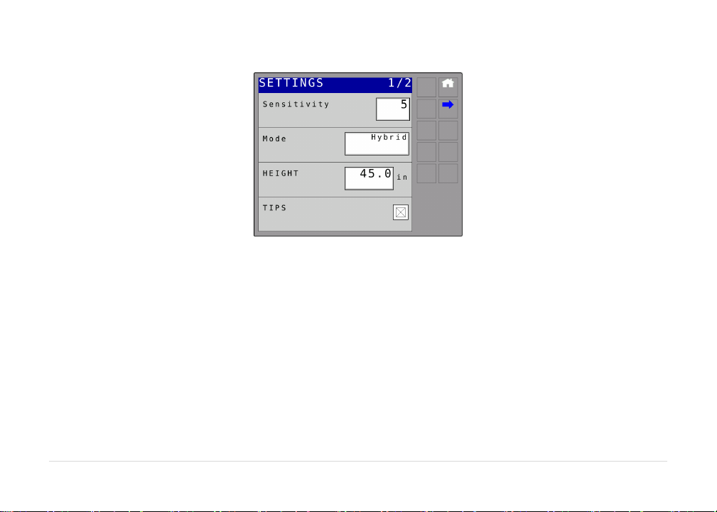
3.5. Settings
Figure6:SettingsScreen
Sensitivity:
Thesensitivitycanbeadjustedfrom1to10,with5beingthedefaultsetting.Alowernumberwillreduce
thesystemsensitivityandimprovestability.Highersettingswillspeeduptheresponse.
Mode:
ThemodebuttonallowsthesystemtobechangedbetweenSoilMode™,CropMode™andHybrid
Mode™.SoilModeallowsthesensorstoreadaheightfromthespraynozzlestotheground.CropMode
willreadtheheightfromthespraynozzlestothetopofthecropcanopy.HybridModeusesa
combinationofthecropandsoilreadings.

11
Height:
Theheightisthetargetheightthattheoperatorwouldliketheboomtobesetatwhensprayingin
automaticmode.
InHybridMode™,thetargetheightisacombinationofmeasurementstoprovideamorestableestimate
ofthedistancefromthecropcanopytothesprayernozzles.
TipsOn/Off:
Somesprayershavetheabilitytofoldintheboomtipsandspraywithonlytheinnersectionsofthe
boom.Ifthesprayerhasthisabilityandisequippedwithafivesensorsystem,thecheckboxshouldbe
uncheckedwhensprayingwiththetipsfoldedin(tipsoff).
Whenintipsoffthetwooutersensorsonthewingswillbedisabledandonlytheinnerwingsensorswill
beusedtocontroltheheight.
Thecheckboxisdefaultedtobechecked(tipson)andwillreturntobecheckedanytimethepoweris
cycled.
12
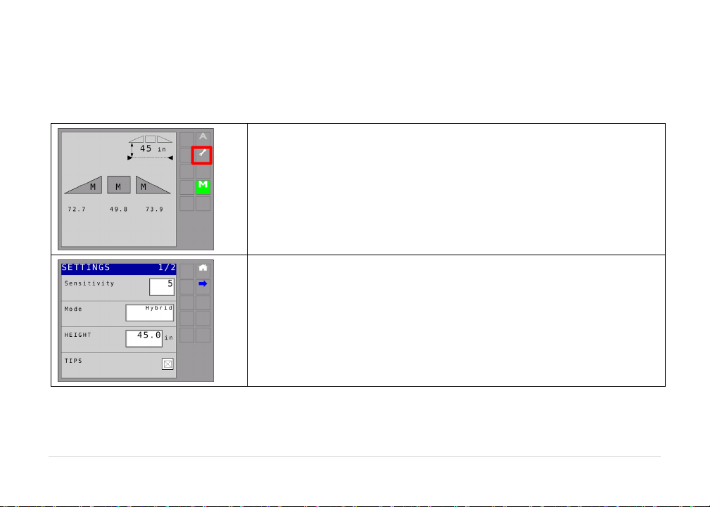
3.6. NavigatingtotheUC5SetupMenu
Toperformeithertheautomaticormanualsystemsetup,theusermustnavigatetothesetupscreen.The
systemmustbeinmanualmodetoperformsetups.
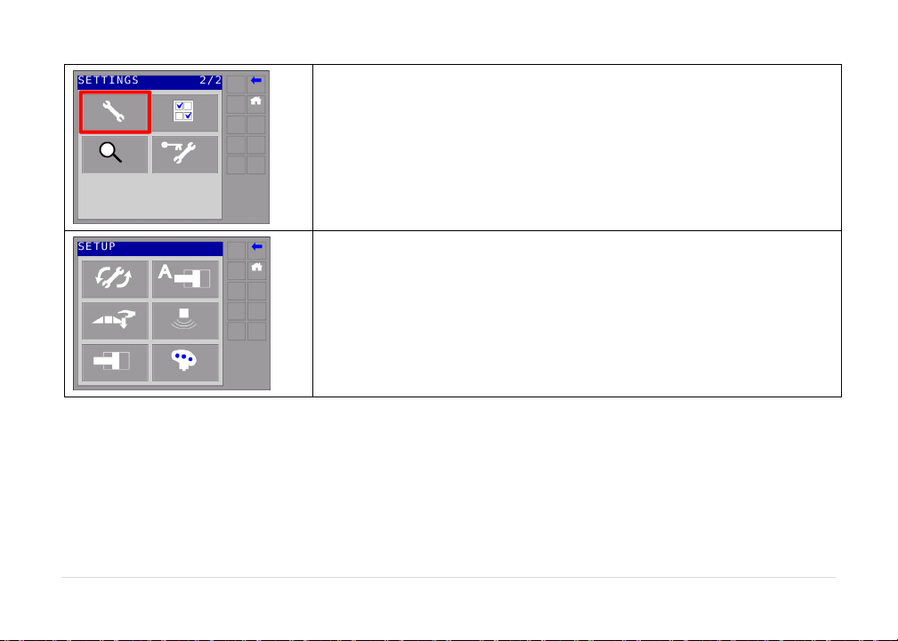
Whenthesystemisinmanualmode,selectthesettingsbutton.
Selectthenextbutton.
13
Selectthesetupbutton.
Thesetupscreenwillbedisplayed.

14
3.7. AutomaticSystemSetup
Allboomsectionswillmoveduringtheautomaticsetup.
Peopleandequipmentmustbeclearofsprayerboom.
Ensuretheboomshavesufficientrangetoliftfullyandareclearofanypowerlines.
Unfoldthesprayerinalocationthatisrelativelylevelandwherethesensorsareoverbaresoilorgravel.
Donotconducttheretuneoverstandingcrop,weedsorgrass.Also,avoidconcreteorasphaltsurfaces.
Ensuretheboomrollsuspensionsystemisfunctioningproperlyandsmoothly.Frictiononwearsurfaces
canberelievedusinglubricants(grease,etc.)oradjustment.Properlytunedsuspensionsystemswill
optimizeUC5™performance.
Forbestresults,thehydraulicsystemshouldbeunderanormalloadandatanormalworking
temperature.
Startthesolutionpumpandrunthesprayer’sengineatanormalworkingRPMfortheentire
setup.
Cycleallboomsectionsupanddownmanuallyforfiveminutestowarmtheoil.
Fortrailedsprayers,ensureanyhydraulicflowcontrolsareadjustedfornormalfieldoperation.
ChangingthehydraulicflowcontrolsafterorduringthesystemsetupwillaffecttheUC5
performance.
15
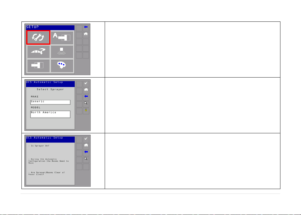
Selectautomaticsetup.
Selectthesprayermakeandmodelfromthelists.
Thenselectthecheckbutton.
Alistofprecautionswillbedisplayedonthedisplay.Itisvery
importantthatyoureadtheseprecautionsandfollowthem.
Onceyouhavereadtheprecautions,selectthecheckbutton.
Atanypointthemagnifyingglasscanbepressedtoobtainmore
detailedinformationofthesetupprocedureortoviewanyerrors.
16
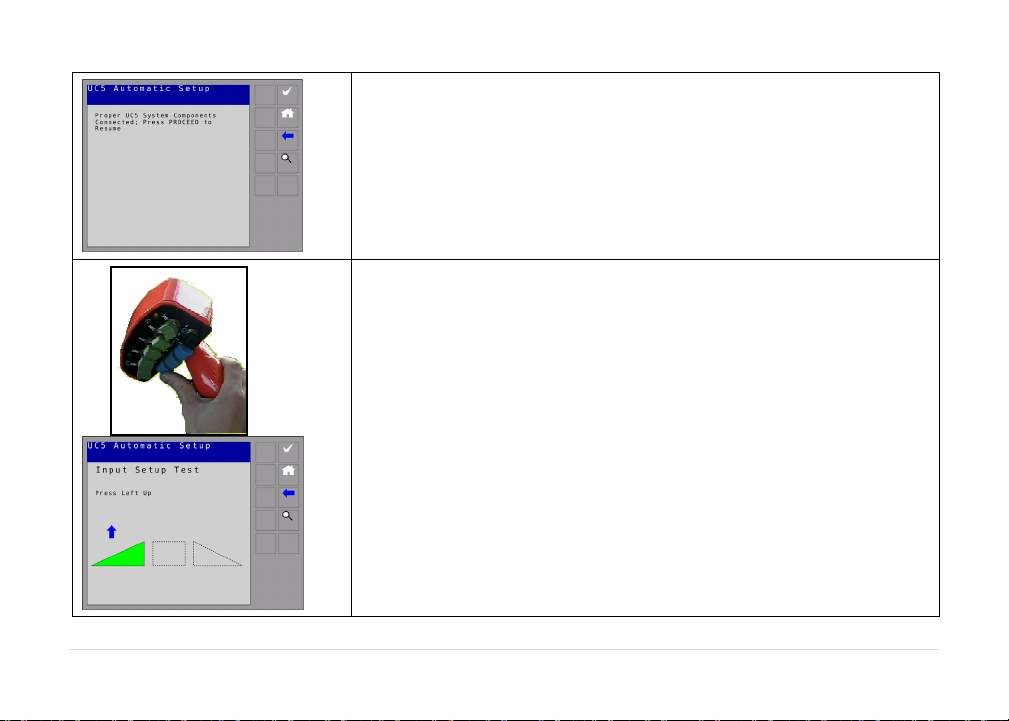
Alistofconnectedmoduleswillbedisplayed.Makesurethe
modulesmatchyoursystemmodules(ECHO™only).
Ifthelistofmodulesmatchesthecurrentlyinstalledmodules,press
thecheckbutton.
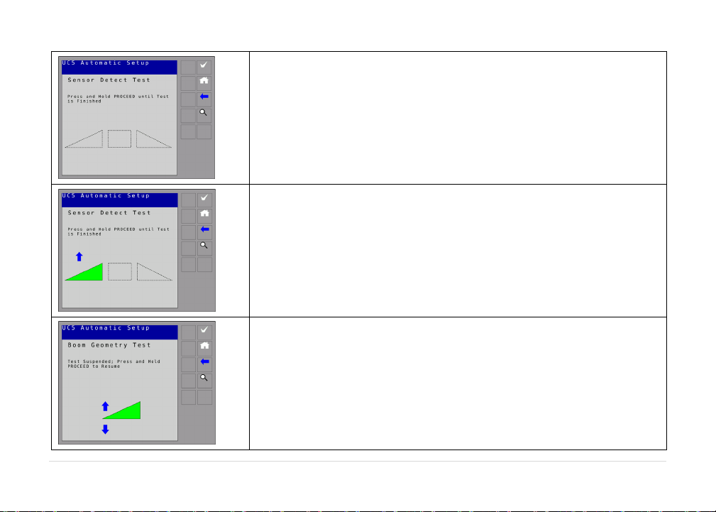
Thesystemwillinstructyoutomoveboomfunctionsusingthe
sprayercontrols.Moveeachboomasinstructedontheterminal.
17
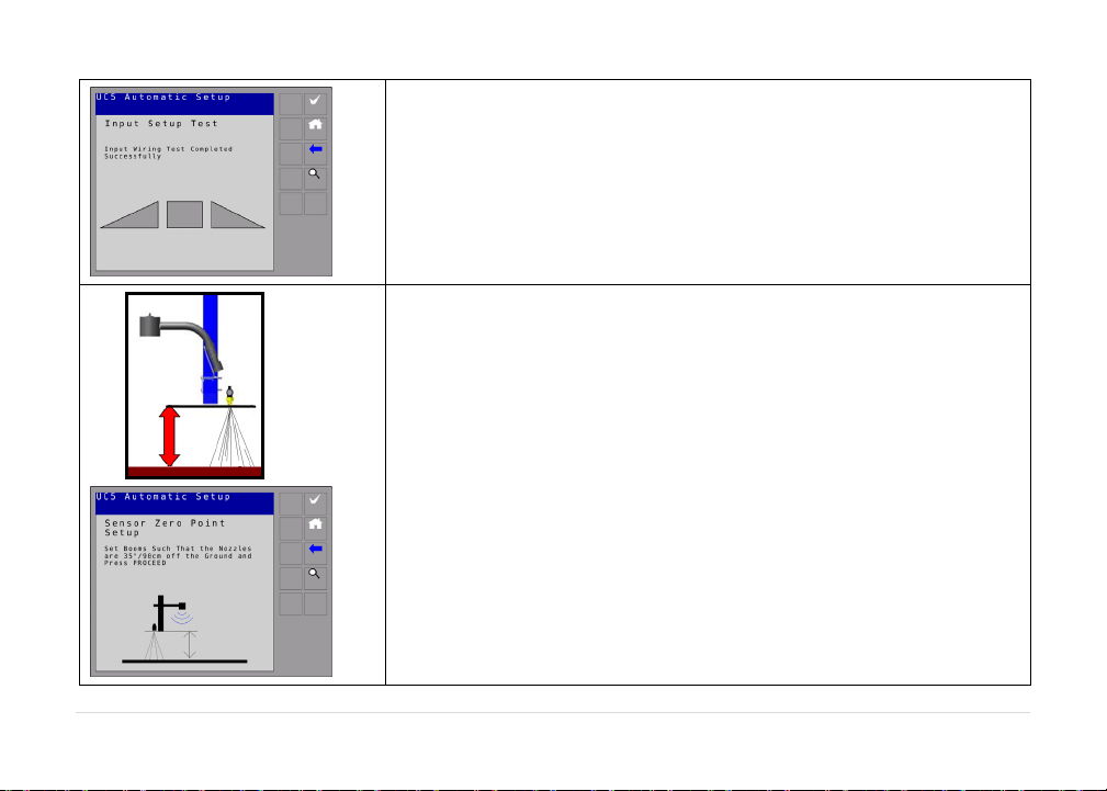
Thesetupwillcontinueautomaticallywhentheswitchtestis
finished.
Youwillthenbeinstructedtoplaceyourboomssothenozzlesare
35”(90cm)fromtheground.Adjustthedistancefromthenozzleto
thegrounddirectlybeneath.Ensureyouareoverbare,flatsoil.
Whenthemeasureddistanceis35”(90cm)selectcheckbutton.
35”
90cm
18
Youwillthenbeinstructedtoholdthecheckbutton.Continue
holdingwhileeachboomsectionismoved.
Thedisplaywillshowanarrow.Atthistimetheboomwillbein
motion.Whenitisdonethedisplaywillinstructyoutoreleasethe
checkbutton.Donotmovetheboomsatthistime.
Youwillthenbeinstructedtoholdthecheckbutton.Theterminal
willdisplay“cruising”.
Other manuals for UC5 Topcon X30
55
Table of contents
Other Norac Farm Equipment manuals

Norac
Norac UC5 Sx275 User manual

Norac
Norac UCB Sx275 User manual

Norac
Norac UC4+ User manual

Norac
Norac UC5 Topcon X30 User manual

Norac
Norac UC4.5 User manual

Norac
Norac UC4.5 User manual

Norac
Norac UC4+ User manual

Norac
Norac UC4 Total Control User manual

Norac
Norac UC4+ User manual

Norac
Norac UC5 Topcon X30 User manual
Popular Farm Equipment manuals by other brands

Schaffert
Schaffert Rebounder Mounting instructions

Stocks AG
Stocks AG Fan Jet Pro Plus 65 Original Operating Manual and parts list

Cumberland
Cumberland Integra Feed-Link Installation and operation manual

BROWN
BROWN BDHP-1250 Owner's/operator's manual

Molon
Molon BCS operating instructions

Vaderstad
Vaderstad Rapid Series instructions


