Norac UC4+ User manual

PLA MAP II 3250 F
Installation Manual
Spray Height Controller
Improving the competitiveness o Industry and Agriculture
through Precision Measurement

Printed in Canada
Copyright 2005-08 by NORAC Systems International Inc.
Reorder P/N: UC4+BC+PL1-INST Rev B (PLA MAP II 3250 F)
NOTICE
NORAC Systems International Inc. reserves the right to improve products and their specifications without notice and without the
requirement to update products sold previously. Every effort has been made to ensure the accuracy of the information contained
in this manual. The technical information in this manual was reviewed at the time of approval for publication.

TABLE OF CONTENTS
1
INTRODUCTION..................................................................................................................................1
2
GENERAL SYSTEM DESCRIPTION ..................................................................................................2
3
PARTS LISTS ......................................................................................................................................4
4
INSTALLATION PROCEDURE...........................................................................................................8
4.1
WING SENSOR INSTALLATION.........................................................................................................8
4.2
MAIN LIFT SENSOR INSTALLATION......................................................................................11
4.3
ROLL SENSOR INSTALLATION.......................................................................................................12
4.3.1
Boom Frame Roll Sensor Mounting......................................................................................13
4.3.2
Chassis Roll Sensor Mounting..............................................................................................14
4.4
HYDRAULIC INSTALLATION ...........................................................................................................15
4.4.1
Valve Assembly.....................................................................................................................15
4.4.2
Valve Mounting......................................................................................................................15
4.4.3
Hydraulic Plumbing ...............................................................................................................16
4.5
ELECTRICAL INSTALLATION..........................................................................................................17
4.6
COMPLETING THE INSTALLATION ..................................................................................................21
5
ELECTRICAL REFERENCE – CABLE DRAWINGS........................................................................22
5.1
ITEM C02: 44668 –SENSOR BRANCH CABLE...............................................................................22
5.2
ITEM C02B: 44664 -CABLE UC4 CAN NODE DUAL.....................................................................22
5.3
ITEM C03: 44656 –CABLE VALVE VARIABLE RATE......................................................................23
5.4
ITEM C10: 44650-39 –CABLE POWER GENERIC SELF-PROPELLED..............................................24
5.5
ITEM C11: 44651-03 –CABLE EXTENSION CABLE VALVE GENERIC..............................................25
5.6
ITEM C14: 44658-28 –CABLE INTERFACE UC4 BC C14 POWER PIGTAIL.....................................26
5.7
ITEM C12: 44658-38 –CABLE INTERFACE UC4 BC C12 DIN ALL...............................................27
5.8
ITEM C16: 44658-39 –CABLE INTERFACE UC4 BC C16 DIN.......................................................28
6
APPENDIX A – VALVE CONNECTOR CHANGE.............................................................................29

1
1
INTRODUCTION
Congratulations on your purchase of the NORAC UC4+ Spray Height Controller. This system is
manufactured with top quality components and is engineered using the latest technology to
provide operating features and reliability unmatched for years to come.
When properly used the system can provide protection from sprayer boom damage, improve
sprayer efficiency, and ensure chemicals are applied correctly.
Please take the time to read this manual completely before attempting to install the system. A
thorough understanding of this manual will ensure that you receive the maximum benefit from
the system.
YOUR INPUT CAN HELP MAKE US BETTER! If you find issues or have suggestions
regarding the parts list or the installation procedure, please don’t hesitate to contact us via
the information given below:
Phone: +1-306-664-6711 all other regions
E-mail: [email protected]
Website: www.norac.ca

2
2
GENERAL SYSTEM DESCRIPTION
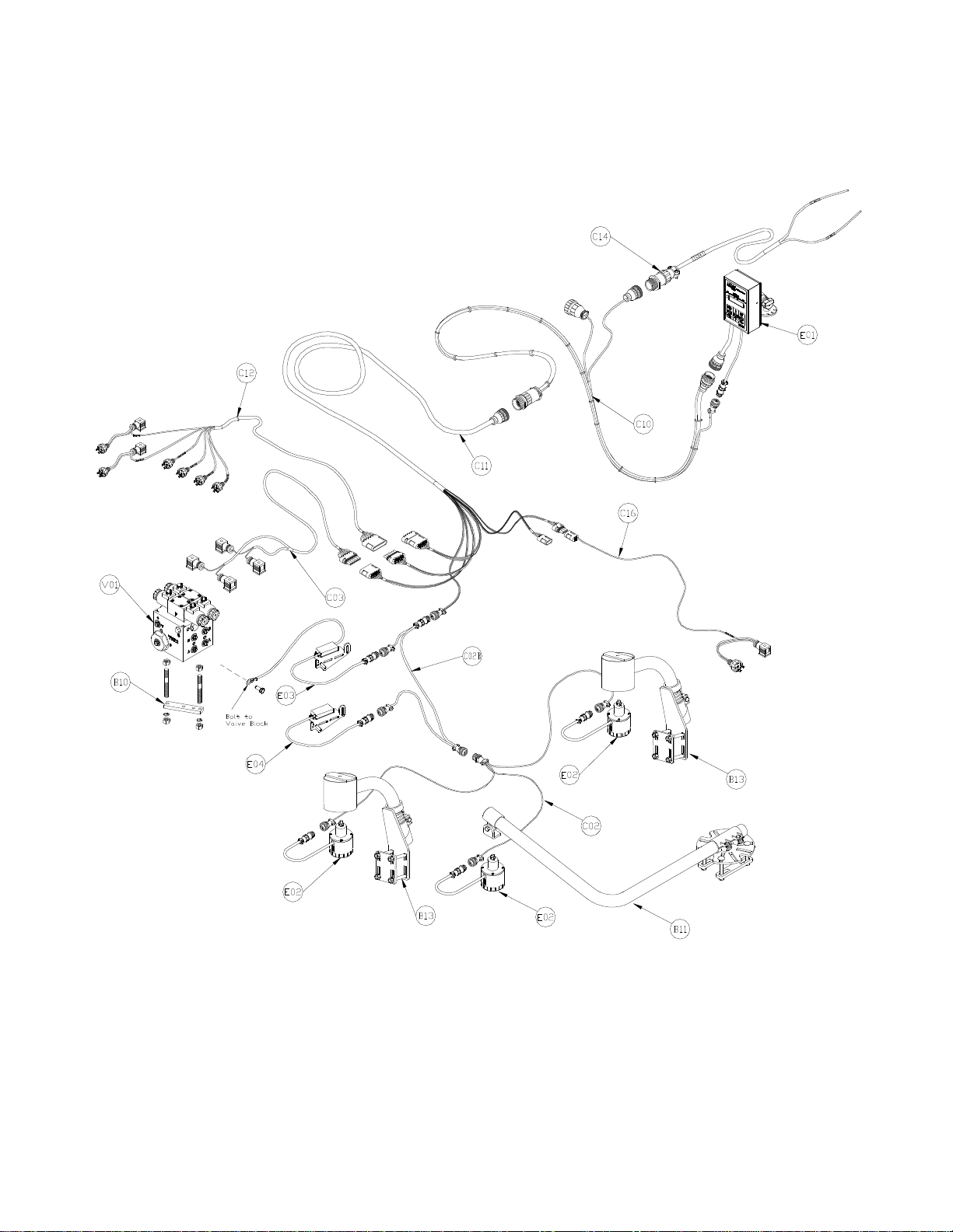
Figure 1 depicts the general system layout of the UC4+ Spray Height Control system.
Figure 1 – System Components and General Location
NOTICE:
Every effort has been made to ensure the
accuracy of the information contained in this
manual. All parts supplied are selected
specially to fit the sprayer to facilitate a
complete installation. However, NORAC
cannot guarantee all parts fit as intended due
to the variations of the sprayer by the
manufacturer. Please read this manual in
its entirety before attempting installation.
ATTENTION:
When installing the UC4+ Spray Height
Control system please be aware that at a
point in the installation your sprayer booms
will be inoperative until the installation is
complete. Any installation procedure
requiring boom movement will need to be
done first. Once the hydraulics have been
disconnected you must complete the
electrical installation before the booms
become operative.

4
3
PARTS LISTS
The parts that come with your UC4+ Sprayer Boom System are listed in Table 1. The item number on
the left side of this table references each part.
Please ensure that all parts in your kit are present before proceeding with your installation.
Table 1 – PLA MAP II 3250 F Sprayer Boom Control System Parts (Rev A)
Item Part Number Name Quantity
B05 44706-01 KIT CABLE TIE BLACK 10 PCS 21 IN 150 PCS 7 5 IN 1
B10 44700-06 BRACKET VALVE MOUNTING STD 1
B11 44743 MOUNTING BRACKET MAIN LIFT SENSOR UC4 PLUS 1
B13 44728 MOUNTING BRACKET COMPLETE UC4 BREAKAWAY EXTENDED 2
B14 44724 BRACKET BREAKAWAY SPACER 2IN WITH BOLTS 2
C02 44668 CABLE UC3 SENSOR BRANCH 1 AMP RECEPT 3 AMP PLUG BC 1
C02B 44664 CABLE UC4 CAN NODE DUAL 1
C03 44656D CABLE VALVE VARIABLE RATE DT 1
C10 44650-39 CABLE POWER GENERIC SELF-PROPELLED 1
C11 44651-03 CABLE EXTENSION VALVE GENERIC 1
C12 44658-38 CABLE INTERFACE UC4 BC C12 DIN ALL 1
C14 44658-28 CABLE INTERFACE UC4 BC C14 POWER PIGTAIL 1
C16 44658-39 CABLE INTERFACE UC4 BC C16 DIN 1
E01 4461BC+ UC4 PLUS BOOM CONTROL PANEL 1
E02 44631 UC4 ULTRASOUND SENSOR 3
E03 44641 UC4 PLUS ROLL SENSOR W TEMPERATURE PROBE 1
E04 44642 UC4 PLUS ROLL SENSOR 1
H01 44863-01 HOSE ASSEMBLY 122R2-06 36 IN L 6FJX 6FJX 2
H02 44862-14 HOSE ASSEMBLY 122R2-04 36 IN L 4FJX 4FJX 2
H20 44865-45 HYDRAULICS FITTING KIT - PL1 1
M01 UC4+BC+PL1-INST MANUAL INSTALLATION UC4+ PLA MAP 1
M01A 446BC+MAN6-1 MANUAL UC4+ BOOM CONTROL 2008 OPERATORS SMALL BOOKLET 1
M01B 446BC+MAN6-2 MANUAL UC4+ BOOM CONTROL 2008 QUICK REFERENCE SMALL BOOKLET 1
V01 44933D VALVE BLOCK ASSEM UC5-BC 2-STATION CC/LS VARIABLE RATE DT CONNECTORS 1

5
Table 2 – 44865-45 (Rev A) - Hydraulics Fittings Kit Details
Item Part Number Name Quantity
Picture
F01 103719 MALE ADAPTER - 6MB 4MJ 4
F02 104704 FEMALE JIC CAP - 4FJCN 4
F03 103194 MALE ADAPTER - 6MJ 8MB 2
F04 103993 MALE ADAPTER - 4MJ 4MJ 2
F07 103312 MALE ADAPTER - 6MB 6MJ 2
F08 44928 ORIFICE INSERT 047 IN ONE WAY 4
6 M B - 6 M OR X 90
SIZE IN
1/16
TH'S
GENDER: MALE
OR FEMALE
90
°
ANGLE
SWIVEL
TYPE
GENDER
SIZE
TYPE:
B - ORB
J - JIC
OR - FLAT
FACE
P - PIPE
Fitting Name
Example:
6
The parts that come with your UC4 System are shown below in their general installation
configuration.
Figure 2 – UC4+ Spray Height Control system Components
*If your valve connectors or cables appear different than shown, refer to Appendix A for more
details.
7
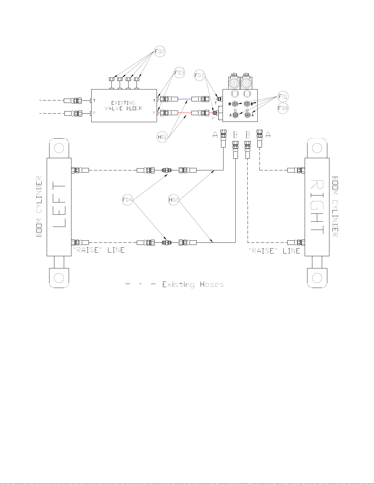
Figure 3 - Hydraulic Plumbing Schematic

8
4
INSTALLATION PROCEDURE
4.1 W
ING
S
ENSOR
I
NSTALLATION
1. Assemble the Breakaway Sensor
Mounting Brackets (B11) as show in
Figure 4 and Figure 5.
Figure 4 – Breakaway Sensor Bracket
Exploded View
Figure 5 – Breakaway Sensor Mounting
Bracket Assembly
To assemble the breakaway sensor
bracket:
a) Assemble the bolt and nut into the
collar.
b) Grease the bottom edge of the collar
and the angled tube of the base.
c) Place the collar onto the angled tube
of the mounting base.
d) Install the spring between the collar
and the upper ring of the base.
e) Insert tube through assembly and
tighten the collar
2. Mount the sensor bracket onto the boom.
If possible, mount the sensor
brackets while the booms are in
their folded position to ensure that
they will not interfere with
anything when the boom is folded
for transport.
3. The mounting brackets can be installed
with the mounting base behind (Figure
9) or in front of the tube (Figure 7).
4. Use the sensor bracket breakaway spacer
(B14) to mount the sensor bracket
(Figure 6).
Figure 6 - Mounting the Sensor
Breakaway Bracket with spacer
Breakway
Bracket
Spacer

9
5. Mount the NORAC UC4+ ultrasonic
sensor (E02) into the sensor brackets.
The sensors should be oriented forward
(ahead) of the boom (see Figure 7 and
Figure 9).
When installing the UC4+ sensors
(E02), start with the smallest serial
number on the left hand side
proceeding to the largest serial
number on the right hand side
(Figure 10).
6. Sensor cables should run through the
mounting bracket tube and then behind
the member the bracket is mounted onto.
Cable-tie the connector in place. The
cable must not be allowed to hang below
the boom (Figure 7).
Figure 7 – Another Acceptable Mounting
Avoid mounting sensors in
locations where they may read
from parts of the boom as shown
in Figure 8.
Figure 8 – Poor Mounting
(Sensor Reading off Boom)
General mounting rules for UC4+
ultrasonic sensors:
a) In its lowest position, the sensor
mouth must be 9 inches or more
from the ground.
b) The bottom of the sensor must be at
least 9 inches in front of the spray
nozzles.
c) The bottom of the sensor must be at
least 9 inches above the spray
nozzles.
d) Ensure that there are no obstructions
within a 12-inch diameter circle
projected directly below the center of
the sensor.
e) The sensor should be approximately
vertical at normal operating heights.
Figure 9 – Sensor Mounting Guidlines
A
B
B
D
C
Ultrasonic
Acoustic Cone
10
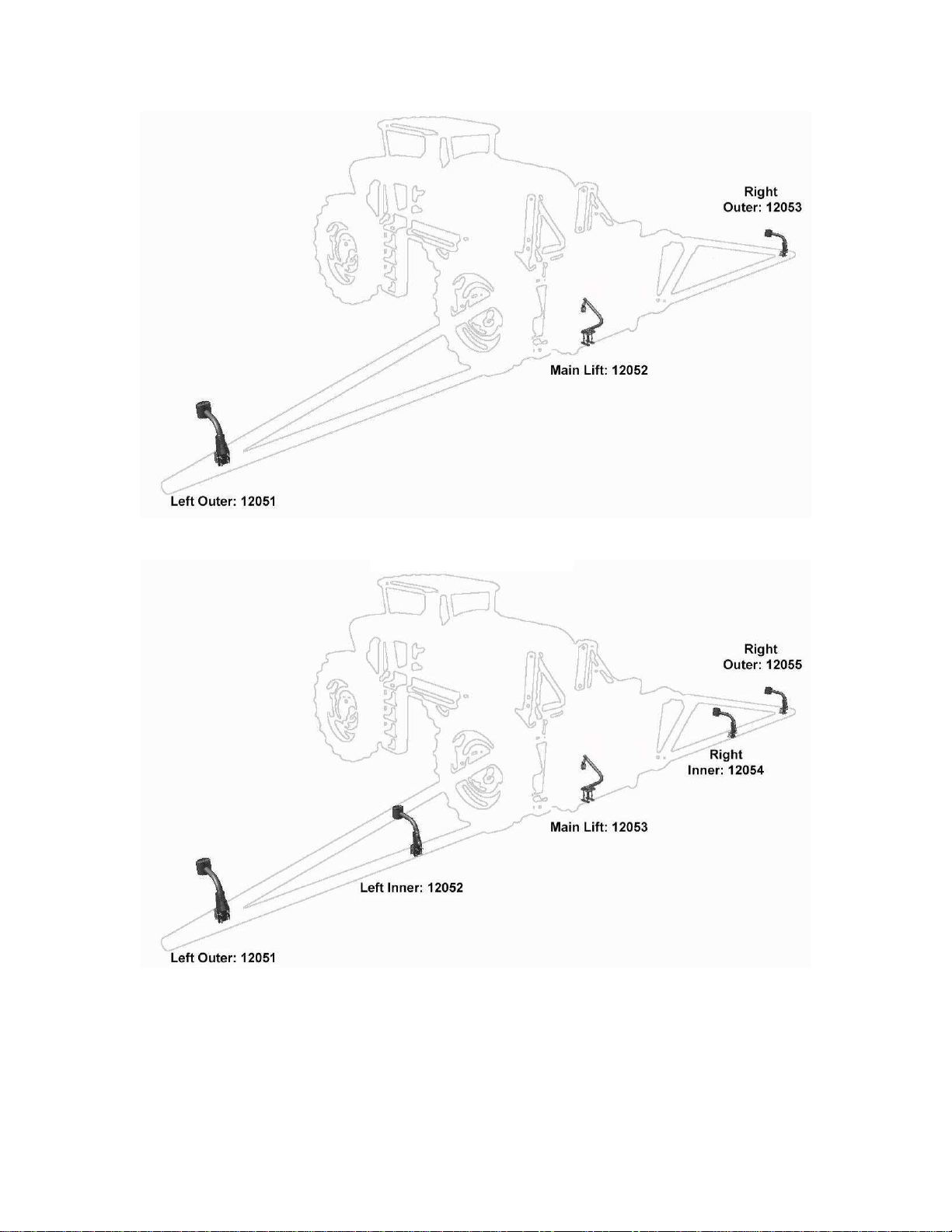
Figure 10 – Sensor Serial Number Installation Location
3 SENSOR SYSTEM
5 SENSOR SYSTEM

11
4.2 MAIN
LIFT
SENSOR
INSTALLATION
1. Assemble the main lift sensor bracket
(B11) as shown in Figure 11.
Figure 11 – Main Lift Sensor Bracket
2. The bracket can then be mounted to the
lowest frame member on the center
section of the sprayer. The bracket
should be mounted so the sensor
mounting collar is in approximately the
center of the sprayer and ahead of the
boom (Figure 12 and Figure 13).
The sensor mounting collar must
not be behind the sprayer’s wheel.
The General Mounting Rules for
UC4+ Ultrasonic Sensors, from the
previous section, must be followed.
Figure 12 – Main Lift Sensor Bracket
Mounting Position
3. Mount the sensor onto the sensor
mounting collar (Figure 12).
Figure 13 – Main Lift Sensor Mounted in
the Correct Location
A common mounting location for the main
lift sensor on a sprayer is shown in Figure
13Error! Reference source not found.. If
desired, the tube part of the bracket can be
cut to a shorter length.
Bracket Tube
Sensor
Mounting Tab
Sensor Mounting
Collar
Bracket Base
12
4.3 R
OLL
S
ENSOR
I
NSTALLATION
When mounting the roll sensors,
be sure they can not contact any
parts of the boom or frame.
Mount the roll sensors to the included
roll sensor brackets using the machine
screws and nylon lock nuts, as illustrated
in Figure 14.
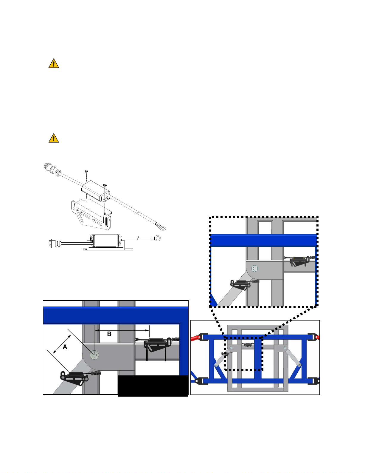
The roll sensors must be mounted
tightly to the brackets.
Figure 14 – Mounting the Roll Sensor to
the Roll Sensor Mounting Bracket
When mounting the roll sensors, use the
following guidelines and refer to Figure 15.
a) The smaller the distance between A
and Bin Figure 15, the better the
performance will be.
b) Ensure the roll sensors are sitting
relatively level when the sprayer
chassis and boom are level.
c) Both roll sensors must be mounted
with the circular AMP connector
facing towards the Right-Hand
Wing (when looking from the rear
of the sprayer).
Figure 15 – General Roll Sensor Mounting Location on a Trapeze Style Boom
Connectors towards
Right-hand Wing

13
4.3.1 Boom Frame Roll Sensor
Mounting
1. Use the supplied hardware to mount the
boom frame roll sensor (E04) as shown
in Figure 16.
When mounting the boom frame roll
sensor follow these guidelines:
a) To prevent bending the bracket,
ensure bolts are placed as close
together as possible (minimize Cin
Figure 16).
b) Be sure to use the roll sensor without
the temperature probe (E04).
c) When the boom is centered (not
rolled over) the roll sensor should be
level with respect to the sprayer
chassis.
d) It is best to mount the roll sensor to
the left hand trapeze link (when
looking from the rear of the sprayer).
e) The roll sensor AMP (circular)
connector MUST exit towards the
right had wing (when looking from
the rear of the sprayer).
Figure 16 – Boom Frame Roll Sensor
Mounted to a Trapeze Link
2. Cable-tie the sensor connector to the
frame with enough slack to allow the
link to rotate.
Make sure the bracket does not
collide with any parts of the
sprayer when the boom rotates.
Also ensure there is enough slack
to allow the roll sensor to rotate.

14
4.3.2 Chassis Roll Sensor Mounting
1. It is often best to cable tie the chassis
roll sensor in place. When mounting the
chassis roll sensor follow the guidelines
and refer to Figure 17.
The chassis roll sensor must be
mounted on a portion of the
sprayer that does not pivot and is
as close to the boom frame roll
sensor as possible (Figure 15).
a) Make sure you are using the roll sensor
with the temperature probe (E03).
b) Ensure the roll sensor is level with
respect to the chassis.
c) The AMP (circular) connector MUST
exit towards the right hand wing.
d) Make sure the temperature probe is
able to reach the side of the valve
block.
Figure 17 – Chassis Roll Sensor Mounting
2. Fasten the temperature probe to the
UC4+ valve block, using the supplied
3/8”x1/2” bolt as shown in Figure 18.
3. Cable-tie the temperature probe cable
and AMP (circular) connector securely
to a frame member.
Check that the roll sensors and
cables will not interfere with, or
come into contact with any parts of
the sprayer.
Figure 18 – Temperature Probe Attached
to the UC4+ Valve Block

15
4.4 H
YDRAULIC
I
NSTALLATION
WARNING!
The hydraulic system creates very high
pressure. Before disconnecting any
hydraulic lines ensure all pressure has
been bled from the system. When
changing the boom hydraulic hoses leave
the booms in TRANSPORT POSITION.
IMPORTANT:
Component failure due to oil
contamination is not covered under the
UC4+ Spray Height Control system
warranty. It is recommended that a
qualified technician does the hydraulic
installation.
4.4.1 Valve Assembly
1. On a clean surface remove all plastic
plugs from the NORAC hydraulic Valve
(V01) (Figure 19).
2. Install the 6MB-6MJ fittings (F07) on
the "P" and "T" ports and tighten to 18
ft-lbs.
Figure 19 – NORAC Valve Block
4. Install two orifices (F08) into the "B"
ports with the notch facing outward as
shown in Figure 20.
5. Install the remaining orifices (F08) into
the "A" ports with the notch facing
inward as shown in Figure 20.
6. Install the 6MB-4MJ fittings (F01) into
the "A" and "B" ports and tighten to 18
ft-lbs.
Figure 20 – Valve Block Assembly
4.4.2 Valve Mounting
1. Mount the NORAC valve (V01) on the
sprayer using the valve mounting
bracket (B10).
A common location for the valve
block is immediately to the right of
the sprayer’s valve block.
Figure 21 - Valve mounting location
NORAC
Valve

16
2. As shown in Figure 22, screw the short
side of the threaded rods into the bottom
of the valve block at least 3/8" (1 cm).
The valve mounting holes are drilled and
tapped 3/8 (1 cm) NC-1" (2.5 cm) deep.
3. Tighten the Hex nuts to hold the rods.
4. Put the mounting bracket on the other
side of the tube and tighten with the
spring washers and the Hex nuts.
5. Cut excess off of the rods, if necessary.
You must ensure no hydraulic
components will interfere with any
sprayer parts or be pulled tight at
any time.
Figure 22 – Valve Mounting Location
4.4.3 Hydraulic Plumbing
WARNING!
From this point in the installation the
booms will be inoperative until the
electronics are fully installed.
1. After the NORAC valves are mounted,
the hydraulic hoses and fittings can be
plumbed. The plumbing for the
hydraulic circuit is shown schematically
in Figure 3.
2. Connect the NORAC supplied hoses
(H01) to the Pressure (P) and Tank (T)
ports on the NORAC valve block (V01).
3. Remove the plugs from the spare
Pressure and Tank ports on the PLA
valve block.
4. Insert the 6MJ-8MB fittings (F03) into
the spare P and T ports on the PLA valve
block.
5. Connect hoses H01 (P and T lines), into
the ports on the sprayer valve block
where the 6MJ-6MB (F03) fittings are
located.
6. The existing hoses that run to the boom
tilt cylinders should be disconnected
from the sprayer valve block and
reconnected to the NORAC valve block.
7. The “raise” lines must be connected to
the "B" ports of the NORAC valve
block. The ports on the sprayer block
must then be capped with 4FJCN caps
(F02).
8. The "A" ports of the NORAC block
must be connected to the “lower” lines
of the cylinders. The ports on the sprayer
block must then be capped with F02.
It may be necessary to use the
supplied extension hoses (H02) and
4MJ-4MJ fittings (F04) to extend
the left tilt cylinder hoses.

17
ROP
4.5 E
LECTRICAL
I
NSTALLATION
1. Install the UC4+ Control Panel (E01) in
the cab of the sprayer. Mount the panel
where it will be clearly visible and
within easy reach of the operator.
A good spot to mount the UC4+ control
panel is on the right hand side of the cab
to the Roll Over Protection Bar. Four
pilot holes for the screws provided need
to be drilled to facilitate the control
panel mounting.
An alternate mounting bracket is
available from PLA. Figure 24 is an
example using the PLA mounting
bracket.
Figure 23 – Control Panel Mounting
Figure 24 – PLA Control Panel Mounting
ROP

18
Figure 25 – Cable Configurations: C10, C1 and C4
2. Connect the UC4+ power cable (C10) to
the UC4+ control panel in the sprayer
cab. Ensure both plugs (P16 and P4) are
connected to the panel.
3. Connect the 3-pin AMP plug (P3) on
C10 to the 3-pin AMP receptacle (R3)
on the power pigtail interface cable
(C14).
Ensure the UC4 control panel’s
power is OFF for the remaining
installation (Bottom of switch
pressed IN). Use caution when
handling the 12 V power line of the
existing wiring.
4. Connect the free ends of C14 to the
power and ground terminals in the PLA
fuse panel. The fuse panel is located
behind the sprayer’s seat.
5. Route the receptacle end (R16) of C10
out of the cab.
6. Connect the 16-pin AMP plug (P16) of
the valve extension cable (C11) to R16
of C10 on the outside of the cab (Figure
25).
Other manuals for UC4+
41
Table of contents
Other Norac Farm Equipment manuals

Norac
Norac UC4+ User manual

Norac
Norac UCB Sx275 User manual

Norac
Norac UC5 Topcon X30 User manual

Norac
Norac UC4 Total Control User manual

Norac
Norac UC4.5 User manual

Norac
Norac UC4.5 User manual

Norac
Norac UC5 Topcon X30 User manual

Norac
Norac UC5 Topcon X30 User manual

Norac
Norac UC4+ User manual

Norac
Norac UC5 Sx275 User manual
Popular Farm Equipment manuals by other brands


Kemper
Kemper 300F Operator's manual

Ritchie
Ritchie CattleMaster Series installation instructions

Walinga
Walinga Grain-Vac 7614F Operator's manual

Zipper Mowers
Zipper Mowers ZI-MD500HST user manual

Amazone
Amazone Cirrus-Control Brief instructions

GREAT PLAINS
GREAT PLAINS Turbo Max VT1110-7.5M Operator's manual