Norac UC5 Topcon X30 User manual

UC5 Active Roll ControlTM
Rogator (2012+)
Installation Manual
5467BC-RG1

Printed in Canada
Copyright 2012 by NORAC Systems International Inc.
Reorder P/N: 5467BC-RG1-INST Rev D (UC5 Active Roll Control - Rogator (2012+))
NOTICE: NORAC Systems International Inc. reserves the right to improve products and their specifications without notice and
without the requirement to update products sold previously. Every effort has been made to ensure the accuracy of the information
contained in this manual. The technical information in this manual was reviewed at the time of approval for publication.

Contents
1Introduction................................................................................................................ 1
2Technical Specifications ............................................................................................ 2
3General UC5 System Layout.................................................................................... 3
4Kit Parts ...................................................................................................................... 4
5Linear Roll Cylinder Installation............................................................................... 8
6Hydraulic Installation .............................................................................................. 13
7Electrical Installation ............................................................................................... 16
8Software Setup......................................................................................................... 18
9Cable Drawings ........................................................................................................ 19

1
1Introduction
Congratulations on your purchase of the NORAC UC5 Spray Height Control System. This
system is manufactured with top quality components and is engineered using the latest
technology to provide operating reliability unmatched for years to come.
When properly used the system can provide protection from sprayer boom damage, improve
sprayer efficiency, and ensure chemicals are applied correctly.
Please take the time to read this manual completely before attempting to install the system. A
thorough understanding of this manual will ensure that you receive the maximum benefit from
the system.
Your input can help make us better! If you find issues or have suggestions regarding the parts
list or the installation procedure, please don’t hesitate to contact us.
AGCO armrest version must be 1.0.0.120302.1100 (Update 90).
Every effort has been made to ensure the accuracy of the information contained in
this manual. All parts supplied are selected to specially fit the sprayer to facilitate
a complete installation. However, NORAC cannot guarantee all parts fit as
intended due to the variations of the sprayer by the manufacturer.
Please read this manual in its entirety before attempting installation.

2
2Technical Specifications
CAN ICES-3(A)/NMB-3(A)
This device complies with part 15 of the FCC Rules. Operation is subject to the following two
conditions: (1) This device may not cause harmful interference, and (2) this device must accept
any interference received, including interference that may cause undesired operation.
This equipment has been tested and found to comply with the limits for a Class A digital device,
pursuant to part 15 of the FCC Rules. These limits are designed to provide reasonable
protection against harmful interference when the equipment is operated in a commercial
environment. This equipment generates, uses, and can radiate radio frequency energy and, if not
installed and used in accordance with the instruction manual, may cause harmful interference to
radio communications. Operation of this equipment in a residential area is likely to cause
harmful interference in which case the user will be required to correct the interference at their
own expense.
This Class A digital apparatus complies with Canadian ICES-003.
Pursuant to EMC Directive – Article 9, this product is not intended for residential use.
Table 1: System Specifications
Supply Voltage (rated)
12VDC
Supply Current (rated)
10
A
Hydraulic Pressure (maximum)
3300 psi
Baud Rate 250 kbps
Clock Frequency (maximum)
96 MHz
Solenoid Valve P
W
M Frequency
300 Hz
Ultrasonic Sensor Transmit Frequency
50 kHz
Operating Temperature Range
0°C to 80°C

3
3General UC5 System Layout
Figure 1 illustrates the general layout of the UC5 Rogator active roll system components.
Many of these components should already be installed on the sprayer.
Figure 1: General UC5 Rogator Active Roll System Layout

4
4Kit Parts
4.1 Kit Overview
Figure 2: UC5 Rogator Active Roll Control Parts

5
4.2 Hydraulic Plumbing
Figure 3: UC5 Rogator Active Roll Control Hydraulic Plumbing
Only the components shown in black are included in this kit.

6
4.3 List of Parts
This kit is to be used when installing the Active Roll Control option with existing 2012+
Rogator installations.
Item Part Number Name Quantity
C01 43220-01 CABLE UC5 NETWORK 14 AWG 1M 1
C10 43230-04 CABLE UC5 VALVE 2PIN DT TO 2PIN DT 2
E05 43750 UC5 ULTRASONIC SENSOR 1
E12 43764 UC5 NETWORK COUPLER 2-WAY 1
H01 44864-03 HOSE ASSEMBLY 122R2-08 166 IN L 6FORX 6FORX 2
H10 44865-65 HYDRAULICS FITTING KIT - RG12 1
H20 44752-111 LINEAR ROLL CYLINDER 8IN LT 1
H21 44750-10 HARDWARE MOUNTING LINEAR ROLL - ROGATOR UPPER 1
H22 44750-11 HARDWARE MOUNTING LINEAR ROLL - ROGATOR LOWER 1
M02 5467BC-RG1-INST MANUAL INSTALLATION UC5 ACTIVE ROLL CONTROL KIT - ROGATOR (2012+) 1
P03 106162 UC5 NETWORK 6 PIN PLUG MOLDED 1
V70 44962D VALVE ASSEMBLY EXPANSION DPOC PROP DT 4 BOLT 1

7
4.4 Hydraulic Fittings Kit Details (P/N: 44865-65)
Item Part Number Name Quantity
Picture
F07 44917 MALE TO MALE ADAPTER - 6MB 6MOR 4
F09 44975 ORIFICE INSERT .036 IN ONE WAY 1
F17 44927 ORIFICE INSERT .031 IN ONE WAY 1
F18 104590 90 DEGREE ADAPTER - 6MOR 6FORX90 2
6 M B - 6 M OR X 90
SIZE IN
1/16TH'S
GENDER: MALE
OR FEMALE
90° ANGLE
SWIVEL
TYPE
GENDER
SIZE
TYPE:
B - ORB
J - JIC
OR - FLAT
FACE
P - PIPE
Fitting Name
Example:
Do not use high speed power tools/drills when installing hardware.
The use of dielectric grease is not recommended on any NORAC electrical
connections.
To ensure all stainless steel hardware does not gall or seize apply a light coating of
the supplied Permatex Anti-seize grease to all threaded parts upon installation.
Permatex Anti-seize lubricant is preferred, but other similar anti-seize products
may be used.

8
5Linear Roll Cylinder Installation
It is very important that the existing roll sensors (E04) are removed from the
sprayer prior to installation.
Before continuing, tilt both the left and right booms up to the top of their stroke to
make it easier to rotate the boom.
5.1 Installation for Sprayers with Rogator Springs and Dampers
If the boom is an early 2012 120’ production model, the linear damper mounting brackets may
not have been installed at the factory. These brackets are on the left side of the boom as
shown in Figure 5. The following mounting brackets are needed:
Part Number Name Quantity
44750-1 BRACKET MOUNTING LINEAR ROLL ROGATOR LT - UPPER 1
44750-2 BRACKET MOUNTING LINEAR ROLL ROGATOR LT - LOWER 1
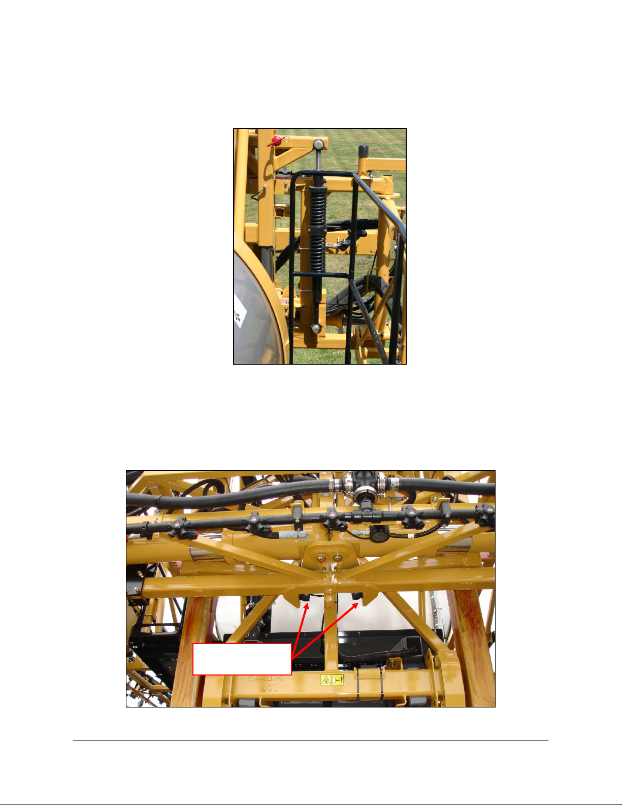
1. Before installing the linear roll cylinder, the factory springs and dampers must be removed
from the sprayer. The springs and dampers to be removed are shown in Figure 4. If the
sprayer does not have springs and dampers as shown in Figure 4, proceed to Section 5.2.
Figure 4: AGCO Factory Spring and Damper
9
5.2 Installation for Sprayers with a NORAC Linear Damper
1. Remove the linear damper from the mounting brackets.
Figure 5: Linear Damper Mounting Location
5.3 Both Installations
1. The rubber bumpers must be removed from the sprayer (120’ booms only). The rubber
bumper location is shown in Figure 6.
Figure 6: Rubber Bumper Location
Rubber Bumpers to
be Removed (x2)
10
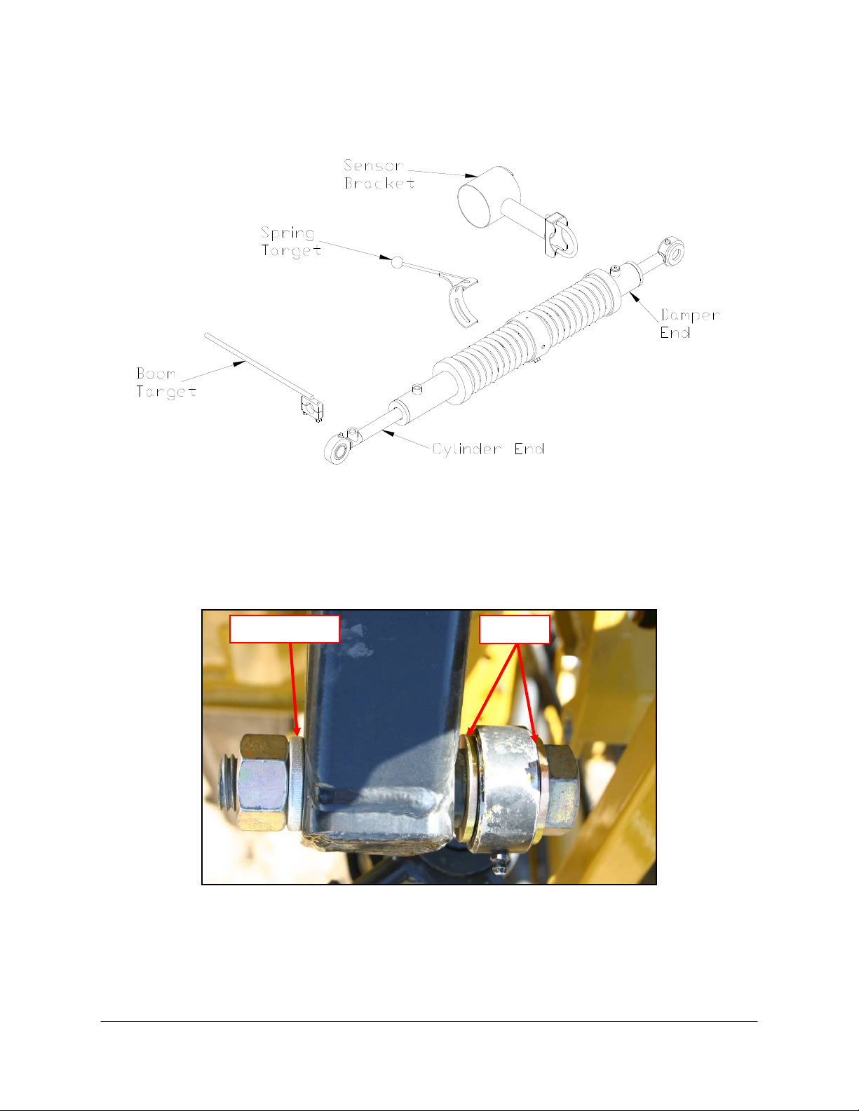
2. In the linear roll cylinder crate is the linear roll cylinder, boom target, spring target and
sensor bracket.
Figure 7: Linear Roll Cylinder Assembly
3. Using the supplied 1 inch bolt and two spacers, install the damper end of the linear roll
cylinder onto the top mounting bracket. There must be a spacer on each side of the
spherical bearing. The damper should be mounted on the back side of the mount (between
the mount and boom).
Figure 8: Linear Roll Cylinder Top Mount (Top View)
Spring Washe
r
Spacers
11
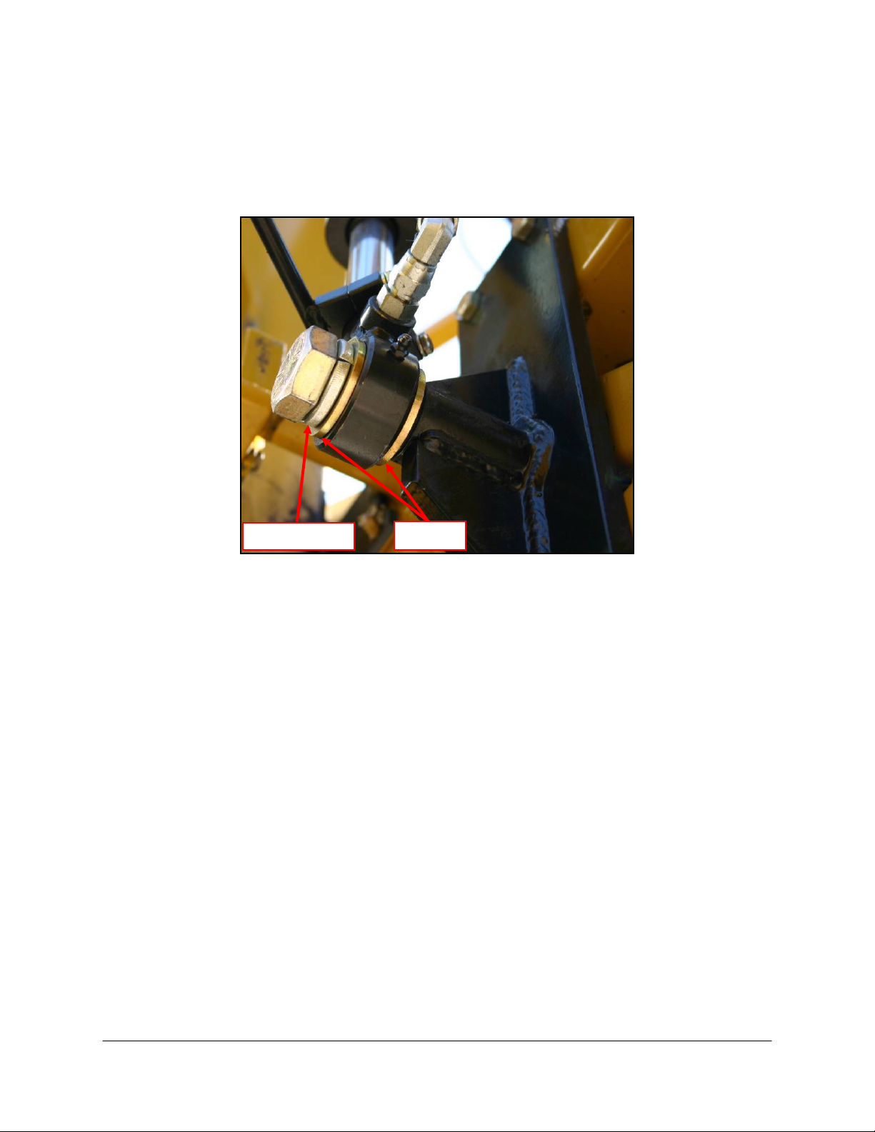
4. Using the other 1 inch bolt and spacers, attach the damper end (end with only one port) of
the linear roll cylinder to the bottom mount. Be careful not to move the shaft of the
cylinder because doing so will push oil out and suck air in.
5. Tighten both the top and bottom linear roll cylinder mounting bolts to 500 ft-lbs.
Figure 9: Bottom Linear Roll Cylinder Mount
6. Install the spring target and align by rotating the metal casing around the linear roll cylinder.
7. Install the sensor onto the sensor mounting bracket.
8. Mount the sensor bracket to the damper end (the end with no hoses). A straight edge can
be used to line up the spring target with the center of the hole on the sensor mounting
bracket. The mount should be facing as far forward as possible, but be sure it will not
contact the catwalk when the boom is raised to the top.
9. Mount the boom target to the cylinder end (the end with hoses).
10. Align the cylinder target (bottom rod) so that it is 5/8” to the side of the spring target
(Figure 10).
Spring Washe
r
Spacers

12
Figure 10: Linear Roll Cylinder Target Alignment
Top View
Side View
Sensor
Mount
Spring
Target
Cylinder
Target

13
6Hydraulic Installation
Ensure all pressure has been bled from the system before disconnecting any lines
or fittings. Hydraulic pressure will exist on the wing tilt circuits unless the wings
are being supported by other means. The hydraulic installation may be performed
with the wings in transport position, resting on the ground or with the tilt cylinders
fully extended.
Component failure due to oil contamination is not covered under the NORAC UC5
system warranty. It is recommended that a qualified technician perform the
hydraulic installation.
6.1 Valve Assembly
1. On a clean surface remove all plastic plugs from the block.
2. Install the orifice (F09) into the “A” port of the expansion block with the notch facing in.
3. Install the orifice (F17) into the “B” port of the expansion block with the notch facing in.
4. Install the 6MB-6MOR (F07) fittings into the “A” and “B” ports of the expansion block.
Tighten to 18 ft-lbs (24 Nm).
Figure 11: Expansion Block Orifice Orientation

14
6.2 Expansion Block Assembly
1. Loosen the existing 2-station valve block so that it can be moved and/or twisted for the
installation of the expansion block.
2. Remove the four 4MBP plugs from the side of the 2 station valve block.
3. Coat the four o-rings in hydraulic oil and install them into the expansion block. Ensure the
o-rings are seated properly.
4. Attach the expansion block to the 2 station block using the included spring washers and
bolts.
5. Tighten the bolts to 31 ft-lbs.
Figure 12: NORAC Expansion Block Assembly

15
6.3 Hydraulic Plumbing
From this point on in the installation the booms will be inoperative until the
hydraulics are fully installed.
1. After the NORAC valve is mounted, the hydraulic hoses and fittings can be plumbed. The
plumbing for the hydraulic circuit is shown schematically in Figure 3.
2. Connect hoses H01 to the “A” and “B” ports of the expansion block and route to the roll
cylinder.
3. Connect the hose from the “A” port to the port on the rod end of the cylinder using a
6MOR-6FORX90 (F18) fitting and a 6MB-6MOR (F07) fitting.
4. Connect the hose from the “B” port to the port on the barrel of the cylinder using a
6MOR-6FORX90 (F18) fitting and a 6MB-6MOR (F07) fitting.

16
7Electrical Installation
1. Locate the valve module installed on the NORAC valve block. Remove the plugs installed
in positions 7 and 8.
2. Connect the 2 pin connector on cables C10 into positions 7 and 8 on the valve module.
Connect the other end of cables C10 to the 2 pin connectors on the NORAC expansion
block (V70).
3. Disconnect and remove the two NORAC roll sensors (small rectangular box with a cable
running from it). One roll sensor is installed on the chassis and one on the boom. See
Figure 13 for locations.
Figure 13: Roll Sensor Locations (Viewed from the rear of sprayer)
Boom Frame
Chassis

17
4. Connect the active roll sensor (E05) where one of the roll sensors was connected using
cable C04 and a 2-way coupler (E12). Plug the unused connector where the second roll
sensor was connected using the 6-pin plug.
Figure 14: Valve Module Connections
Figure 15: Electrical Installation
Only the components shown in black are included in this kit.
Output Numbe
r
Normal Function
1
Left Up
2
Left Down
3
Right Up
4
Right Down
5
Option 1
6
Option 2
7
Roll CW
8
Roll CCW
Other manuals for UC5 Topcon X30
55
Table of contents
Other Norac Paint Sprayer manuals

Norac
Norac UC5 Topcon X30 User manual

Norac
Norac UC4.5 User manual

Norac
Norac UC5 Topcon X30 User manual

Norac
Norac UC4.5 User manual

Norac
Norac UC4 Total Control User manual

Norac
Norac UC5 Topcon X30 User manual

Norac
Norac UC4.5 User manual

Norac
Norac UC4.5 User manual

Norac
Norac UC5 Topcon X30 User manual

Norac
Norac UC4.5 User manual

Norac
Norac UC4.5 User manual

Norac
Norac UC5 Topcon X30 User manual

Norac
Norac UC5 Topcon X30 User manual

Norac
Norac UC 4.5 Hagie STS10 User manual

Norac
Norac UC5 Topcon X30 User manual

Norac
Norac UC4+ User manual

Norac
Norac UC5 Topcon X30 User manual

Norac
Norac UC4.5 User manual

Norac
Norac UC4.5 User manual

Norac
Norac UC4.5 User manual


