Norac UC4+ User manual

Variable Geometry - Europe
Installation Manual
Spray Height Controller
Improving the competitiveness of Industry and Agriculture
throu
g
h Precision Measurement

Printed in Canada
Copyright 2005-08 by NORAC Systems International Inc.
Reorder P/N: UC4+BC+EU1-INST Rev A (Variable Geometry - Europe)
NOTICE
NORAC Systems International Inc. reserves the right to improve products and their specifications without notice and without the requirement to
update products sold previously. Every effort has been made to ensure the accuracy of the information contained in this manual. The technical
information in this manual was reviewed at the time of approval for publication.

TABLE OF CONTENTS
1INTRODUCTION ................................................................................................................................. 1
2GENERAL SYSTEM DESCRIPTION .................................................................................................. 2
3PARTS LISTS......................................................................................................................................... 3
4INSTALLATION PROCEDURE.......................................................................................................... 6
4.1DETERMINING THE STYLE OF INSTALLATION................................................................................. 6
4.1.1Electrically Teed Installation...................................................................................................................................................... 6
4.1.2Hydraulically Teed Installation ................................................................................................................................................. 8
4.2WING SENSOR INSTALLATION ..................................................................................................... 10
4.3MAIN LIFT SENSOR INSTALLATION .............................................................................................. 13
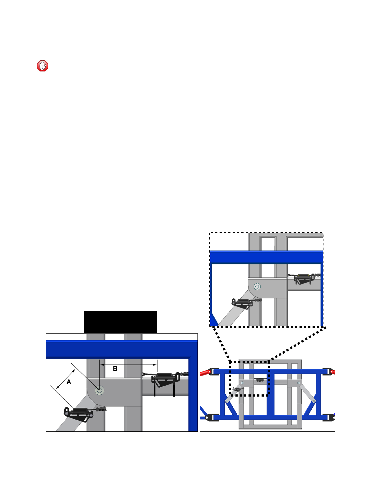
4.4ROLL SENSOR INSTALLATION....................................................................................................... 14
4.4.1Trapeze Style Roll Sensor Installation..................................................................................................................................15
4.4.2Center Pivot Style boom Roll Sensor Installation...............................................................................................................18
4.4.3Inverted Roll Sensor Mounting...............................................................................................................................................20
4.4.4Temperature Probe...................................................................................................................................................................20
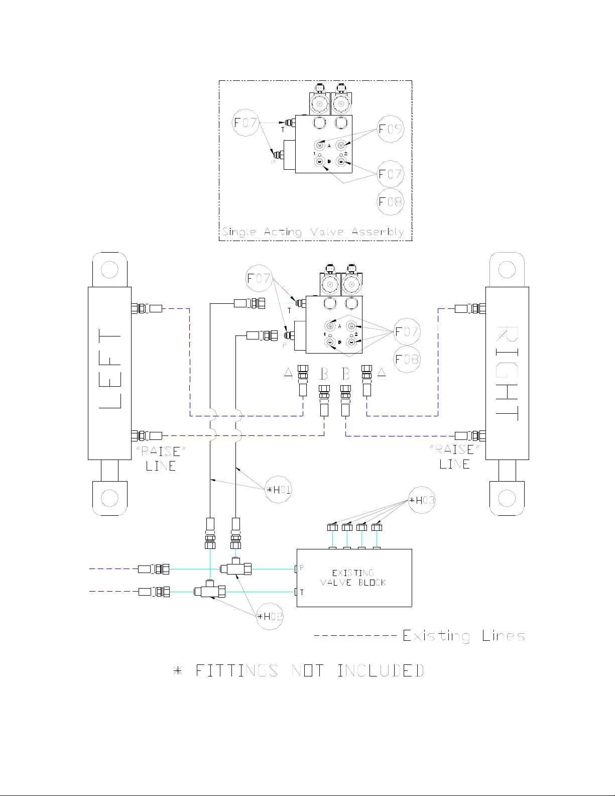
4.5HYDRAULIC INSTALLATION.......................................................................................................... 21
4.5.1Valve Assembly...........................................................................................................................................................................21
4.5.2Valve Mounting ..........................................................................................................................................................................23
4.5.3Hydraulic Plumbing ...................................................................................................................................................................24
4.6ELECTRICAL INSTALLATION ......................................................................................................... 25
4.6.1Electrical Installation: Electrically Teed...............................................................................................................................27
4.6.2Electrical Installation: Hydraulically Teed ..........................................................................................................................29
4.6.3Finishing the Electrical Installation ........................................................................................................................................30
4.7COMPLETING THE INSTALLATION ................................................................................................ 31
5CALIBRATING THE SLANT VALVE............................................................................................... 32
5.1OVERVIEW .................................................................................................................................... 32
5.2VALVE DEADZONE TEST .............................................................................................................. 33
5.3VALVE GAIN TEST ........................................................................................................................ 34
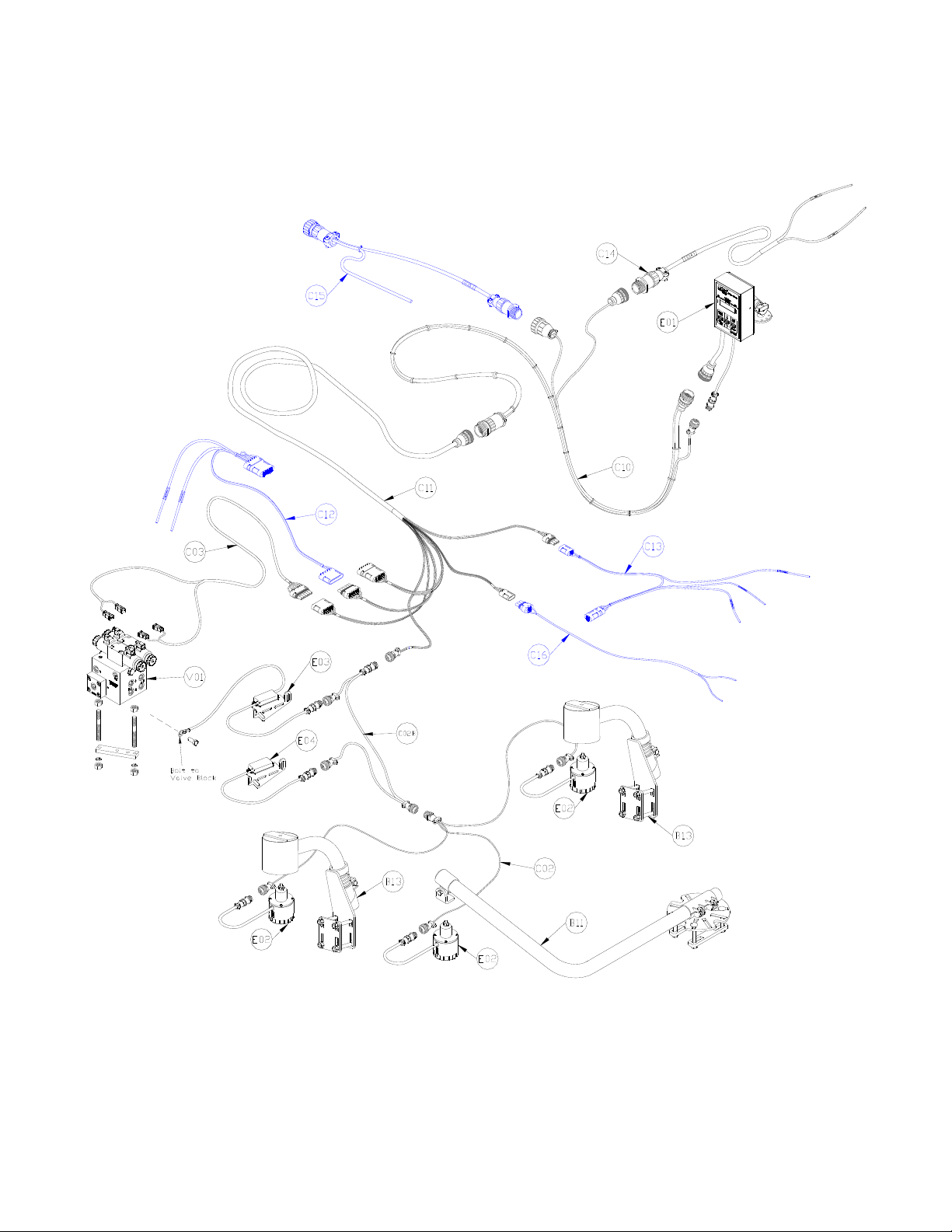
6ELECTRICAL REFERENCE – CABLE DRAWINGS....................................................................... 35
6.1ITEM C02: 44668 –SENSOR BRANCH CABLE ............................................................................... 35
6.2ITEM C02B: 44664 –CABLE UC4 CAN NODE DUAL.................................................................. 35
6.3ITEM C3: 44656D –CABLE VALVE VARIABLE RATE DT .............................................................. 36
6.4ITEM C10: 44650-35 –CABLE POWER GENERIC PULL-TYPE ....................................................... 37
6.5ITEM C11: 44651-03 –CABLE EXTENSION CABLE VALVE GENERIC ............................................ 38
6.6ITEM C14: 44658-28 –CABLE INTERFACE UC4 BC C14 POWER PIGTAIL .................................. 39

1
1 INTRODUCTION
Congratulations on your purchase of the NORAC UC4+ Spray Height Controller. This system is
manufactured with top quality components and is engineered using the latest technology to provide
operating features and reliability unmatched for years to come.
When properly used the system can provide protection from sprayer boom damage, improve sprayer
efficiency, and ensure chemicals are applied correctly.
Please take the time to read this manual completely before attempting to install the system. A thorough
understanding of this manual will ensure that you receive the maximum benefit from the system.
YOUR INPUT CAN HELP MAKE US BETTER! If you find issues or have suggestions
regarding the parts list or the installation procedure, please don’t hesitate to contact us.

2
2 GENERAL SYSTEM DESCRIPTION
Figure 1 depicts the general system layout of the UC4+ Spray Height Control system.
Figure 1 – System Components and General Location
NOTICE:
Every effort has been made to ensure the
accuracy of the information contained in this
manual. All parts supplied are selected specially
to fit the sprayer to facilitate a complete
installation. However, NORAC cannot
guarantee all parts fit as intended due to the
variations of the sprayer by the manufacturer.
Please read this manual in its entirety
before attempting installation.
ATTENTION:
When installing the UC4+ Spray Height Control
system please be aware that at a point in the
installation your sprayer booms will be
inoperative until the installation is complete.
Any installation procedure requiring
boom movement will need to be done
first. Once the hydraulics have been
disconnected you must complete the electrical
installation before the booms become operative.

3
3 PARTS LISTS
The parts that come with your UC4+ Sprayer Boom System are listed in Table 1. The item number on
the left side of this table references each part.
Please ensure that all parts in your kit are present before proceeding with your installation.
Table 1 – UC4+ Spray Height Control system Parts
Item Part Number Name Quantity
B05 44706-01 KIT CABLE TIE BLACK 10 PCS 21 IN 150 PCS 7.5 IN 1
B10 44700-06 BRACKET VALVE MOUNTING STD 1
B11 44743 MOUNTING BRACKET MAIN LIFT SENSOR UC4 PLUS 1
B13 44728 MOUNTING BRACKET COMPLETE UC4 BREAKAWAY EXTENDED 2
C02 44668 CABLE UC3 SENSOR BRANCH 1 AMP RECEPT 3 AMP PLUG BC 1
C02B 44664 CABLE UC4 CAN NODE DUAL 1
C03 44656D CABLE VALVE VARIABLE RATE DT 1
C10 44650-35 CABLE POWER GENERIC PULL-TYPE 1
C11 44651-03 CABLE EXTENSION VALVE GENERIC 1
C14 44658-28 CABLE INTERFACE UC4 BC C14 POWER PIGTAIL 1
E01 4461BC+ UC4 PLUS BOOM CONTROL PANEL 1
E02 44631 UC4 ULTRASOUND SENSOR 3
E03 45000* UC4 PLUS ROLL SENSOR W TEMPERATURE PROBE VER. 2 1
E04 45001* UC4 PLUS ROLL SENSOR VER. 2 1
H20 44865-34 HYDRAULICS FITTING KIT - GN1 1
M01 446BC+MAN7 OPERATOR MANUAL UC4+ SPRAY HEIGHT CONTROL 1
M10 UC4+BC+EU1-INST MANUAL INSTALLATION UC4+ GENERIC VARIABLE GEOMETRY - EUROPE 1
V01 44963D VALVE BLOCK ASSEMBLY 2 STATION CC/LS PROP DT 4 BOLT 1
* For systems purchased BEFORE October 1, 2011, the roll sensor part numbers are 44641 and 44642.

4
Table 2 – 44865-34 - Hydraulics Fittings Kit Details
Item Part Number Name Quantity
Picture
F07 103312 MALE ADAPTER - 6MB 6MJ 6
F08 44928 ORIFICE INSERT .047 IN ONE WAY 4
F09 104369 PLUG - 6MBP 2
6 M B - 6 M OR X 90
SIZE IN
1/16TH'S
GENDER: MALE
OR FEMALE
90° ANGLE
SWIVEL
TYPE
GENDER
SIZE
TYPE:
B - ORB
J - JIC
OR - FLAT
FACE
P - PIPE
Fitting Name
Example:
The use of dielectric grease is not recommended on any NORAC electrical connections.
To ensure all stainless steel hardware does not gall or seize apply a light coating of the
supplied Permatex Anti-seize grease to all threaded parts upon installation. Permatex
Anti-seize lubricant is preferred, but other similar anti-seize products may be used.

5
Generic interface cables are shown in this manual. They are available separately from
NORAC. Please see UC4+BC+CBL, UC4+ Generic Cable Ordering Guide, for more
information.
Figure 2 – UC4+ Spray Height Control Kit Components
* Items shown in blue are not included in kit.
* Interface cables (C12, C13, C15, C16, C17 & C18) are NOT included, but may be
required. Order separately, referring to NORAC Generic Cable Ordering Guide.

6
4 INSTALLATION PROCEDURE
4.1 DETERMINING THE STYLE OF
INSTALLATION
This install may require additional
electrical/hydraulic components.
Do NOT proceed with install until
all parts are available.
In general, there are two styles of installation
that can be done with the NORAC UC4+ Spray
Height Control system: Electrically Teed
Installation and Hydraulically Teed Installation.
4.1.1 Electrically Teed Installation
Electrically Teed Installation is the preferred
style of installation. However, this style can
be done only if the sprayer valve block has
individual electrical wiring to control each
boom function (e.g. left up, left down, right
up, right down, main up, and main down).
Figure 3 and Figure 4 show the
Electrically Teed installation in its
general installation configuration.
Figure 3 – Electrical Wiring Applicable for Electrically Teed Installation

7
Figure 4 – Hydraulic Components: Electrically Teed Installations

8
4.1.2 Hydraulically Teed Installation
Hydraulically Teed Installation must be done
if the sprayer valve block does NOT have
individual electrical wiring to control each
boom function. For example, your sprayer
may have signal lines to select a boom (left,
right and main) and separate electrical signals
for the direction (up and down).
For Hydraulically Teed Installation,
MANUAL mode of the UC4+ Control
System does not operate the same as with
Electrically Teed Installation. Electrically
Teed Installation will allow the operator to
trigger individual boom movements into
MANUAL mode while maintaining AUTO
mode for the other boom movements (e.g.
left boom can be in MANUAL mode while
right boom is still in AUTO mode).
Hydraulically Teed Installation does not
support this function. If the operator
triggers any boom movement, the whole
NORAC system will convert to MANUAL
mode.
Hydraulically Teed Installation may
also be done if the operator wants
the existing sprayer valves, instead
of the NORAC valves, to operate
the booms when the NORAC
system is in MANUAL mode.
Figure 5 and Figure 6 show the
Hydraulically Teed Installation in its
general installation configuration.
Figure 5 – Typical Electrical Wiring for which Hydraulically Teed Installation is Required

9
Figure 6 – Hydraulic Components: Hydraulically Teed Installation

10
4.2 WING SENSOR INSTALLATION
1. Assemble the Breakaway Sensor Mounting
Brackets (B11) as show in Figure 7 and
Figure 8.
Figure 7 – Breakaway Sensor Bracket
Exploded View
Figure 8 – Breakaway Sensor Mounting
Bracket Assembly
To assemble the breakaway sensor bracket:
a) Assemble the bolt and nut into the
collar.
b) Grease the bottom edge of the collar
and the angled tube of the base.
c) Place the collar onto the angled tube of
the mounting base.
d) Install the spring between the collar and
the upper ring of the base.
e) Insert tube through assembly and tighten
the collar
2. Mount the sensor bracket onto the boom.
If possible, mount the sensor
brackets while the booms are in
their folded position to ensure that
they will not interfere with anything
when the boom is folded for
transport.
3. The sensor mounting brackets can be
installed with the mounting base behind
(Figure 11) or in front of the tube (Figure
9).
Mounting the sensor bracket to the
break-away section of the boom
may cause the boom to drop
suddenly as a break-away occurs.
This will occur on break-away
sections which lift as they break
away.
For optimal boom tip protection, it
is recommended that the sensor be
mounted within approximately two
feet (60cm) of the boom tip.
Please refer to the UC4+ Spray Height
Control system warranty at the end of the
UC4+ Spray Height Control
Operator’s Manual (M01) for
implications.
4. Mount the NORAC UC4+ ultrasonic sensor
(E02) into the sensor brackets. The sensors
should be oriented forward (ahead) of the
boom (see Figure 9 and Figure 11).

11
When installing the UC4+ sensors
(E02), start with the smallest serial
number on the left hand side
proceeding to the largest serial
number on the right hand side
(Figure 12).
5. Sensor cables should run through the
mounting bracket tube and then behind the
member the bracket is mounted onto.
Cable-tie the connector in place. The cable
must not be allowed to hang below the
boom (Figure 9).
Figure 9 – Another Acceptable Mounting
Avoid mounting sensors in
locations where they may read
from parts of the boom as shown in
Figure 10.
Figure 10 – Poor Mounting
(Sensor reading off Boom)
General mounting rules for UC4+
ultrasonic wing sensors:
a) In its lowest position, the sensor mouth
must be 9 inches or more from the
ground.
b) The bottom of the sensor must be at
least 9 inches in front of the spray
nozzles.
c) The bottom of the sensor must be at
least 9 inches above the spray nozzles.
d) Ensure that there are no obstructions
within a 12-inch diameter circle
projected directly below the center of
the sensor.
e) The sensor should be approximately
vertical at normal operating heights.
Figure 11 – Sensor Mounting Guidelines
A
B
B
D
C
Ultrasonic
Acoustic Cone

12
Apply a light coating of the supplied Permatex Anti-seize grease to all threaded parts upon
installation.
Figure 12 – Sensor Serial Number Installation Location
3 SENSOR SYSTEM
5 SENSOR SYSTEM

13
4.3 MAIN LIFT SENSOR INSTALLATION
1. Assemble the main lift sensor bracket (B11)
as shown in Figure 13.
Figure 13 – Main Lift Sensor Bracket
2. The bracket can then be mounted to the
lowest frame member on the center section
of the sprayer. The bracket should be
mounted so the sensor mounting collar is in
approximately the center of the sprayer and
ahead of the boom (Figure 14 and Figure
15).
The sensor mounting collar must
not be behind the sprayer’s wheel.
The General Mounting Rules for
UC4+ Ultrasonic Sensors, from the
previous section, must be followed.
Figure 14 – Main Lift Sensor Bracket
Mounting Position
3. Mount the sensor onto the sensor
mounting collar (Figure 14).
Figure 15 – Main Lift Sensor Mounted in
the Correct Location
Bracket Tube
Sensor
Mounting Tab
Sensor Mounting
Colla
r
Bracket Base

14
4.4 ROLL SENSOR INSTALLATION
Mount the roll sensors to the included roll
sensor brackets using the machine screws
and nylon lock nuts, as illustrated in Figure
16.
The roll sensors must be mounted
tightly to the brackets.
If your sprayer is a trapeze style
pivoting boom (the boom hangs
from two link arms) then follow
Section 4.4.1 to install the roll
sensors.
If your sprayer is a center pin
pivoting boom (the boom pivots on
a pin in the center of the boom)
then follow Section 4.4.2 to install
the roll sensors.
Sometimes it best to mount the
roll sensors in an inverted
orientation (upside down). For this
type of mounting refer to Section
4.4.3.
Figure 16 – Mounting the Roll Sensor to
the Roll Sensor Mounting Bracket

15
4.4.1 Trapeze Style Roll Sensor Installation
This section is only for trapeze style
booms (booms that hang from link
arms. If your sprayer has a center
pivot boom proceed to Section
4.4.2.
When mounting the roll sensors, use the
following guidelines and refer to Figure 17.
a) The smaller the distance between Aand
Bin Figure 16, the better the
performance will be.
b) Ensure the roll sensors are sitting
relatively level when the sprayer chassis
and booms are level.
c) Both roll sensors must be mounted with
the circular AMP connector facing
towards the Right-Hand Wing (when
looking from the rear of the sprayer).
Figure 17 – General Roll Sensor Mounting Location on a Trapeze Style Boom
Connectors towards
Right-hand Wing

16
4.4.1.1 Boom Frame Roll Sensor Mounting
1. Use the supplied hardware to mount the
boom frame roll sensor (E04) as shown in
Figure 18.
When mounting the boom frame roll sensor
follow these guidelines:
a) To prevent bending the bracket, ensure
bolts are placed as close together as
possible (minimize Cin Figure 18).
b) Be sure to use the roll sensor without
the temperature probe (E04).
c) When the boom is centered (not rolled
over) the roll sensor should be level
with respect to the sprayer chassis.
d) It is best to mount the roll sensor to
the left hand trapeze link (when looking
from the rear of the sprayer).
e) The roll sensor AMP (circular)
connector MUST exit towards the
right hand wing (when looking from
the rear of the sprayer).
2. Cable-tie the sensor connector to the frame
with enough slack to allow the link to rotate.
Make sure the bracket does not
collide with any parts of the sprayer
when the boom rotates. Also
ensure there is enough slack to
allow the roll sensor to rotate.
Figure 18 – Boom Frame Roll Sensor
Mounted to a Trapeze Link

17
4.4.1.2 Chassis Roll Sensor Mounting
1. It is often best to cable tie the chassis roll
sensor in place. When mounting the chassis
roll sensor follow the guidelines and refer to
Figure 19.
The chassis roll sensor must be
mounted on a portion of the
sprayer that does not pivot and is
as close to the boom frame roll
sensor as possible (Figure 17).
a) Make sure you are using the roll sensor
with the temperature probe (E03).
b) Ensure the roll sensor is level with
respect to the chassis.
c) The AMP (circular) connector MUST
exit towards the right hand wing.
d) Make sure the temperature probe is
able to reach the side of the valve block.
Figure 19 – Chassis Roll Sensor Mounting
2. Refer to Section 1.1.1 on page 20 for
mounting the temperature probe.
Other manuals for UC4+
41
Table of contents
Other Norac Paint Sprayer manuals

Norac
Norac UC4.5 User manual

Norac
Norac UC5 Topcon X30 User manual

Norac
Norac UC5 Topcon X30 User manual

Norac
Norac UC4.5 User manual

Norac
Norac UC4.5 User manual

Norac
Norac UC4+ User manual

Norac
Norac UC4.5 User manual

Norac
Norac UC4.5 User manual

Norac
Norac UC4.5 User manual

Norac
Norac UC5 Topcon X30 User manual

Norac
Norac UC5 Topcon X30 User manual

Norac
Norac UC4.5 User manual

Norac
Norac UC4+ User manual

Norac
Norac UC5 Topcon X30 User manual

Norac
Norac UC5 Topcon X30 User manual

Norac
Norac UC4.5 User manual

Norac
Norac UC4.5 User manual

Norac
Norac UC 4.5 Hagie STS10 User manual

Norac
Norac UC4.5 User manual

Norac
Norac UC5 Topcon X30 User manual