Norac UC5 Topcon X30 User manual
J
ohn Deere (4930, 4940) Active RollTM
with Proportional Main Lift
Installation Manual
J
D10A

Printed in Canada
Copyright 2016 by NORAC Systems International Inc.
Reorder P/N: UC5-BC-JD10A-INST Rev E (John Deere 4930 and 4940 Active Roll with
Proportional Main Lift)
NOTICE: NORAC Systems International Inc. reserves the right to improve products and their specifications without notice and
without the requirement to update products sold previously. Every effort has been made to ensure the accuracy of the information
contained in this manual. The technical information in this manual was reviewed at the time of approval for publication.

Contents
1Introduction................................................................................................................ 1
2Technical Specifications ............................................................................................ 2
3General UC5 System Layout.................................................................................... 3
4Kit Parts ...................................................................................................................... 4
5Pre-Install Checklist................................................................................................. 12
6Ultrasonic Sensor Installation ................................................................................ 13
7Module Installation .................................................................................................. 20
8Connecting the Sensors to the CANbus ............................................................... 25
9Hydraulic Installation .............................................................................................. 26
10Software Setup......................................................................................................... 37
11Cable Drawings ........................................................................................................ 38

1
1Introduction
Congratulations on your purchase of the NORAC UC5 Spray Height Control System. This
system is manufactured with top quality components and is engineered using the latest
technology to provide operating reliability unmatched for years to come.
When properly used the system can provide protection from sprayer boom damage, improve
sprayer efficiency, and ensure chemicals are applied correctly.
Please take the time to read this manual completely before attempting to install the system. A
thorough understanding of this manual will ensure that you receive the maximum benefit from
the system.
Your input can help make us better! If you find issues or have suggestions regarding the parts
list or the installation procedure, please don’t hesitate to contact us.
Note: Spring compression tool (John Deere part number: JDG10394) is required
for installation and is available from your John Deere dealer.
Every effort has been made to ensure the accuracy of the information contained in
this manual. All parts supplied are selected to specially fit the sprayer to facilitate
a complete installation. However, NORAC cannot guarantee all parts fit as
intended due to the variations of the sprayer by the manufacturer.
Please read this manual in its entirety before attempting installation.

2
2Technical Specifications
CAN ICES-3(A)/NMB-3(A)
This device complies with part 15 of the FCC Rules. Operation is subject to the following two
conditions: (1) This device may not cause harmful interference, and (2) this device must accept
any interference received, including interference that may cause undesired operation.
This equipment has been tested and found to comply with the limits for a Class A digital device,
pursuant to part 15 of the FCC Rules. These limits are designed to provide reasonable
protection against harmful interference when the equipment is operated in a commercial
environment. This equipment generates, uses, and can radiate radio frequency energy and, if not
installed and used in accordance with the instruction manual, may cause harmful interference to
radio communications. Operation of this equipment in a residential area is likely to cause
harmful interference in which case the user will be required to correct the interference at their
own expense.
This Class A digital apparatus complies with Canadian ICES-003.
Pursuant to EMC Directive – Article 9, this product is not intended for residential use.
Table 1: System Specifications
Supply Voltage (rated)
12VDC
Supply Current (rated)
10
A
Hydraulic Pressure (maximum)
3300 psi
Baud Rate 250 kbps
Clock Frequency (maximum)
96 MHz
Solenoid Valve PWM Frequency
300 Hz
Ultrasonic Sensor Transmit Frequency
50 kHz
Operating Temperature Range
0°C to 80°C

3
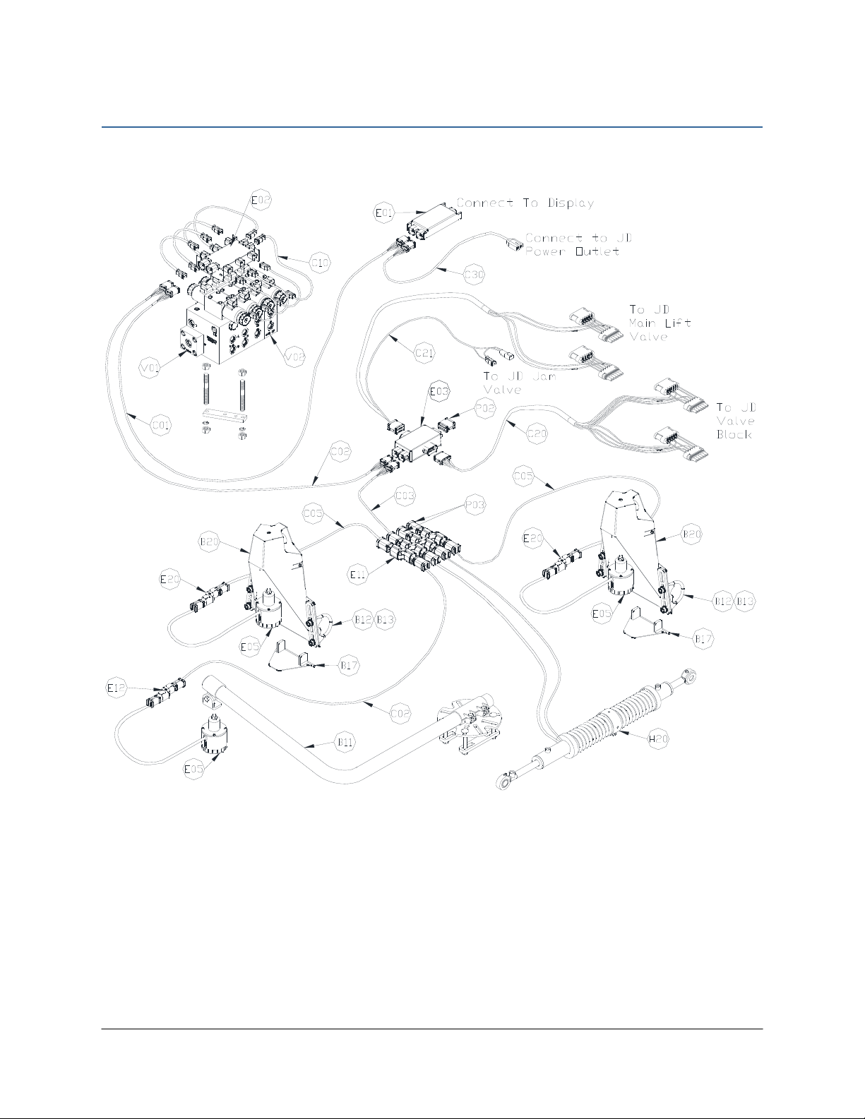
3General UC5 System Layout
Figure 1 illustrates the general layout of the UC5 system components:
Figure 1: General UC5 System Layout
4
4Kit Parts
4.1 Kit Overview
Figure 2: JD10A System Parts
5
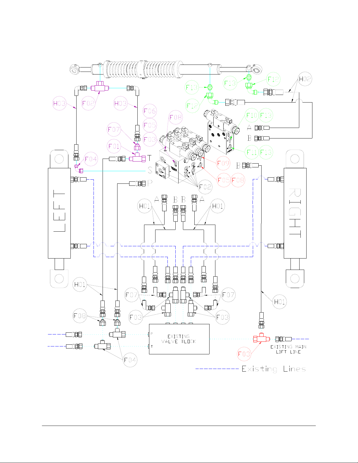
4.2 Hydraulic Plumbing
Figure 3: JD10A Hydraulic Plumbing
Note: Part numbers shown in RED are from fittings kit H11 (44865-37).
Part numbers shown in GREEN are from fittings kit H12 (44865-66).
Part numbers shown in PURPLE are from fittings kit H13 (44865-76).

6
4.3 List of Parts
Item Part Number Name Quantity
B05 44706-01 KIT CABLE TIE BLACK 10 PCS 21 IN 150 PCS 7.5 IN 1
B11 44743 MOUNTING BRACKET MAIN LIFT SENSOR UC4 PLUS 1
B12 105415 CLAMP ROUND 2IN PLATED 4
B13 105416 CLAMP ROUND 1-1/4 IN PLATED 4
B17 44972 SENSOR MOUNTING BRACKET LOW PROFILE RAINFLAP 16GA 2
B20 44971 SENSOR MOUNTING BRACKET LOW PROFILE 16GA 2
B25 44760 BRACKET MOUNTING LINEA ROLL JD 4920 1
C01 43220-10 CABLE UC5 NETWORK 14 AWG 10M 1
C02 43220-01 CABLE UC5 NETWORK 14 AWG 1M 2
C03 43220-03 CABLE UC5 NETWORK 14 AWG 3M 1
C05 43210-20 CABLE UC5 NETWORK 18 AWG 20M 2
C10 43230-04 CABLE UC5 VALVE 2PIN DT TO 2PIN DT 8
C20 43240-19 CABLE UC5 INTERFACE TILT JD (4920, 4930) 1
C21 43240-20 CABLE UC5 INTERFACE MAIN JD (4920, 4930) 1
C30 43250-07 CABLE UC5 BATTERY JD FUSED 1
E01 43710 UC5 CONTROLLER MODULE 1
E02 43720 UC5 VALVE MODULE 1
E03 43732 UC5 INPUT MODULE PASS THRU 1
E05 43750 UC5 ULTRASONIC SENSOR 3
E11 43765 UC5 NETWORK COUPLER 8-WAY 1
E12 43764 UC5 NETWORK COUPLER 2-WAY 1
E20 43764T UC5 NETWORK COUPLER 2-WAY WITH TERMINATOR 2
H01 44863-48 HOSE ASSEMBLY 122R2-06 40IN L 6FORX90 6FORX 7
H02 44863-31 HOSE ASSEMBLY 122R2-06 106 IN L 6FORX 6FORX 2
H10 44865-51 HYDRAULICS FITTING KIT - JD10 1
H11 44865-37 HYDRAULICS FITTING KIT - JD9 1
H12 44865-66 HYDRAULICS FITTING KIT - JD10A 1
H20 44795-202 ROLL POSITION CYLINDER 40.86IN 2PS AC JD 1
M02 UC5-BC-JD10A-INST
MANUAL INSTALLATION UC5 JOHN DEERE 4930, 4940 ACTIVE ROLL WITH PROP ML
1
P02 106602 UC5 NETWORK 12 PIN PLUG (A-KEY) 1
P03 105882 UC5 NETWORK 6 PIN PLUG 3
V01 44960D VALVE BLOCK ASSEM 3 STATION CC/LS PROP DT 4 1
V02 44962D VALVE ASSEMBLY EXPANSION DPOC PROP DT 4 BOLT 1

7
4.4 Hydraulic Parts Included with 44795-202
Item Part Number Name Quantity
H03 44862-21 HOSE ASSEMBLY 100R17(109)-04 106 IN L 4FORX 4FORX90 2
H13 44865-76 HYDRAULICS FITTING KIT - RPC 201/202 1
Do not use high speed power tools/drills when installing hardware.
The use of dielectric grease is not recommended on any NORAC electrical
connections.
To ensure all stainless steel hardware does not gall or seize apply a light coating of
the supplied Permatex Anti-seize grease to all threaded parts upon installation.
Permatex Anti-seize lubricant is preferred, but other similar anti-seize products
may be used.
8
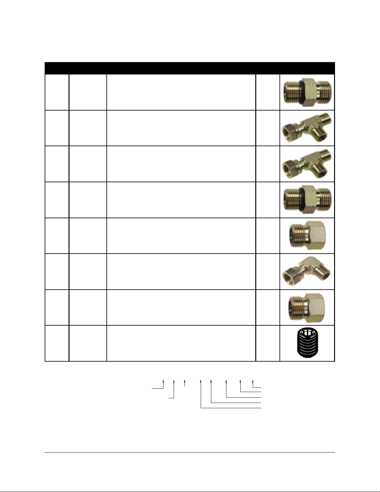
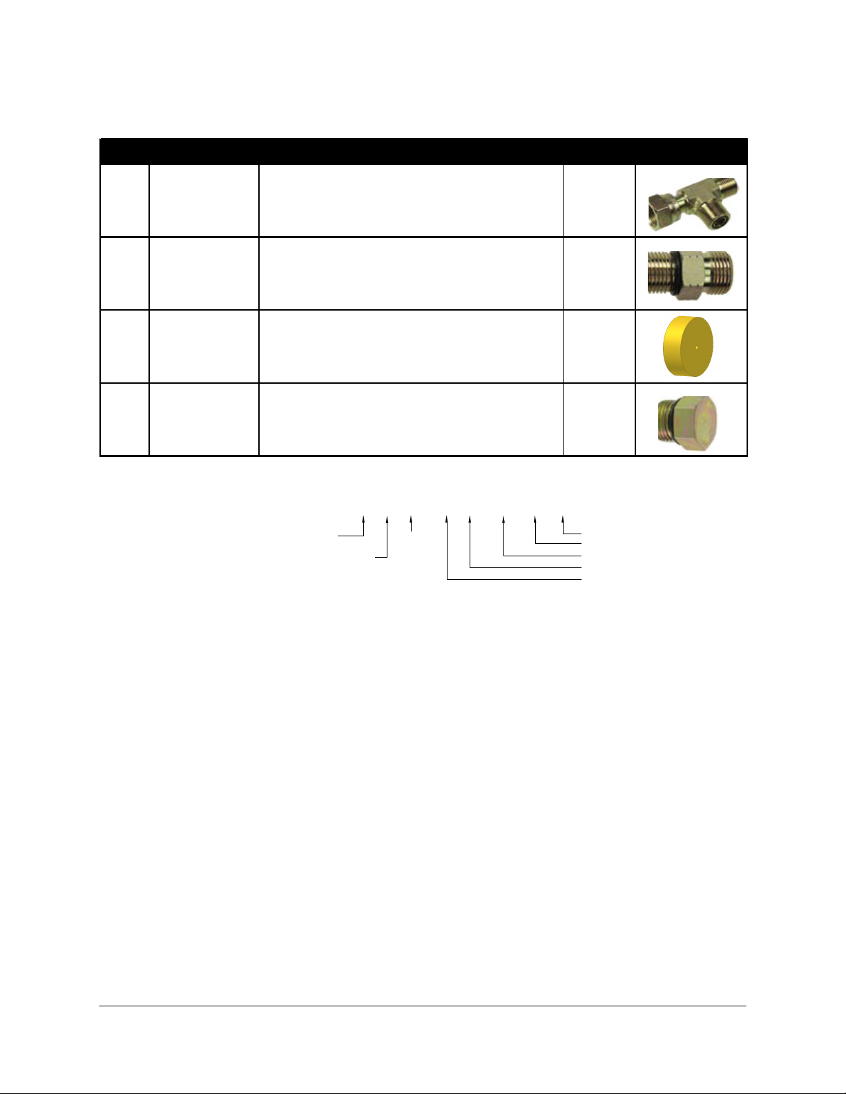
4.5 Hydraulic Fitting Kit Details (P/N: 44865-51)
Item Part Number Name Quantity Picture
F02 44917 MALE ADAPTER - 6MB-6MOR 6
F03 104586 TEE ADAPTER - 6FORXR 6MORT 5
F04 104885 TEE ADAPTER - 8FORXR 8MORT 2
F05 104693 COUPLING HYD 4MOR 4MB 1
F06 105226 MALE TO FEMALE ADATPER - 4MOR 6FORX 1
F07 104590 90 DEG ADAPTER - 6MOR 6FORX90 4
F08 104884 MALE TO FEMALE ADAPTER - 6MOR 8FORX 2
F10 105500 SETSCREW 1/4X3/8 1
6 M B - 6 M OR X 90
SIZE IN
1/16TH'S
GENDER: MALE
OR FEMALE
90° ANGLE
SWIVEL
TYPE
GENDER
SIZE
TYPE:
B - ORB
J - JIC
OR - FLAT
FACE
P - PIPE
Fitting Name
Example:
* Not all fittings are used in this installation.
9
4.6 Hydraulic Fitting Kit Details (P/N: 44865-37)
Item Part Number Name Quantity Picture
F03 104586 TEE ADAPTER - 6FORXR 6MORT 1
F05 44917 MALE ADAPTER - 6MB 6MOR 1
F08 44926 ORIFICE INSERT 3/64" 1
F09 104369 PLUG - 6MBP 1
6 M B - 6 M OR X 90
SIZE IN
1/16TH'S
GENDER: MALE
OR FEMALE
90° ANGLE
SWIVEL
TYPE
GENDER
SIZE
TYPE:
B - ORB
J - JIC
OR - FLAT
FACE
P - PIPE
Fitting Name
Example:
10
4.7 Hydraulic Fitting Kit Details (P/N: 44865-66)
Item Part Number Name Quantity
Picture
F10 44927 ORIFICE INSERT .031 IN ONE WAY 1
F11 44975 ORIFICE INSERT .036 IN ONE WAY 1
F12 104590 90 DEGREE ADAPTER - 6MOR 6FORX90 2
F13 44917 MALE TO MALE ADAPTER - 6MB 6MOR 4
6 M B - 6 M OR X 90
SIZE IN
1/16TH'S
GENDER: MALE
OR FEMALE
90° ANGLE
SWIVEL
TYPE
GENDER
SIZE
TYPE:
B - ORB
J - JIC
OR - FLAT
FACE
P - PIPE
Fitting Name
Example:

11
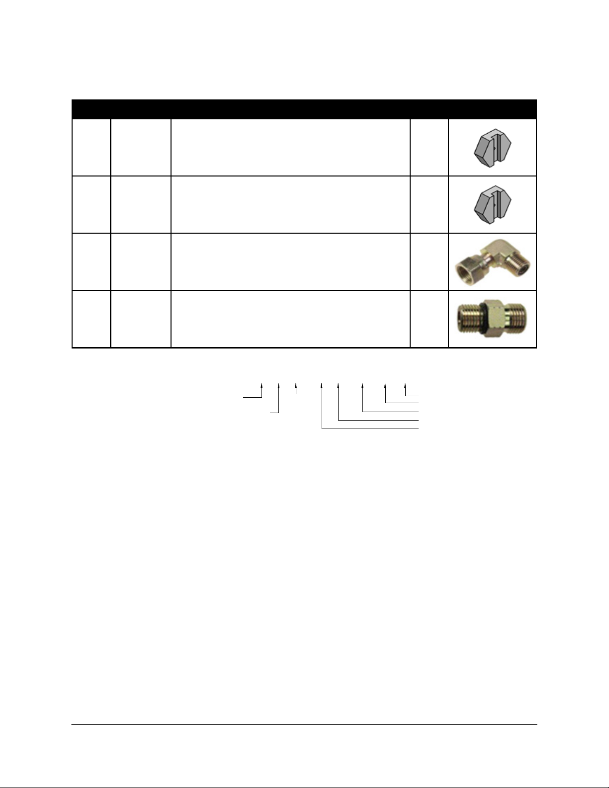
4.8 Hydraulic Fitting Kit Details (P/N: 44865-76)
Item Part Number Name Quantity
Picture
F01 104586 COUPLING HYD 6FORXR 6MORT 1
F02 104692 COUPLING HYD 4MORR 4FORXT 1
F03 104693 COUPLING HYD 4MOR 4MB 1
F04 104694 COUPLING HYD 4MOR 4FORX90 1
F05 104695 O-RING HYD 1/4IN FLAT FACE 1
F06 106651 ORIFICE INSERT INLINE 4 FLAT FACE O-RING FITTING -
.018" ORIFICE 1
F07 105226 COUPLING HYD 4MOR 6FORX 1
F08 105500 SETSCREW NC SKT 1/4X3/8 STAINLESS 1
6 M B - 6 M OR X 90
SIZE IN
1/16TH'S
GENDER: MALE
OR FEMALE
90° ANGLE
SWIVEL
TYPE
GENDER
SIZE
TYPE:
B - ORB
J - JIC
OR - FLAT
FACE
P - PIPE
Fitting Name
Example:
12
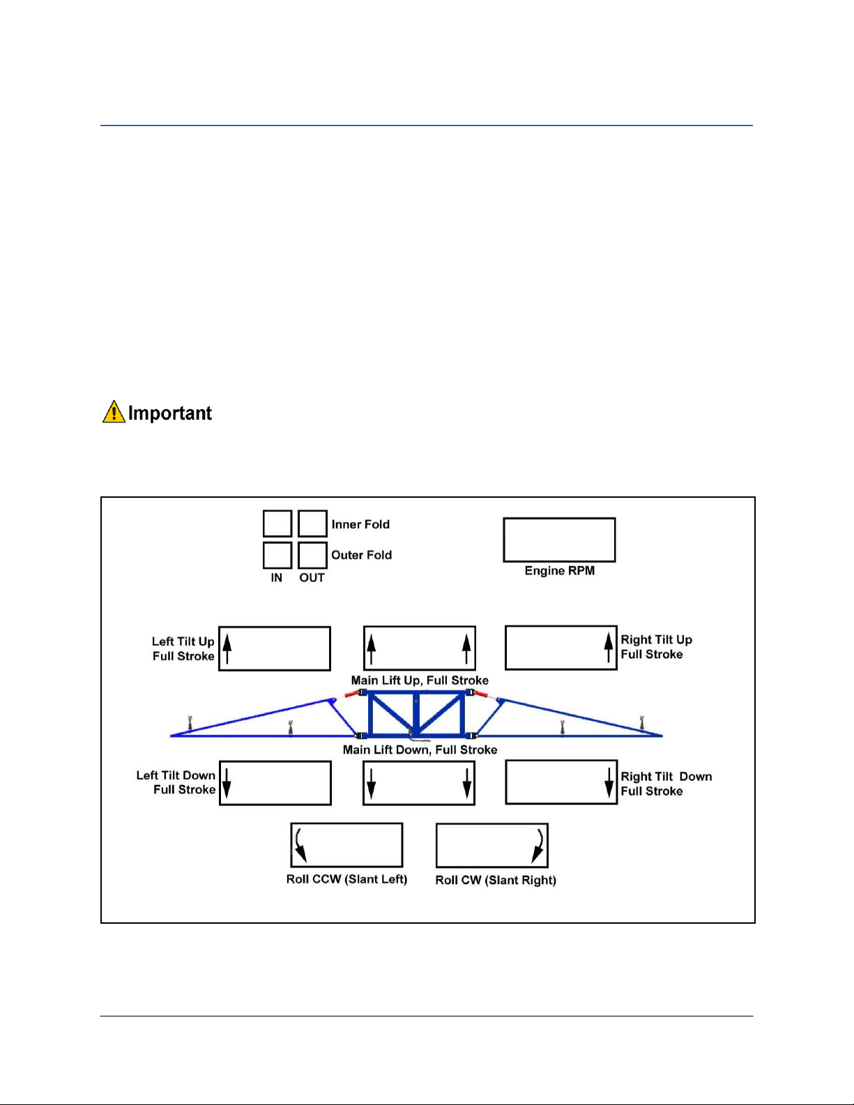
5Pre-Install Checklist
The pre-install checklist is necessary to check the existing sprayer functionality before the
installation.
1. Unfold the sprayer over a flat, unobstructed area (i.e. no power lines…etc.).
2. Ensure all boom-fold operations are functional (place a check mark in boxes below).
3. Bring engine to field-operational RPM and record below.
4. Record the time (seconds) it takes for a full stroke for all boom functions. To ensure
repeatable measurements, take the average of 3 trials.
5. Not all sprayers will have the functions listed below in Figure 4.
Ensure the boom has sufficient travel so it does not contact the ground during
these tests.
Figure 4: Pre-Install Boom Speeds

13
6Ultrasonic Sensor Installation
6.1 Ultrasonic Sensor Serial Number Arrangement
When installing the UC5 sensors, start with the smallest serial number on the left-hand side,
and proceed to the largest serial number on the right hand side. Each UC5 sensor has a serial
number stamped on the sensor housing.
Apply a light coating of the supplied Permatex Anti-seize grease to all threaded
parts upon installation.
Figure 5: Sensor Serial Number Arrangement
14
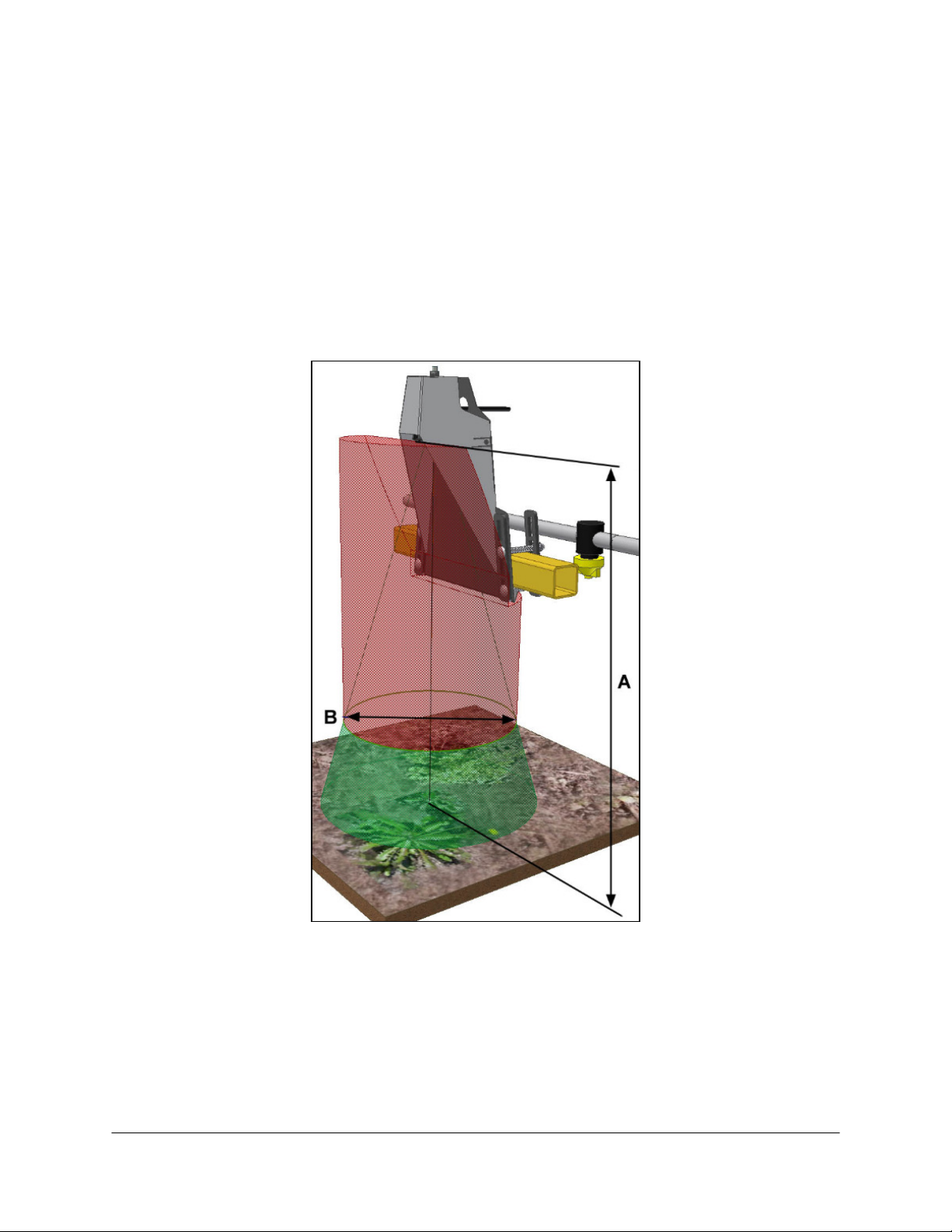
6.2 Ultrasonic Wing Sensor Mounting Guidelines
The following guidelines will ensure optimal sensor performance and prevent sensor
measurement error.
1. In its lowest position, the sensor must be 9 inches (23 cm) or more from the ground.
2. Ensure that there are no obstructions within a 12-inch diameter circle projected directly
below the center of the sensor.
3. The sensor should be approximately vertical at normal operating heights.
Figure 6: Sensor Mounting Guidelines

15
6.3 Low Profile Bracket Mounting Guidelines
1. Minimize the distance between the bolts to prevent bending the bracket and prevent the
bracket from loosening over time.
2. Ensure the bracket is mounted tight against the bottom of the boom, minimizing the
distance between the boom structure and the angled flange.
Figure 7: Bracket Mounting Guidelines
A problem can arise if a sensor is not mounted correctly. It is possible for the
sensor to read off of the boom instead of the ground. This may only become
apparent once the control system is switched from soil to crop mode.
Also be careful that the sensor bracket does not collide with any other part of the
boom when the boom is folded to transport position. If possible, mount the sensor
brackets while the booms are folded to ensure they will not cause interference.

16
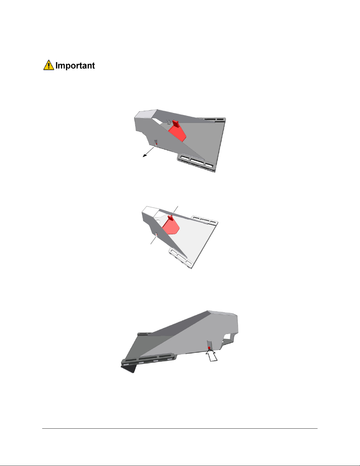
6.4 Wing Sensor Installation
1. The sensor bracket should be oriented forward (ahead of the boom).
2. Typically the best mounting location for the wing sensor brackets will be near the end of
the boom tips, approximately two feet (60cm) from the end.
3. Depending on the boom design, some breakaway sections will lift upwards as they break
back. If the sensor is mounted to this portion of the boom, the system will force the boom
downwards towards the ground as the boom folds backwards.
4. Mount the NORAC UC5 ultrasonic sensor into the sensor bracket and run the sensor
cable either through hole in the back or through the side cut-out and behind the bracket.
Ensure the cable is clear of moving parts and will not be damaged during folding.
Figure 8: Bracket Mounting Example
5. Exhaust clamps (B12 and B13) can be used if mounting the sensor brackets to a portion of
the boom with round tubing.
Figure 9: Bracket Mounted with Exhaust Clamps
Front
Front
17
6.5 Rainflap Installation
Rainflaps are only installed in the wing sensor brackets.
1. Insert one side of the rainflap rod into the pre-bent hinge tab on the sensor bracket.
(Figure 10)
Figure 10: Rainflap Rod in Pre-Bent Hinge Tab
2. Align the other side of the rainflap rod with the unbent hinge tab. (Figure 11)
Figure 11: Align Rainflap Rod
3. Bend the hinge tab inward over the rainflap rod until the hinge tab fits securely in the
detent groove on the backside of the sensor bracket. (Figure 12)
Figure 12: Bend Rainflap Hinge Tab
4. Ensure the rainflap actuates smoothly when the bracket is turned upside down and returns
to the open position when the sensor bracket is returned to its operating position (sensor
pointing downwards toward the ground).
Other manuals for UC5 Topcon X30
55
Table of contents
Other Norac Paint Sprayer manuals

Norac
Norac UC4.5 User manual

Norac
Norac UC4+ User manual

Norac
Norac UC4 Total Control User manual

Norac
Norac UC5 Topcon X30 User manual

Norac
Norac UC5 Topcon X30 User manual

Norac
Norac UC5 Topcon X30 User manual

Norac
Norac UC 4.5 Hagie STS10 User manual

Norac
Norac UC4.5 User manual

Norac
Norac UC5 Topcon X30 User manual

Norac
Norac UC4.5 User manual

Norac
Norac UC4+ User manual

Norac
Norac UC4.5 User manual

Norac
Norac UC4.5 User manual

Norac
Norac UC5 Topcon X30 User manual

Norac
Norac UC5 Topcon X30 User manual

Norac
Norac UC4.5 User manual

Norac
Norac UC4.5 User manual

Norac
Norac UC5 Topcon X30 User manual

Norac
Norac UC4.5 User manual

Norac
Norac UC5 Topcon X30 User manual


