Norac UC4.5 User manual

b
AGRIFAC
Installation Manual
AG1

Printed in Canada
Copyright 2014 by NORAC Systems International Inc.
Reorder P/N: UC4.5-BC-AG1-INST Rev C (AGRIFAC)
NOTICE: NORAC Systems International Inc. reserves the right to improve products and their specifications without notice and
without the requirement to update products sold previously. Every effort has been made to ensure the accuracy of the information
contained in this manual. The technical information in this manual was reviewed at the time of approval for publication.

Contents
1Introduction................................................................................................................ 1
2General UC4.5 System Layout................................................................................. 2
3Kit Parts ...................................................................................................................... 3
4Ultrasonic Sensor Installation .................................................................................. 5
5Roll Sensor Installation............................................................................................ 10
6Electrical Installation ............................................................................................... 12
7Hydraulic Installation .............................................................................................. 15
8Software Setup......................................................................................................... 17
9Cable Drawings ........................................................................................................ 18
1
1Introduction
Congratulations on your purchase of the NORAC UC4.5 Spray Height Control System. This
system is manufactured with top quality components and is engineered using the latest
technology to provide operating reliability unmatched for years to come.
When properly used the system can provide protection from sprayer boom damage, improve
sprayer efficiency, and ensure chemicals are applied correctly.
Please take the time to read this manual completely before attempting to install the system. A
thorough understanding of this manual will ensure that you receive the maximum benefit from
the system.
Your input can help make us better! If you find issues or have suggestions regarding the parts
list or the installation procedure, please don’t hesitate to contact us.
NORAC does not operate the angle corrector on AGRIFAC sprayers. It is
recommended that this feature be disabled to avoid interference with the UC4.5
Spray Height Control system operation.
Every effort has been made to ensure the accuracy of the information contained in
this manual. All parts supplied are selected to specially fit the sprayer to facilitate
a complete installation. However, NORAC cannot guarantee all parts fit as
intended due to the variations of the sprayer by the manufacturer.
Please read this manual in its entirety before attempting installation.

2
2General UC4.5 System Layout
Figure 1 illustrates the general layout of the UC4.5 system components:
Figure 1: General UC4.5 System Layout
3
3Kit Parts
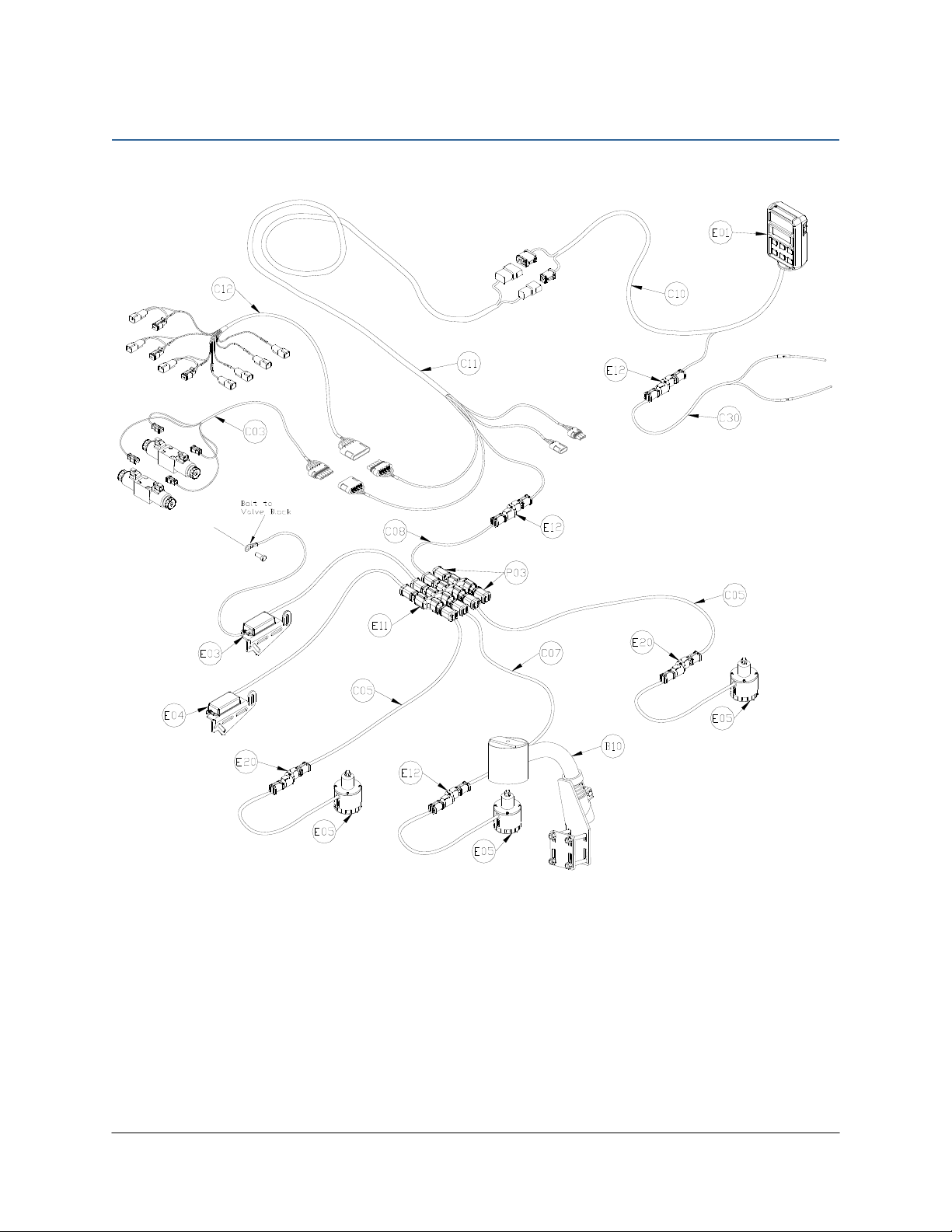
3.1 Kit Overview
Figure 2: AG1 System Parts

4
3.2 List of Parts
Item Part Number Name Quantity
B10 44728 MOUNTING BRACKET COMPLETE UC4 BREAKAWAY EXTENDED 1
C03 44656D CABLE VALVE VARIABLE RATE DT 1
C05 43210-20 CABLE UC5 NETWORK 18 AWG 20M 2
C07 43220-03 CABLE UC5 NETWORK 14 AWG 3M 1
C08 43220-05 CABLE UC5 NETWORK 14 AWG 5M 1
C10 44650-51 CABLE UC4.5 POWER GENERIC PULL-TYPE 1
C11 44651-50 CABLE UC4.5 EXTENSION VALVE GENERIC 1
C12 44658-97 CABLE UC4 INTERFACE DT06-2X GND2 - DIODE 1
C30 43250-12 CABLE UC5 BATTERY PIGTAIL FUSED (ECU & SIG) 1
E01 45100 UC4.5 BOOM CONTROL PANEL 1
E03 43742 UC5 ROLL SENSOR W TEMPERATURE PROBE 1
E04 43741 UC5 ROLL SENSOR VER. 2 1
E05 43750 UC5 ULTRASONIC SENSOR 3
E11 43765 UC5 NETWORK COUPLER 8-WAY 1
E12 43764 UC5 NETWORK COUPLER 2-WAY 3
E20 43764T UC5 NETWORK COUPLER 2-WAY WITH TERMINATOR 2
M01
UC4.5-BC-MANUAL-
OPERATOR
OPERATOR MANUAL UC4.5 SPRAY HEIGHT CONTROL 1
M02 UC4.5-BC-AG1-INST MANUAL INSTALLATION UC4.5 AGRIFAC 1
P03 105882 UC5 NETWORK 6 PIN PLUG 2
V01 106063 VALVE HYD SOL CC PROPORTIONAL 12V DEUTSCH CONNECTORS 2
Do not use high speed power tools/drills when installing hardware.
The use of dielectric grease is not recommended on any NORAC electrical
connections.
To ensure all stainless steel hardware does not gall or seize apply a light coating of
the supplied Permatex Anti-seize grease to all threaded parts upon installation.
Permatex Anti-seize lubricant is preferred, but other similar anti-seize products
may be used.

5
4Ultrasonic Sensor Installation
4.1 Bracket Assembly
1. Assemble the breakaway sensor bracket as illustrated in Figure 3, following the instructions
below.
Figure 3: Breakaway Bracket Assembly
2. Compress the spring and insert it together with the collar into the base.
3. Slide the tube through the assembled part.
4. Using the bolt and nut, tighten the collar to the tube with the sensor tube centered.
5. Apply a small amount of grease to the rotating surfaces of the bracket.

6
4.2 Ultrasonic Sensor Serial Number Arrangement
When installing the UC5 sensors, start with the smallest serial number on the left-hand side,
and proceed to the largest serial number on the right hand side. Each UC5 sensor has a serial
number stamped on the sensor housing.
Apply a light coating of the supplied Permatex Anti-seize grease to all threaded
parts upon installation.
Figure 4: Sensor Serial Number Arrangement
7
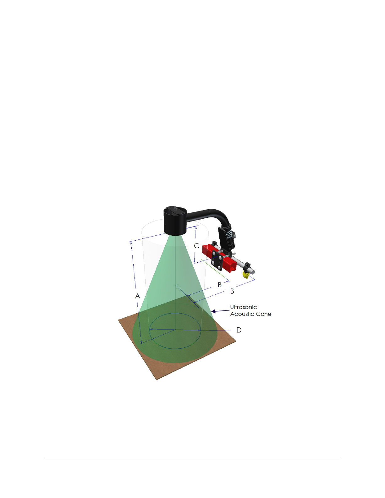
4.3 Ultrasonic Sensor Mounting Guidelines
The following guidelines will ensure optimal sensor performance and prevent sensor
measurement error. These rules should be followed for both the wing sensors and the main
lift (middle) sensor.
1. In its lowest position, the sensor must be 9 inches (23 cm) or more from the ground (A).
2. The centerline of the acoustic cone should be approximately vertical at normal operating
heights (A).
3. The bottom of the sensor must be at least 9 inches in front of the spray nozzles and boom
structure (B). (This does not apply for the main lift sensor)
4. The bottom of the sensor must be at least 9 inches above the spray nozzles (C).
5. Ensure there are no other obstructions with a 12 inch (23 cm) diameter circle projected
directly below the sensor (D).
Figure 5: Sensor Mounting Guidelines

8
4.4 Wing Sensor Installation
1. The sensor bracket should be oriented forward (ahead of the boom).
2. Typically the best mounting location for the wing sensor brackets will be near the end of
the boom tips, approximately two feet (60cm) from the end.
3. Depending on the boom design, some breakaway sections will lift upwards as they break
back. If the sensor is mounted to this portion of the boom, the system will force the boom
downwards towards the ground as the boom folds backwards.
4. Mount the NORAC ultrasonic sensor into the sensor bracket and run the sensor cable
through the sensor tube.
A problem can arise if a sensor is not mounted correctly. It is possible for the
sensor to read off of the boom instead of the ground. This may only become
apparent once the controller is switched from soil to crop mode.
Also be careful that the sensor bracket does not collide with any other part of the
boom when the boom is folded to transport position. If possible, mount the sensor
brackets while the booms are folded to ensure they will not cause interference.
Figure 6: Sensor Reading Off Boom

9
4.5 Main Lift Sensor Installation
1. There are a variety of ways to mount the main lift bracket on most sprayers. The bracket
should position the sensor approximately in the center of the sprayer, forward of the
boom.
2. Mount the ultrasonic sensor to the main lift bracket. Run the sensor cable down the center
of the main lift bracket tube.
Figure 7: Example Mounting of the Main Lift Bracket
Avoid mounting the main lift sensor over or near a wheel-track. Measurements
from the wheel-track do not provide an accurate crop height and will cause
measurement and control error.
Ensure the bracket does not collide with any other part of the sprayer throughout
the full range of main lift motion.

10
5Roll Sensor Installation
5.1 Bracket Assembly
1. Securely mount the roll sensors to the included roll sensor brackets using the #6 machine
screws. Tighten screws to 10 in-lbs (1.1 Nm).
2. The orientation of the mounted roll sensor to the roll sensor bracket will depend on the
bracket mounting. The roll sensor CANbus connector must be pointing towards the right
side of the sprayer (when looking from the rear of the sprayer).
Figure 8: Mounting Roll Sensor to Bracket
Figure 9: Roll Sensor Orientation - Connector Facing Right Wing

11
5.2 Roll Sensor Mounting Guidelines: Center Pivot Booms
1. When mounting the roll sensors, mount the roll sensor without the temperature probe on
the boom frame and the roll sensor with the temperature probe on the chassis (non-
pivoting portion of the sprayer). For optimal performance, minimize the distance between
the roll sensors (A) and minimize the height from each roll sensor to the pivot point (B).
Figure 10: Roll Sensor Mounting on a Center Pivot Suspended Boom
2. Ensure the roll sensors are relatively level when the sprayer boom and chassis are level.
3. Both roll sensor cables should be pointing towards the right hand wing of the sprayer.
4. Ensure both roll sensors are mounted adequately and that the cables provide enough slack
to allow sufficient boom roll.
Figure 11: Example Roll Sensor Mounting
5.3 Temperature Probe
Fasten the temperature probe from E03 to the valve block using the included 3/8x1/2” bolt.
Boom Frame
Chassis

12
6Electrical Installation
1. Install the UC4.5 Control Panel (E01) in the cab of the sprayer. Mount the panel where it
will be clearly visible and within easy reach of the operator.
A good spot to mount the UC4.5 control panel is on the right hand side of the cab to the
Roll Over Protection Bar (ROP). Four pilot holes for the screws provided need to be
drilled to facilitate the control panel mounting.
Another option is to purchase an adapter for the flexible panel mount that has a 3/8" NC
threaded stud on the end to bolt through an existing mount. These can be found at your
local outdoor store as a RAM mount part number RAM-B-236. (See http://www.ram-
mount.com/)
Figure 12: Cable Configurations: C10, C11 and C30
2. Connect the UC4.5 power cable (C10) to the UC4.5 control panel in the sprayer cab.
Ensure both plugs (P16 and P4) are connected to the panel. Cable tie C10 to the RAM
mount to help provide strain relief.
Ensure the UC4.5 control panel’s power is OFF for the remaining installation
(Bottom of switch pressed IN).
3. Connect the power cable connector (P6A) to C30 using a 2-way coupler (E12). Connect
C30 to an appropriate power supply.
4. Route the P12 and P6B of C10 out of the cab.
5. Connect the P12/P6B from C10 to R12/R6 of C11 at the hitch. This connection is the hitch
disconnect.
6. Route C11 to the vicinity of the sprayer valve block.
13
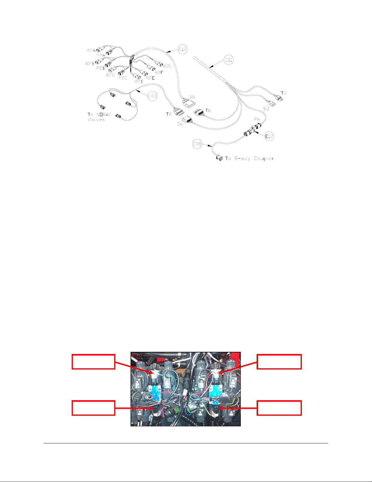
Figure 13: Cable Configurations: C03, C08, C11 and C12
7. Connect the 6-pin shroud (S6) on C12 to the 6-pin tower (T6) on C11. Route the free end
of C12 to the existing valve block.
8. Insert the connector tees (R2A-P2A and R2C-P2C) on C12 between the matching
connections on the existing sprayer valve harness: MAIN UP and MAIN DOWN. The
function is labeled on the branch wire for each tee. An AGRIFAC supplied extension cable
may be required to reach the main lift connections. The second main up tee (R2B-P2B is
not used for this installation.
9. Unplug the existing connectors on the sprayer left and right boom control valve
connections. There are four connectors to unplug: Left Up, Left Down, Right Up and Right
Down.
10. Connect the four connectors of C12 (R2D, R2E, R2F and R2G) to the matching connectors
of sprayer cable(s). The function (e.g. “LEFT UP”) is labeled on the branch wire of C12 for
each connector.
11. Connect the 6-pin tower on C03 to the 6-pin shroud on C11. The connectors on the valve
cable (C03) are marked RIGHT UP, LEFT UP, RIGHT DOWN and LEFT DOWN.
Connect as shown in Figure 14.
Figure 14: Valve Cable Connections
Left Up
Left Down
Right Up
Right Down

14
12. Fasten the 8-way coupler (E11) to the boom with cable ties.
13. Connect P6 on C11 to a 2-way coupler (E12). Connect cable C08 between the 2-way
coupler and the 8-way coupler.
14. Connect both roll sensors to the 8-way coupler.
15. Connect the main lift sensor to the 8-way coupler using cable C07 and a 2-way coupler
(E12). Cable C07 and item E12 may not be needed if the 8-way coupler is mounted close
enough to the main lift sensor.
16. Connect two cables (C05) to the 8-way coupler and route along the booms to the wing
sensors. Follow existing cables and hoses to be sure the cable will not be pinched or
stretched.
17. At the sensor brackets, attach a 2-way coupler with terminator (E20) to the sprayer boom.
The 2-way coupler with terminator is the white two way coupler. Plug the sensor and the
CANbus cable into the 2-way coupler.
IMPORTANT:
Provide enough slack in all cables to account for the movement of the main
section, parallel lift, and FOLDING boom movement.

15
7Hydraulic Installation
Ensure all pressure has been bled from the system before disconnecting any lines
or fittings. Hydraulic pressure will exist on the wing tilt circuits unless the wings
are being supported by other means. The hydraulic installation may be performed
with the wings in transport position, resting on the ground or with the tilt cylinders
fully extended.
Component failure due to oil contamination is not covered under the NORAC
UC4.5 system warranty. It is recommended that a qualified technician perform the
hydraulic installation.
7.1 Valve Installation
1. Install the valves onto the sprayer valve block as shown in Figure 15.
Figure 15: NORAC Valves Installed on Sprayer Valve Block
NORAC recommends the addition of an extra in-line filter to ensure proper
oil filtration to the proportional valves.
NORAC recommends installing one-way restrictors on the down direction of
the wing cylinders to control the down speed when wings are manually
operated.
Ensure that all other restrictors are removed from the wing cylinders.
16
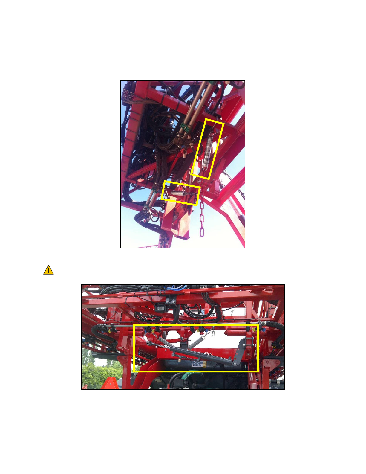
7.2 Spring Installation
1. Install two (2) springs (not included in kit) to put tension on the center section of the
boom. The springs should have a 4-5cm diameter with a wire diameter of 3-4mm.
Figure 16: Springs Installed
NORAC also recommends installing a damper cylinder.
Figure 17: Damper Cylinder Installed

17
8Software Setup
1. Start up the sprayer and test the sprayer’s functionality. The control panel does not need
to be powered on for the original boom function switches to operate. Unfold the booms
and raise/lower each boom and the main section.
Confirm that the cabling and hoses are agreeable to the entire range of motion.
2. If any functions do not work, review the hydraulic and electrical portions of this manual to
check for proper installation.
3. Turn on the power for the UC4.5 Control Panel using the switch on the side of its chassis.
4. Begin the AUTOMATIC SYSTEM SETUP procedure as described in the UC4.5 Spray
Height Control Operator’s Manual (M01).
Other manuals for UC4.5
31
Table of contents
Other Norac Paint Sprayer manuals

Norac
Norac UC5 Topcon X30 User manual

Norac
Norac UC5 Topcon X30 User manual

Norac
Norac UC5 Topcon X30 User manual

Norac
Norac UC5 Topcon X30 User manual

Norac
Norac UC4+ User manual

Norac
Norac UC5 Topcon X30 User manual

Norac
Norac UC4+ User manual

Norac
Norac UC4+ User manual

Norac
Norac UC 4.5 Hagie STS10 User manual

Norac
Norac UC4.5 User manual

Norac
Norac UC4.5 User manual

Norac
Norac UC4.5 User manual

Norac
Norac UC5 Topcon X30 User manual

Norac
Norac UC4.5 User manual

Norac
Norac UC4.5 User manual

Norac
Norac UC4.5 User manual

Norac
Norac UC4 Total Control User manual

Norac
Norac UC5 Topcon X30 User manual

Norac
Norac UC4.5 User manual

Norac
Norac UC4.5 User manual


