T4W PIK XRP User manual

OPERATION MANUAL
PIKqXRP

2
Parts list ........................................................................................3
Cause ...........................................................................................4
Repair ...........................................................................................4
Trouble .......................................................................................... 4
Technical Data:..............................................................................5
Safety............................................................................................ 5
Instructions for use........................................................................6
Method of Application Material ......................................................7
Connection schema. .....................................................................7
Cleaning a gun ..............................................................................7

3
1 Air Cap Set 13 Air Valve Shaft
2 Fluide Nozzle 14 Air Valve Gasket
3 Distribute Seat 15 Spring
4 Gun Body 16 Screw
5 Fluid Inlet For 600c.c 17 Fan Control Assembly
5A Fluid Inlet For 400c.c 18 Control Knob
6 Needle Packing 19 Screw
7 Spring 20 Air Inlet
8 Needle Packing Seat 21 Air Control Set
9 Fluid Needle seat 22 Pin
10 Fluid Needle Spring 23 Hollow Pin
11 Control Knob Set 24 E-Stopper
12 Air Valve Seat 25 Trigger
11
10
9
8
7
6
5
4
A
A
A
A
1
2
3
24
23
22
21
20
19
12
13
14
15 16
5A
25
18
17
Parts list

4
Please read the operating instructions carefully before using the device, and
keep them in a safe place.
Cause
• Foreign substances between uid nozzle and uid needle prevent sealing.
• Self tensioning needle sealing damaged or lost.
• Horn air holes or air circuit clogged.
• Dirt on uid needle tip or air outlet.
• Too little material in cup, uid nozzle not tight, needle
sealing damaged, nozzle set dirty or damaged.
• Atomization air ows through the paint channel to the cup.
The paint nozzle is not tigh enough. Air nozzle is not completely screwed,
the air net clogged and the seat is defective or nozzle insert is damaged.
Repair
• Clean uid needle and uid nozzle in thinner or use new uid nozzle.
• Replace needle sealing.
• Soak in thinner, after wards clean with nozzle-cleaning needle.
• Turn air nozzle by 180 degrees. If defective pattern
remains, clean paint outlet in air nozzle.
• Rell material, tighten parts, if necessary clean or replace.
• Tighten parts accordingly, clean or replace.
Trouble
• Gun leaks from uid nozzle.
• Paint emerges from uid needle-needle sealing.
• Spray pattern in sickle shape.
• Drop-like or oval shaped pattern.
• Paint spray utters.
• Material hubbies or “boils” in paint cup.

5
Technical Data:
Available nozzle ________________________________________________1.3mm: No.59474
________________________________________________________________1.4mm: No.59528
________________________________________________________________1.5mm: No.59529
________________________________________________________________1.7mm: No.59530
________________________________________________________________2.1mm: No.59531
________________________________________________________________2.5mm: No.59532
Pressure required _____________________________________________ 1-2 bar (10-28 psi)
Air Consumption___________________________________________________150~280 l/min
Air connection________________________________________________________ 1/4” PS(M)
Net weight ________________________________________________________________ 450g
Safety
Never point the tool against people and animals - coating
materials or compressed air may be the cause of injuries. It is
forbidden to use any other gas instead of compressed air.
• The use of other gases can lead to serious injury, or threaten to cause a re hazard.
• When connecting the tool to the compressed air system should take into account
the space needed for the hose to prevent damage to the hose or ttings.
• At work should be ensured adequate ventilation. Lack of ventilation
can cause damage to health, or threaten to cause a re hazard.
• The tool should be used away from sources of heat and re, as
this could cause damage to or deterioration of functioning.
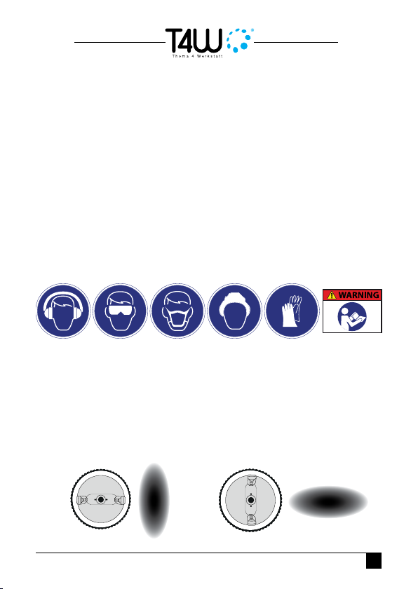
• Observe general safety rules when performing work of coating
materials and used appropriately selected personal protective
equipment such as goggles, masks, gloves and overalls.
• Never leave the assembled air system without the supervision of the person
entitled to maintenance. Do not allow children near the assembled air system.
• Supply compressed air under high pressure, can cause kickback
tool in a direction opposite to the direction of ejection of the coating
material. It should be especially careful, because the recoil forces
may, in certain circumstances, result in multiple injuries.
• It is recommended to try the tool before you start. It is recommended that
utility workers are properly trained. This will improve safety signicantly.
• Follow manufacturer of coating materials and use them in

6
accordance with the stated principles of personal protective
equipment, re and environmental protection. Failure to follow
manufacturer’s coating materials, can lead to serious injury.
• To determine compatibility with the applicable coating materials, a list of
materials used in the construction of the tool will be available on request.
• When working with compressed air throughout the system collects
energy. Use caution when working and rest periods to avoid the danger
that may result from the stored energy of compressed air.
• Always use an electrostatic discharge hoses.
• Never block the outlet nozzle holes with your ngers.
• Do not modify the equipment on their own. Find out whether all the parts
are in working order, and replace if worn only new and original.
• In the event of an accident disconnect the unit from the power source.
Follow the general principles of health and safety in the workplace.
Never direct the coating material to a heat source or re, it could cause
a re.
Instructions for use
Flow control.
The stream can also be adjusted using the air cap die.
A) You gain by turning the air cap so
that the ends are on the sides of the
gun.
B) You gain by turning the air cap
so that the ends are aligned with the
trigger.

7
* Check the documentation that provides the producer jets to impose gun.
Method of Application Material
Connection schema.
Cleaning a gun
Never use a metal brush for cleaning gun. Never clean the whole
gun dipping in a solvent.
• Remove the gun from the power supply.
• Empty the paint and remove it.
• Manually remove the air cap.
• Manually remove the paint adjustment (5)
• Remove the spring (13)

8
• Pull the trigger
• Hand gently pull the needle (16)
• The key attached to the gun unscrew the nozzle (2)
• Put the nozzle needle and air cap to the solvent (2,16,1)
• Use the included brush, wash them gently.
• Use a brush to clean the inside of the solvent gun
• Use the cloth with clean solvent tank and gun body.
• Assemble everything back


Thoma
Tel./Fax: +48 95 741 11 62
info@t4w.eu • www.t4w.eu
This manual suits for next models
6
Table of contents
Other T4W Paint Sprayer manuals