norbar PRO-TEST 40 Service manual

PROFESSIONAL TORQUE TESTER
PRO-TEST 40, 400 & 1500ER
OPERATOR’S HANDBOOK (PART No 34237) Issue 4
(ENGLISH)
FOR USE WITH PRO-TEST’S FITTED WITH VERSION 37701.101 & 37701.102 SOFTWARE
MODEL NUMBERS COVERED BY THIS MANUAL
43180 PRO-TEST 40 TRANSDUCER
43181 PRO-TEST 400 TRANSDUCER
43189 PRO-TEST 1500ER TRANSDUCER
43184 PRO-TEST DISPLAY MODULE
NORBAR TORQUE TOOLS LTD, Beaumont Road, Banbury, Oxon, OX16 7XJ, UNITED KINGDOM
Tel : + 44 (0) 1295 270333, Fax : + 44 (0) 1295 753643

CONTENTS
PAGE
Introduction 1
Assembly Diagram 1
Operating Instructions 2
Set Up Menus and Options 4
RS-232-C Serial Data Output Interface 6
Print Inhibit Controller Option 7
Specifications 8
Trouble Shooting 10

PRO-TEST OPERATORS HANDBOOK PAGE 1 OF 10
ISSUE 4
AUGUST 1998
INTRODUCTION
The Professional Torque Tester (Pro-Test) has been designed as an accurate, cost effective
and easy to operate instrument for testing and calibrating all types of torque wrenches and torque
limiting screw drivers.
Pro-Test transducers are mounted in aluminium cast housings along with all the necessary
electronics to produce an output for the display module and RS-232-C interface. The housings can
be mounted for either horizontal, clockwise, or anti-clockwise torque testing.
The function of the front panel buttons is identified on the display to facilitate quick and easy
selection of the operating mode most suitable for the tool to be tested, i.e. track, peak memory with
manual reset, peak memory with auto reset, first peak memory with manual reset, or first peak
memory with auto reset. These buttons are also used to drive the Set-up Menus if changes to the
operational parameters of the Pro-Test are required. These include, language of operation,
measurement units to be enabled/disabled, RS-232-C communication parameters, auto reset hold
time, first peak memory sensitivity and modes of operation to be enabled/disabled. The Zero button is
only active in the track mode.
Pro-Test transducers are calibrated in the clockwise direction only as standard, the anti-
clockwise direction of operation will be inhibited unless the transducer has been additionally calibrated
in this direction. The direction of use is identified on the display and RS232C output
Optional extra’s include a Mounting Bracket, 1” sq x 36mm Hex Socket, Print Inhibit
Controller, Data Printer and 12 Volt DC power supply for use in vehicles.
ASSEMBLY DIAGRAM
43184
38793
62198 (OPTIONAL)
70
2 HOLES M10
38796
29179 3/4" TO 36mm SOCKET
29189 3/4" TO 22mm SOCKET
29134 1/2" TO 22mm SOCKET
29067 3/8" TO 10mm SOCKET
29190 1" TO 36mm SOCKET
2 HOLES ø10
25429
43180 PRO-TEST 40
43181 PRO-TEST 400
43182 PRO-TEST 1000
43183 PRO-TEST 1500
43180 PRO-TEST 40
43181 PRO-TEST 400
43189 PRO-TEST 1500ER

PRO-TEST OPERATORS HANDBOOK PAGE 2 OF 10
ISSUE 4
AUGUST 1998
OPERATING INSTRUCTIONS
1. Securely mount the Pro-Test transducer in the plane of operation required to a bench top,wall or
the additional mounting bracket (part number 62198) with the 2 fixing bolts supplied.
IMPORTANT !
The un-bolted end of the unit, must always be in contact with a supporting surface.
MOUNTING POSITION TO ENABLE CLOCKWISE TESTING.
(bolts to be hand tightened with allen key provided)
MOUNTING POSITION TO ENABLE ANTI-CLOCKWISE TESTING.
(bolts to be hand tightened with allen key provided)
MOUNTING POSITION TO ENABLE CLOCKWISE AND ANTI-CLOCKWISE TESTING
IMPORTANT !
Bolts must be torque tightened to 50 Nm, and replaced when removed.
2. Locate the 2 holes in the bottom of the Pro-Test Display Unit on to the bolt heads protruding from
the transducer housing. Fit connecting lead between Display Unit and Transducer.
Vertical
Testing
(bench mounted)
Vertical
Testing
(wall mounted)
Vertical
Testing
(bench mounted)
Vertical
Testing
(wall mounted)
Horizontal
Testing
(bench mounted)
Vertical
Testing
(wall mounted)

PRO-TEST OPERATORS HANDBOOK PAGE 3 OF 10
ISSUE 4
AUGUST 1998
3. Plug Power Supply into back of transducer housing then plug mains lead into Power Supply.
If a mains plug is not fitted, wire as follows :
BROWN-LIVE BLUE-NEUTRAL GREEN / YELLOW-EARTH
WARNING! It is important that live, neutral and earth are all connected
between the Pro-Test and mains power supply. If no earth is available (2 wire
mains power supply) it is recommended that a separate earth is connected
between the transducer housing (the bottom right hand fixing screw in the
corner of the back panel is ideal) and a suitable earth.
4. If power supply has an ON/OFF fitted, switch to ‘ON’.
5. Wait 2 seconds for initialisation and allow 5 minutes for the instrument to warm up and stabilise,
then press ‘ZERO’.
6. Select required units of measurement. Pressing the ‘SELECT UNITS’ button once will step onto
the next available unit of measurement.
7. Select mode of measurement required. Pressing the ‘MODE’ button once will step onto the next
available.
BENDING BEAM WRENCHES, DIAL TYPE WRENCHES & TORQUE SCREWDRIVERS:- _______
INSTRUMENT MODE : Peak memory with manual reset or
Peak memory with auto reset
PRESET (CLICK) WRENCHES & TORQUE SCREWDRIVERS:- ____________________________
INSTRUMENT MODE : First peak memory with manual reset or
First peak memory with auto reset
8. Fit adapter supplied to hex drive of transducer, then tool to be tested to square of adapter.
9. Operate tool to be tested.
10. If the Pro-Test is loaded in a ‘MANUAL RESET’ mode, press ‘RESET’ to clear the display after
the torque has been removed. If an ‘AUTO RESET’ mode is used, the display will clear
automatically after the torque has been removed.
NOTE:- If the equipment is used in a manner not specified by the manufacturer, the protection
provided by the equipment could be impaired.

PRO-TEST OPERATORS HANDBOOK PAGE 4 OF 10
ISSUE 4
AUGUST 1998
SET UP MENUS AND OPTIONS
ZERO
To enter ‘SET UP’ mode, press ‘SELECT UNITS’ & ‘PRINT’ buttons simultaneously, then release
upon which the ‘SOFTWARE VERSION NUMBER’ will be displayed for 2 seconds.
ZERO
Repeatedly press the ‘ê‘ button until desired language of operation flashes, then press ‘EXIT’.
ZERO
To enable/disable a unit of measurement repeatedly press the ‘ê‘ button until the desired unit flashes
then press ‘√/ X’ (√= enabled, X = disabled). When all selections have been made, press ‘EXIT’.
MODE> TRACK PRINT
SELECT
UNITS
LANGUAGE MENU
MEASUREMENT UNITS MENU
EXIT
EXIT
ê
ê
ENGLISH DANSK
FRANCAIS NEDERLANDS
DEUTSCH SUOMI
ITALIANO NORSK
ESPANOL SVENSKA
√N.m X lbf.in
√dN.m X ozf.in
√cN.m √kgf.m
X lbf.ft X kgf.cm √/ X

PRO-TEST OPERATORS HANDBOOK PAGE 5 OF 10
ISSUE 4
AUGUST 1998
ZERO
Select desired parameter by repeatedly pressing ‘ê‘ until text flashes. To change the setting, press
the bottom right hand button, this button changes its function as each parameter is selected. When all
selections have been made, press ‘EXIT’.
ZERO
Select desired functional parameter by repeatedly pressing ‘ê‘ until text flashes. To change the
setting, press the bottom right hand button, this button changes its function as each parameter is
selected. When all selections have been made, press ‘EXIT’.
ZERO
To enable/disable a mode of measurement repeatedly press ‘ê‘ until the desired mode flashes, then
press ‘√/ X’. There are 4 modes of measurement of which 2 will be displayed at any one time. When
all selections have been made, press ‘EXIT’, this will take the Pro-Test out of ‘SET UP’ mode.
RS 232 C PARAMETERS MENU
FUNCTIONAL PARAMETERS MENU
MODE MENU
EXIT
EXIT
EXIT
ê
ê
ê
PARITY OFF
DATA BITS 8
STOP BITS 2
LEADING CHARACTER BLANK
OUTPUT UNITS YES
AUTO RESET HOLD TIME 3 SECONDS
FIRST PEAK SENSITIVITY HIGH
√MODE> PEAK MEMORY & MANUAL
RESET
√MODE> PEAK MEMORY & AUTO
RESET
EVEN/ODD/OFF
1/2/3/4
√/ X

PRO-TEST OPERATORS HANDBOOK PAGE 6 OF 10
ISSUE 4
AUGUST 1998
RS-232-C SERIAL DATA OUTPUT INTERFACE
Output of both measured value and units of measurement (as shown on the display) are in a familiar
serial data format for communication with computers, printers, etc.
Data is output on the RS-232-C interface automatically when the memory auto-reset mode timer
operates, when the 'MEMORY RESET' button is pressed, or by pressing the PRINT’ button when in
track mode. Output can be requested externally when the 'request to send’ pin is taken HIGH.
RS-232-C INTERFACE SPECIFICATIONS :- ____________________________________________
Data rate fixed at 1200 baud.
Control Word Options - Parity = odd, even or off.
- data bits = 7 or 8.
- stop bits = 1 or 2.
All Options are menu selectable (see page 4) and are initially factory set to 8 data bits, 2 stop bits,
and no parity
Transmitted data voltage levels +9 volts to -9 volts.
RS-232-C OUTPUT PIN CONNECTIONS :- _____________________________________________
PIN No FUNCTION
1Arm LED for print inhibit option.
2Received data (from P.C)
3Transmitted data (from Pro-Test)
4Mode switch for print inhibit option.
5Signal ground 0V.
6Arm switch for print inhibit option.
7Request to send to Pro-Test (Low to High transition)
8+ 5 volts (from Pro-Test) WARNING: Not for powering external devices.
9Calibration Mode Enable input (Active Low)
RS-232-C DATA OUTPUT EXAMPLES :- _______________________________________________
Code : DP=Decimal Point. CR=Carriage Return. SP=SPace.
1. Using the Pro-Test 400 set to the standard data string. Reading 368.4 N m (clockwise).
3 6 8 DP 4 SP N DP m CR
2. Using the Pro-Test 400 set to the standard data string. Reading 45.2 N m (anti-clockwise).
- 4 5 DP 2 SP N DP m CR
3. Using the Pro-Test 1500ER set to the standard data string. Reading 1108 lbf ft (clockwise).
1 1 0 8 SP l b f DP f t CR

PRO-TEST OPERATORS HANDBOOK PAGE 7 OF 10
ISSUE 4
AUGUST 1998
MITUTOYO DATA PROCESSORS :-___________________________________________________
The instrument can be configured to communicate to Mitutoyo DP3DX, DP7, QM1000 and QM5000
families of data processors.
For DP3DX, DP7, QM1000 and QM5000 families, the units of measurement must be inhibited.
For DP3DX and DP7 families, a '+' character must be added to the start of the data stream This is in
addition to the units of measurement being inhibited.
See SET-UP MENU section.
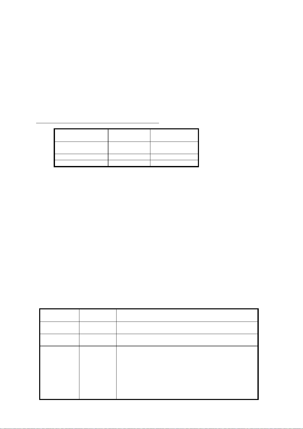
WIRING THE PRO-TEST TO DATA PROCESSORS:-
PRO-TEST
RS-232-C OUTPUT MITUTOYO
RS-232-C INPUT
CONNECTOR
COVER CABLE
SCREEN
PIN 3 PIN 3
PIN 5 PIN 7
For DP3DX & DP7 link pins 1 to 5 and 4 to 8 on Mitutoyo RS-232-C input.
For QM1000 & QM5000 link pins 4 to 5 and 6 to 8 on Mitutoyo RS-232-C input.
For more information please consult your Mitutoyo data processor manual.
MITUTOYO is a registered trade mark of Mitutoyo (UK) Ltd.
PRINT INHIBIT CONTROLLER OPTION
PART NUMBER 60167
INTRODUCTION :- _________________________________________________________________
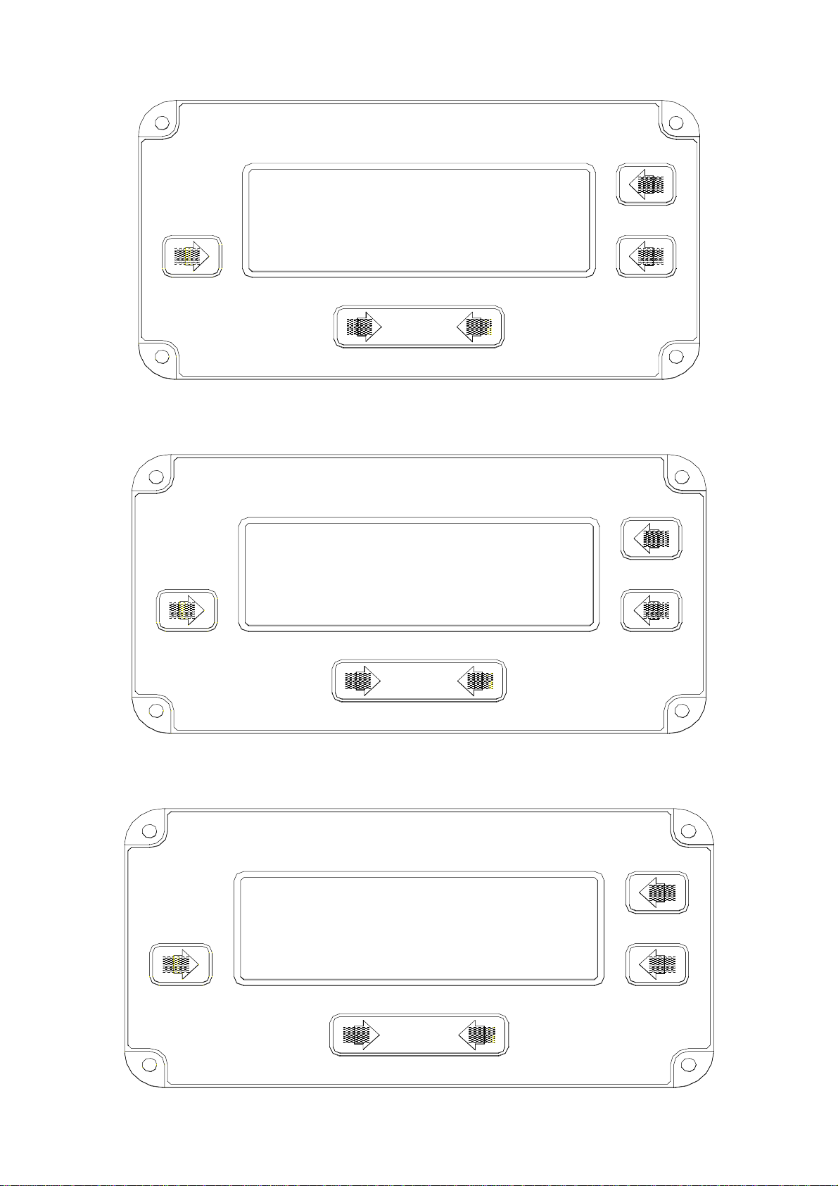
The print inhibit controller is a remote, hand held device for controlling the RS-232-C output from the
Pro-Test. This option can be retro fitted to any Pro-Test transducer, model numbers 43180-43183.
This option can control unwanted RS-232-C data input to printers, calibration and data collection
systems.
OPERATION :- ____________________________________________________________________
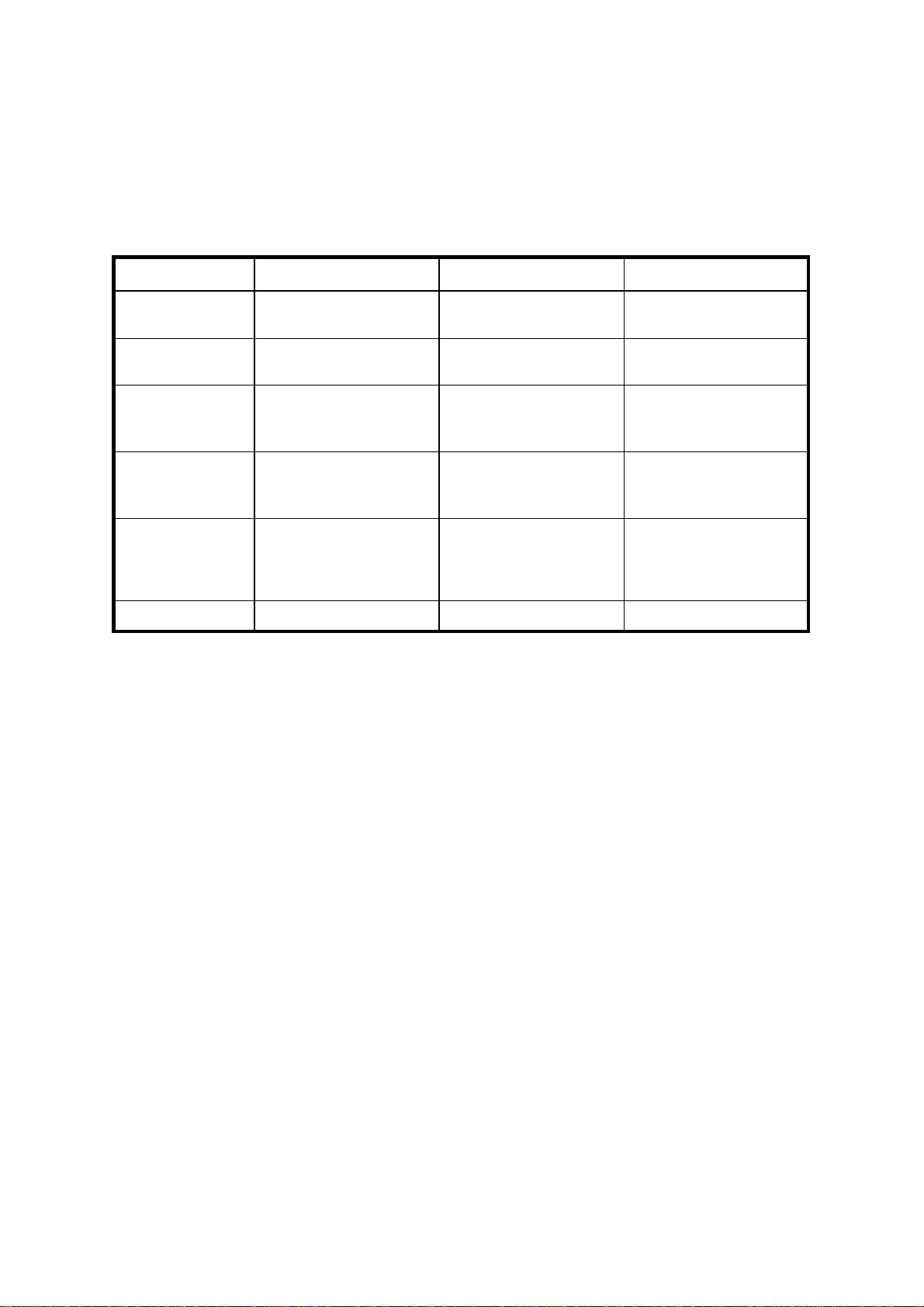
Position of ' PRINT NORMALLY/ PRINT WHEN ARMED’ switch :-
SWITCH
POSITION STATE OF
INDICATOR ACTION
'PRINT
NORMALLY' UNARMED The RS-232-C output acts as normal.
Every time an output is requested it will be issued.
'PRINT WHEN
ARMED’ UNARMED The RS-232-C output is inhibited, so will not function.
‘PRINT WHEN
ARMED’ ARMED
(Having
pressed
button on
controller)
When the ' ARM ' button is pressed, the arm led will light
so indicating that the next request to send data will be acted
upon.
Upon the next data output taking place, the arm led will turn
off and the RS-232-C output will again be inhibited.
To obtain further data output either press the ‘ARM’ button
or switch to ‘PRINT NORMALLY’.

PRO-TEST OPERATORS HANDBOOK PAGE 8 OF 10
ISSUE 4
AUGUST 1998
SPECIFICATIONS
PRO - TEST TRANSDUCER SPECIFICATION :- _________________________________________
PRO-TEST 40 PRO-TEST 400 PRO-TEST 1500ER
RANGE OF
OPERATION 0 to 40 N.m 0 to 400 N.m 0 to 1500 N.m
CALIBRATION
RANGE 5% to 100% of full scale.
2 to 40 N.m. 5% to 100% of full scale.
20 to 400 N.m. 2% to 100% of full scale.
30 to 1500 N.m.
TRANSDUCER
OVERLOAD
CAPACITY
150% of Pro-Test
calibration range
(60 N.m).
150% of Pro-Test
calibration range
(600 N.m).
150% of Pro-Test
calibration range
(2250 N.m).
DIMENSIONS
Height x Width
x Depth (mm) 106 x 106 x 185. 106 x 106 x 185. 106 x 106 x 185.
DRIVE
ADAPTERS 3/8’’ sq to 10 mm
hex socket
1/2’’ sq to 22 mm
hex socket
3/4’’ sq to 22 mm
hex socket
3/4’’ sq to 36 mm
hex socket
WEIGHT 3.9 kg (8.6 lb). 4.0 kg (8.9 lb). 4.9 kg (10.8 lb).
PRO-TEST DISPLAY UNIT SPECIFICATION :- __________________________________________
READOUT 240 x 64 pixel dot matrix display giving direction of
torque applied, 4 full digits, direct readout of
engineering units, stop loading indicator and front
panel button identification in all modes of operation
and set up menu’s.
DISPLAY UPDATE RATE 2 per second (2Hz).
RESOLUTION 1 Digit in 9999.
WEIGHT 2.4 kg (5.3 lb)
DIMENSIONS 128 mm high x 185 mm wide x 102 mm deep.

PRO-TEST OPERATORS HANDBOOK PAGE 9 OF 10
ISSUE 4
AUGUST 1998
SYSTEM SPECIFICATIONS :-________________________________________________________
ACCURACY +/-1% of reading over calibration range.
ZERO SUPPRESSION TRACK None.
ALL MEMORY MODES Suppressed from 0 to
approximately 0.5% of transducer calibration range.
UNITS OF MEASUREMENT PRO-TEST 40
N.m, dN.m, cN.m, lbf.ft, lbf.in, ozf.in,
kgf.m, kgf.cm. (Menu Selectable).
PRO-TEST 400
N.m, dN.m, lbf.ft, lbf.in,
kgf.m, kgf.cm. (Menu Selectable).
PRO-TEST 1500ER
N.m, lbf.ft, lbf.in, kgf.m. (Menu Selectable).
MEMORY AUTO-RESET TRIGGER 2.5%(High), 5%(Med), or 10%(Low) of reading
(Menu Selectable).
MEMORY AUTO RESET HOLD TIMES 1, 2, 3 or 4 seconds (Menu Selectable).
OPERATING TEMP RANGE +5°C to +40°C.
STORAGE TEMP RANGE -20°C to +70°C.
MAXIMUM OPERATING HUMIDITY 85% Relative Humidity @30°C.
POWER REQUIREMENTS 90 to 264 Volts AC at 50-60 Hz.
POWER CONSUMPTION 12.0 W - maximum.
POWER CABLE 2 meters (6 ft 6 ins) long minimum.
POWER PLUG FUSE (if fitted) 1 Amp
CASE MATERIALS / FINISH Display and Transducer housings engineered in
aluminium castings. Finished in powder coated paint.
ENVIRONMENT Indoor use within a light industrial environment.
ELECTROMAGNETIC COMPATIBILITY In conformance with EN 50081-1 : 1992
(EMC) DIRECTIVE & EN 50082-1 : 1992.
LOW VOLTAGE DIRECTIVE In conformance with EN 61010-1 : 1993.
To environmental conditions Pollution Degree 2
& Installation Category (Overvoltage Category) II.
TIME/DATE COMPLIANCE This equipment does not utilise time or date functions
and thus will not be affected by the issues of date
compliance in the future.
Due to continuous improvement all specifications are subject to change without prior notice.

PRO-TEST OPERATORS HANDBOOK PAGE 10 OF 10
ISSUE 4
AUGUST 1998
TROUBLE SHOOTING
1. No display when power is switched on.
a) Check the Power Supply Module is correctly plugged into the back of the transducer
housing.
b) Check fuse in mains power plug.
c) Check the lead is fitted between the display module and transducer.
2. Readings in First Peak mode are inconsistent.
Change First Peak sensitivity to be less sensitive, see SET-UP MENU section (page 4).
3. Required units of measurement are not selectable.
a) Conversion from transducer standard units to required units could not be displayed within
available digits on display, thus conversion is not allowed.
b) Units required have not been enabled. See SET-UP MENU section (page 4).
4. RS-232-C data output not communicating with other equipment.
a) Check that control word on the Pro-Test and the equipment receiving data match. See
page 6.
b) Check that the baud rate is set to 1200 baud on the equipment receiving data.
c) Check that the connecting lead is wired correctly at both ends, see page 6.
d) Check if equipment receiving data requires the units of measurement inhibited or a leading
character. This is applicable when interfacing to Mitutoyo equipment, see page 7.
5. Display shows zero and does not alter when torque applied.
Switch power off or disconnect at the mains power socket, wait 2 seconds, then power up the
Pro-Test again.
PRO-TEST CALIBRATION AND REPAIR :- _____________________________________________
To maintain the specified accuracy it is recommended that the Pro-Test transducers are recalibrated
at least once per year.
Recalibration and repair should be carried out at Norbar or by a Norbar approved agent, where all the
facilities to ensure the instrument is functioning at maximum accuracy are available.
Alternatively, procedures for calibrating the Pro-Test to the specified accuracy can be found in the
Professional Torque Tester (Pro-Test) service manual Part No. 34240.
CLEANING :-______________________________________________________________________
Do not use abrasives or solvent based cleaners. We recommend a propriety brand of foam based
fabric / vinyl cleaner. Use a soft cloth to avoid scratches.
This manual suits for next models
2
Table of contents
Other norbar Test Equipment manuals

norbar
norbar TWC 400 AUTO User manual

norbar
norbar 43228 User manual

norbar
norbar 80026 User manual

norbar
norbar TTT 3 Series Service manual

norbar
norbar TWL 1500 Service manual

norbar
norbar TWC Series User manual

norbar
norbar Pro-Test 60 SERIES 2 User manual

norbar
norbar 43222 User manual

norbar
norbar ISO 1500 User manual

norbar
norbar T-Box 43236 User manual