TTT SERIES 3 OPERATORS HANDBOOK PAGE 6OF 28
Issue 1
JANUARY 2006
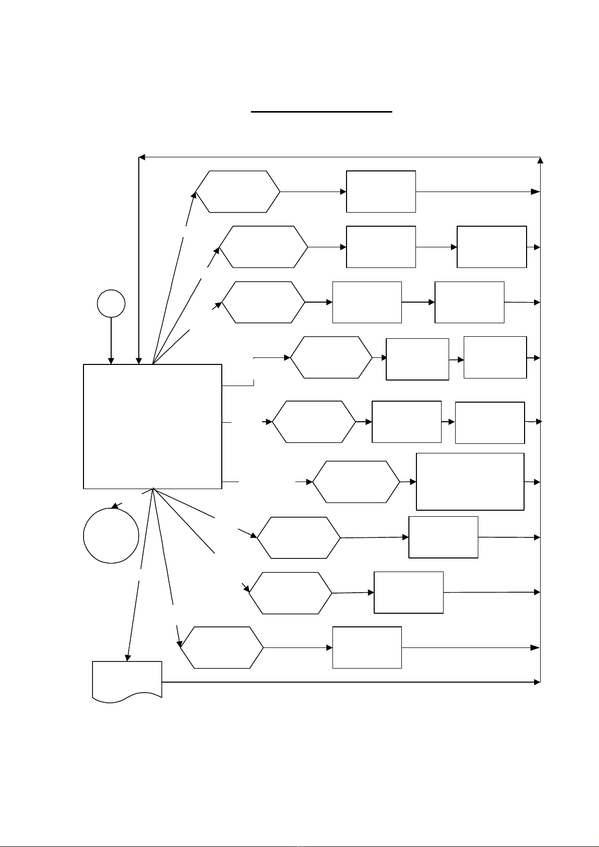
2. SETTINGS
Setting Options (defaults) Comment
LANGUAGE ENGLISH (default), FRANCAIS,
DEUTSCH, ITALIANO, ESPAÑOL,
DANSK, NEDERLANDS, SUOMI,
NORSK, SVENSKA, PORTUGUES.
Set language of operation.
PASSWORD Any 6 numeric characters
(default = ‘000000’).Set Password.
DATE & TIME Set date DD/MM/YY or MM/DD/YY.24 hour clock with date.
MODE
FREQUENCY 100Hz to 2500Hz (defaults, see
‘MODES OF MEASUREMENT’
section).
Select mode then select frequency from
list. OTHER FREQUENCY allows a
custom value.
SERIAL PORT See ‘SERIAL PORT’ section. Select required options.
THRESHOLDS FIRST PEAK SENSITIVITY =
LOW / MEDIUM / HIGH
(default = HIGH).
This is the amount by which the torque
must drop to register a first peak.
LOW must drop 10% of reading.
MEDIUM must drop 5% of reading.
HIGH must drop 2.5% of reading.
THRESHOLDS AUTO RESET HOLD TIME =
1 (default) / 2 / 3 / 4 seconds.The time allowed for automatic reset in
‘Click & Cam’ mode.
THRESHOLDS TRIGGER FROM =
0.5% to 99% of transducer capacity
(default = 1.8 %).
This is the point at which any memory
mode starts to work, all memory modes
will ‘TRACK’ below this setting. This
can help overcome false results.
Values entered below 0.5% will act as
0.5%.
THRESHOLDS PEAK MEMORY RESET =
AUTO /MANUAL (default). All Peak modes will reset the highest
reading automatically or manually.
UNITS All units (default = all enabled). Turn off unwanted torque units.
MODES All modes (default = all enabled). Turn off unwanted modes.
POWER DOWN
TIME 0 to 99 minutes (default = 10). The time before power down starts.
Set to ‘0’ to disable.
PRINT
SETTINGS None.All settings and limit settings can be
printed. No password is needed.
TIP: When ⇑or ⇓is shown on screen, this means more menu items are available.
For more information see flow diagram on page 9.
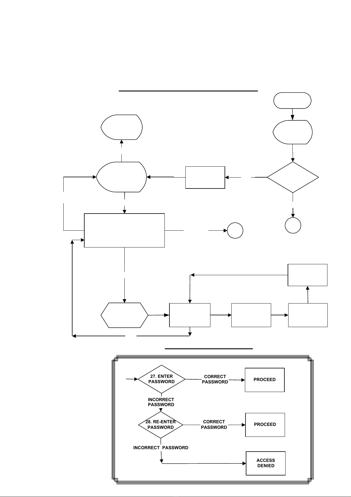
3. RETURN TO MEASURE
This option allows the user to view the measurement screen.
For ‘SMART’ transducers the measure screen is automatically entered.
For ‘NON-SMART’ transducers the option to store transducer details is available.
For more information see flow diagram on pages 7& 8.