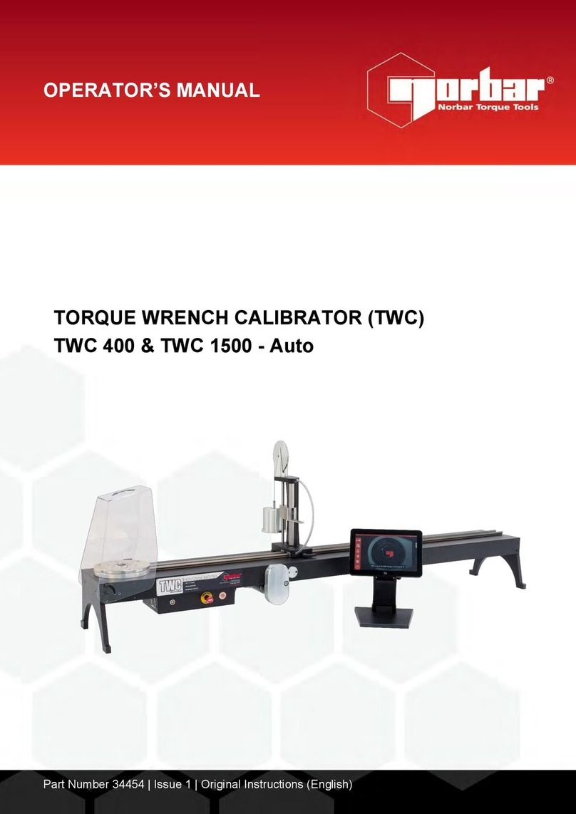
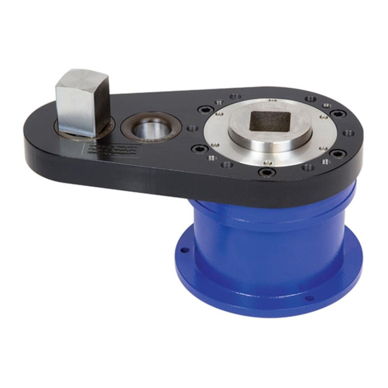
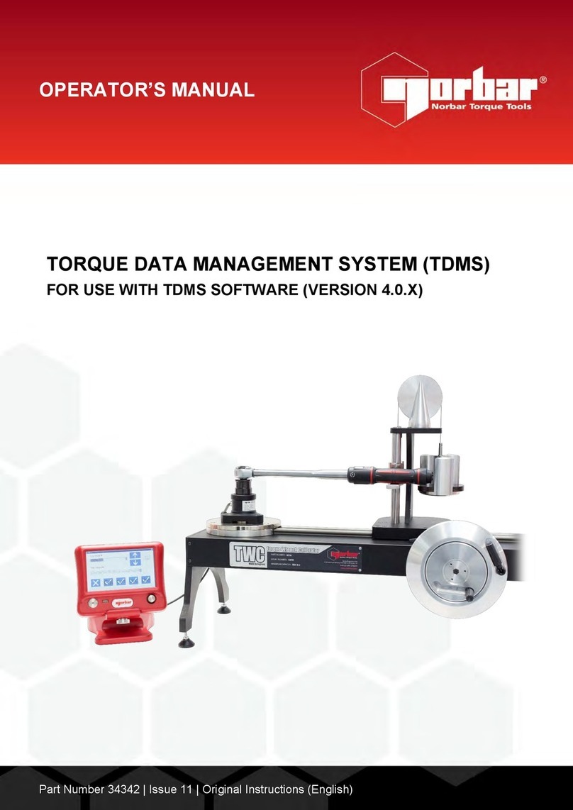
norbar TWL 1500 Service manual

TWL 1500
TORQUE WRENCH LOADER
OPERATOR’S HANDBOOK
(PART NUMBER 60246.1)
Issue 2
NORBAR TORQUE TOOLS
Unit 3/4 Adelaide Terrace
St Marys SA 5042
Australia
Tel: +61 (0)8 8374 3499
Fax: +61 (0)8 8374 2566
Website: www.norbar.com

PAGE 1 OF 8
Issue 2
JANUARY 2005
CONTENTS
PAGE
INTRODUCTION 2
SPECIFICATION 3
ITEMS SUPPLIED 3
AVAILABLE OPTIONS 3
ASSEMBLY INSTRUCTIONS
A. ASSEMBLY OF TRANSDUCER PLATE TO STAND 4
B. ASSEMBLY OF LOADING DEVICE TO STAND 4
C. ASSEMBLY OF THE DISPLAY STAND 5
D. ASSEMBLY OF FLANGE MOUNTED TRANSDUCERS 5
TO TRANSDUCER PLATE
E. ASSEMBLY OF PRO-TEST TRANSDUCER 6
F. ASSEMBLY OF “SMART” TORQUE BLOCK TRANSDUCER 7
OPERATING INSTRUCTIONS
MACHINE INSTALLATION 8
IMPORTANTNOTES 8
WRENCH INSTALLATION 8

PAGE 2 OF 8
Issue 2
JANUARY 2005
INTRODUCTION
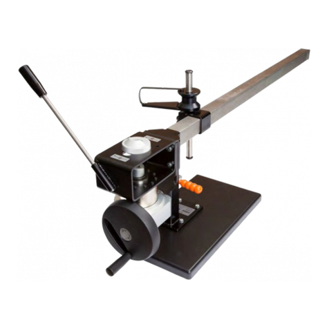
This handbook covers Torque Wrench Loader TWL 1500 (Part No. 60246).
The Norbar TWL1500 Torque Wrench Loader is designed to test torque wrenches up
to a maximum capacity of 1500 N.m.
Any torque wrench within the systems maximum capacity can be tested in the
horizontal plane to their appropriate standard.
To measure the applied torque a torque transducer coupled to an appropriate display
instrument are required.
The TWL1500 can be equipped with a:-
- Selection of 5 Flange Mounted Transducers from 10 Nm to 1500 N.m Capacity.
(Part No’s. 50672.LOG to 50676.LOG)
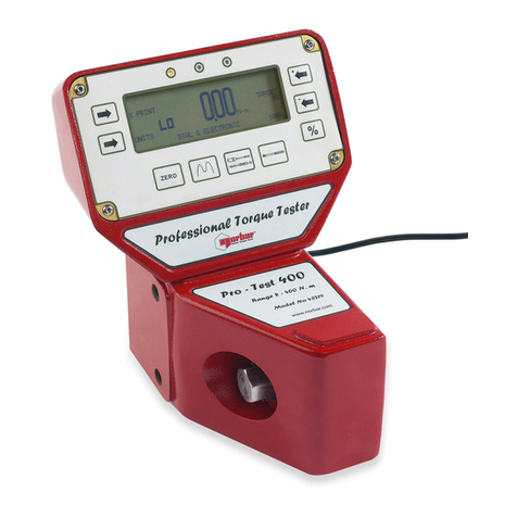
- Pro-Test Transducer of 400 N.m Capacity. (Part No. 43181)
- Pro-Test Transducer of 1500 N.m Capacity. (Part No. 43189)
-“SMART” Torque Block Transducer of 1000 N.m Capacity. (Part No.50683.LOG)

PAGE 3 OF 8
Issue 2
JANUARY 2005
SPECIFICATION
MIN OUTPUT TORQUE- 1 N.m
MAX OUTPUT TORQUE- 1500 N.m
WRENCH ORIENTATION- Horizontal
CALIBRATION DIRECTION - Clockwise and Anti-Clockwise
DIMENSIONS
Width 730 mm
Length 1720 mm
Height 345 mm
WEIGHT 32 kg (70.5 lb)
ITEMS SUPPLIED
STAND
FRAME ASSEMBLY BOLT KIT
TRANSDUCER PLATE
LOADING DEVICE ASSEMBLY
DISPLAY STAND
DISPLAY STAND BASE
DISPLAY SUPPORT ARM
DISPLAY STAND BOLT KIT
FLANGE MOUNTED TRANSDUCER SPACERS (2 OFF)
FLANGE MOUNTED TRANSDUCER BOLT KIT
PRO-TEST ADAPTOR PLATE
“SMART” TORQUE BLOCK BOLT KIT
AVAILABLE OPTIONS
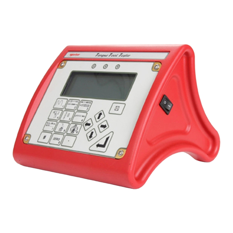
i. Norbar Torque Tool Tester display instrument (part no.43215) and Flange
Mounted Transducers (part no’s. 50672.LOG to 50676.LOG)
ii. Norbar Torque Tool Tester display instrument (part no.43215) and STB1000
“SMART” Torque Block .(part no.50683.LOG)
iii. 400 Pro-Test transducer (part no. 43181) and display (part no. 43184)
iv. 1500ER Pro-Test transducer (part no. 43189) and display (part no.43184)

PAGE 4 OF 8
Issue 2
JANUARY 2005
LOADING DEVICE
ASSEMBLY INSTRUCTIONS
A. ASSEMBLY OF TRANSDUCER PLATE TO STAND
1) Align flanges of transducer plate and use the frame assembly bolt kit (M10 bolts,
washers and nuts) to fasten.
2) Tighten bolts to 20 N.m.
B. ASSEMBLY OF LOADING DEVICE TO STAND
1) Remove the 2 thumb screws and the clamp plate from the loading device.
2) Position the loading device onto the stand ensuring that the hand wheel is on the
side of the operator
3) Reconnect the clamp plate using the 2 thumb screws and tighten in the desired
position along the stand.
4) Screw the handle to the hand wheel and tighten the locknut
5) Slide the support bobbin onto the reaction post
STAND
TRANSDUCER
PLATE
SUPPORT
BOBBIN HAND WHEEL
THUMB
SCREWS
CLAMP PLATE
HANDLE

PAGE 5 OF 8
Issue 2
JANUARY 2005
C. ASSEMBLY OF THE DISPLAY STAND
1) Screw the display stand to the display stand base using 2 off M5x16mm long
screws.
2) Insert the display stand base into the display support arm and tighten using the
thumb nut from the display stand bolt kit.
3) Attach the support arm to the transducer plate and fasten using the M10x50mm
long screw and thumb nut from the display stand bolt kit.
D. ASSEMBLY OF FLANGE MOUNTED TRANSDUCERS TO TRANSDUCER
PLATE.
1) Place the spacers for the smaller transducers in the position shown below.
2) Attach the transducers to the transducer plate in the positions shown below using
the bolts supplied in the flange mounted transducer bolt kit. Tighten the
M5x75 bolts to 5Nm, the M8x60 bolts to 10Nm and the M12x30 bolts to 15Nm.
3) Ensure that the cables are extending out to the display stand side of the unit.
4) Connect the transducer lead to the Torque Tool Tester display instrument and
mount it on the display stand. Connect the power supply to the Torque Tool
Tester.
DISPLAY
SUPPORT
ARM
DISPLAY
STAND
DISPLAY
STAND
BASE
M5
SCREWS
M10
SCREW
THUMB
NUTS
SPACERS
FMT1500
FMT150
FMT400
FMT10
FMT25

PAGE 6 OF 8
Issue 2
JANUARY 2005
E. ASSEMBLY OF PRO-TEST TRANSDUCER
1) Place the Pro-Test adaptor plate in the position shown below.
2) Fasten the Pro-Test adaptor plate to the transducer plate using the 3 off
M12x30mm long bolts from the flange mounted transducer bolt kit.
Tighten to 15 N.m.
3) Fasten the Pro-Test Transducer to the adaptor plate in one of the two mounting
positions using the shoulder bolts provided with the Pro-Test.
4) It is recommended that the Pro Test 1500ER Transducer be fastened to the
furthermost position from the loading device. The Pro-Test 400 Transducer is to
be fastened to the closest position to the loading device.
5) Mount the Pro-Test Display unit on top of the Pro-Test and connect to the
transducer.
6) Connect the power supply to the Pro-Test unit
PRO-TEST
ADAPTOR
PLATE
M12 BOLT
TRANSDUCER
PLATE
M12 BOLT
IMPORTANT ! Bolts must be Torque Tightened to 50 N.m. and replaced
when removed. Refer to Pro-Test Operator’s Handbook.

PAGE 7 OF 8
Issue 2
JANUARY 2005
F. ASSEMBLY OF “SMART” TORQUE BLOCK TRANSDUCER
1) Attach the “SMART” Torque Block directly to the transducer plate using the 4 off
M8x25mm long bolts from the “SMART” Torque Block bolt kit. There are two
mounting positions to choose from on the transducer plate shown below.
2) It is recommended that the “SMART” Torque Block be mounted in the furthermost
position from the loading device, unless it is deemed necessary to mount it closer
to the loading device due to the length of the torque wrench being tested.
3) Tighten bolts to 42Nm.
4) Connect the “Smart” Torque Block transducer lead to the Torque Tool Tester
display instrument and mount it on the display stand.
5) Connect the power supply to the Torque Tool Tester.
ALTERNATE
MOUNTING
POSITIONS

PAGE 8 OF 8
Issue 2
JANUARY 2005
OPERATING INSTRUCTIONS
MACHINE INSTALLATION
Secure the TWL 1500 onto a sturdy bench making sure there is enough room
around the unit for the display stand and for the loading device to move freely along
the length of the stand.
IMPORTANT NOTES
a. Ensure that the bolts fastening the transducer plate to the stand are torque
tightened to 20 N.m.
b. Always ensure loading device is firmly clamped before loading the rig.
c. Always ensure the transducer leads are not caught up in the mechanism.
d. To ensure trouble free use, periodically check that the screw thread and guide
rails on the loading device are lubricated with a good quality machine oil.
WRENCH INSTALLATION
1. Slide the loading device assembly along the reaction bar far enough to allow
clearance for the torque wrench to be installed in the TWL1500.
2. Select the lowest capacity torque transducer to cover the wrench to be tested.
3. With the handle of the wrench running along the length of the reaction bar, mount
the torque wrench to be tested in the female square drive of the selected torque
transducer.
4. Slide the loading device assembly along the reaction bar so that the support bobbin
is reacting against the normal hand position of the wrench. This is usually the
centre of the wrench hand grip.
5. If the wrench is fitted with a square drive ratchet ensure that the orientation of the
square drive allows maximum travel of the wrench handle by the support bobbin.
6. Orientate the support bobbin so that the wrench maintains a horizontal position
during testing.
7. Firmly tighten the clamp plate of the loading device before loading the rig.
8. Turn the hand-wheel smoothly to apply load to the torque wrench.
9. Follow the appropriate calibration procedures for the torque wrench being tested.
NOTE: In the case of a ratchet wrench with push through square drives, it is
important to ensure the square is operating on the correct side of the
ratchet.
Table of contents
Other norbar Test Equipment manuals

norbar
norbar PRO-TEST 40 Service manual

norbar
norbar 43228 User manual

norbar
norbar 43222 User manual

norbar
norbar ISO 1500 User manual

norbar
norbar TTT 3 Series Service manual

norbar
norbar T-Box 43236 User manual

norbar
norbar TWC Series User manual

norbar
norbar 80026 User manual

norbar
norbar Pro-Test 60 SERIES 2 User manual

norbar
norbar TWC 400 AUTO User manual