See−Flo 7 Dispenser
6
Part 7446077 2020 Nordson Corporation
Theory Of Operation
Dispenser
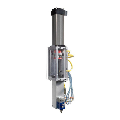
An air cylinder is attached to the free end of a fulcrum bar. The opposite end of the fulcrum bar is attached to
a pivot. Both the air cylinder and the pivot end of the fulcrum bar are mounted to the frame. As the air
cylinder is caused to reciprocate (by the system’s controls), the free end of the fulcrum bar is caused to
travel through an arc. Metering cylinders are mounted to the frame, with their metering rods attached to the
fulcrum bar. As the fulcrum bar reciprocates, so do the metering rods of the metering cylinders, causing
pumping action to occur within the metering cylinder.
One of the metering cylinders is positioned directly below the air cylinder. This metering cylinder is allowed to
stroke its’ full length. The second metering cylinder is positioned at a point between the first metering
cylinder and the pivot point at the fixed end of the fulcrum bar. With the fulcrum bar in place, the second
metering cylinder is limited to less stroke than the first metering cylinder. The point at which the second
metering cylinder is located is variable and allows manipulation of the stroke length. This affects the ratio of
displacement of one metering cylinder to the other. Manipulating the selection of metering cylinders, based
upon the displacement of metering cylinders, allows different ratios to be selected.
Bulk process fluids (generally a resin and a catalyst) are delivered to the meter. If the material are low
enough in viscosity, they may be delivered to the dispenser via a gravity feed arrangement, from a bulk
container, or other device. Medium viscosity materials may be delivered to the meter through the use of a
pressure vessel. Still higher viscosity fluids may require the use of a pump to supply the meter. Several
styles of pumps are available including pail, drum, ram type, and diaphragm.
The two metered fluids exit the outlet ports of the metering cylinders as the system reciprocates. These
metered fluids are conveyed through hoses, fittings, piping, and in some instances through power operated
fluid handling valves to other devices integral to the system such as dual dispense valves and disposable
static mixers, dynamic power mixers, mix manifolds, static mixers, single fluid dispense valves, ratio check
assemblies, and shot metering devices to deliver the metered/mixed/dispensed fluids to the point of
application.
Metering Cylinder
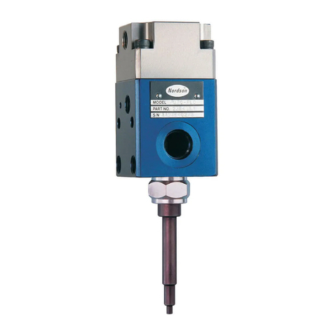
The double acting, balanced metering cylinder is a precision pump of the reciprocating type. These metering
cylinders are available in several styles and displacement ranges. The metering cylinder consists of a
cylinder, a piston with an internal check valve which is attached to a metering rod, a check valve (foot valve)
located at the inlet end of the cylinder, piston seal(s), rod seal(s), rod bearing(s), and a packing nut to retain
the rod seals and bearing. Double acting refers to the ability of the metering cylinder to meter fluid in both
directions. Balanced refers to equal amounts of fluid displaced during each direction of stroke.
As the metering rod is retracted from the metering cylinder, the check valve within the piston closes due to
the pressure differential within the metering cylinder. The fluid volume above the metering cylinder is
decreasing, creating a flow of fluid to the discharge port. At the same time a pressure differential across the
foot valve causes it to open. This allows fluid to flow from the supply source to the increased volumetric area
above the foot valve and below the piston.
As the metering rod is extended into the metering cylinder, the foot valve closes and the piston check valve
opens due to the pressure differential within the metering cylinder. The fluid volume below the piston
decreases and material passes through the piston check valve into the cavity of the metering cylinder above
the piston. The volume of fluid displaced from the lower portion of the cylinder during the extension cycle is
twice the volume being created in the upper portion of the metering cylinder. As a result, half of the fluid
refills the upper cavity and the other half exits the discharge port of the metering cylinder.

