manuals.online logo
Brands
  1. Home
  2. •
  3. Brands
  4. •
  5. Norton
  6. •
  7. Door Opening System
  8. •
  9. Norton 8380 User manual

Norton 8380 User manual

8180 Series
Non Hold Open Door Closers
Models 8180
8380
8580
CAUTION
CAUTION
AN INCORRECTLY INSTALLED OR IMPROPERLY ADJUSTED
DOOR CLOSER CAN CAUSE PROPERTY DAMAGE OR
PERSONAL INJURY. THESE INSTALLATION INSTRUCTIONS
SHOULD BE FOLLOWED TO AVOID THE POSSIBILITY OF
MISAPPLICATION OR MISADJUSTMENT.
Installation Instructions
80-9380-0207-020 (10-02)
For Special Applications a separate door and frame preparation template is packed with these instructions.
Use this instruction sheet for installation sequence and closer adjustments only.
Note:
Closer mounts on hinge (pull) side of door
See Page 2
Regular Arm Installation
Right Hand Door - RH
Left Hand Reverse - LHR
Left Hand Door - LH
Right Hand Reverse - RHR
Right Hand Door - RH
Left Hand Reverse - LHR
Left Hand Door - LH
Right Hand Reverse - RHR
Parallel Arm Installation
Closer mounts on opposite to hinge (push) side of door
See Page 3
Closer Components:
1618A Parallel
Arm Bracket
Screw Pack
Backcheck Valve
Latch Valve
Sweep Valve
Closer Body
Standard 8380 Narrow Cover
Pinion Cap
Insert Cutouts
Cover
Insert
Standard 8580 Full Cover
Cover Clips
Cover Screw
Cover Screws
Optional 8580 Metal Cover
Cover Screw
Cover Screws
Optional 8580 Architectural Metal Cover
Standoffs
Insert Cutouts
Cover
Insert
Optional 8580 Architectural Plastic Full Cover
Standoff
Standoff
Closer Arm Elbow
Screw
Main Arm
Regular Arm/Top
Jamb Shoe
Forearm
Forearm Screw
Connecting Rod
Spring Adjustment Shaft
Page 2
Installation
Instructions Regular Arm
Hinge or Pivot
12
(304.8)
5-1/2
(140)
1-3/4
(44.4)
Hinge Edge of Door
A
3/4
(19.1)
Closer Pinion
1/4-20 Machine Screws or
#14 Wood Screws (6 holes)
Ref
Min to Ceiling
1
(25)
2-1/2
(64)
Opening inches mm.
A
To 100° 7-1/2 191
100° to 130° 6152
Over 130° 4-1/2 114
Right Hand Door
90° 90°
Left Hand Door
Figure 1
• Select door opening sing template
dimensions mark for closer
and 2 for arm shoe.
• Prepare for fasteners –
See "Fasteners Chart", this page.
• Remove forearm screw from arm assembly and
fasten the arm show assembly to the frame
face. (Slot facing down.)
• Mount closer body to door. Place end with
of door.
NOTE: If using full metal cover, cover mounting
clips must be slipped under ends of closer
when closer is being mounted.
• Install main arm on top of pinion shaft. Align the
with the letter (See Figure 1).
Fasten with arm screw.
• Reassemble Arm Adjust forearm perpendicular
to door (90
• Adjust closer. See page 4.
• Install Pinion Cap and/or Cover. See page 4.
angle. U
4 holes on door
holes on frame
2
regulating valves toward hinge edge
pinion flat "S"
° angle). Tighten set screw.
1 1/4
(32)
1/2
(13)
4
(101.6)
4
(101.6)
Prepare these holes when
8148 Drop Plate is used
5/16
(7.9)
L
R
Y
S
Z
Pinion Flat Arm Mark
9/32” (7 mm);
3/8” (9.5 mm) dia. x
3/8” (9.5 mm) deep on
door opposite to closer
Standard
Optional
Through-bolts and
grommet-nuts
All
Preparation for Fasteners
Door or Frame
Fasteners Drill-Sizes
Self-Drilling Screw
Wood 3/16” (4.30 mm)
1/4” - 20 machine screw Metal Drill: #7 (0.201” dia.)
Tap: 1/4” - 20
Sleeve nuts and bolts
Hollow
Metal
9/32” (7 mm) through;
3/8” (9.5 mm) door face
opposite to closer
Aluminum
or Wood 3/8” (9.5 mm) through
Aluminum
or Metal No drill required
Page 3
80-9380-0207-020 (10-02)
3/8
(9.5)
A
2
(50.8)
2-3/4
(69.8)
5/16
(8)
7/16
(11.1)
12
(304.8)
2-7/8
(73)
3/4
(19.1)
5/16
(7.9)
L
R
Y
S
Z
L
R
Y
S
Z
Installation
Instructions
Pinion Flat
Pinion Flat
Right Hand Door
Left Hand Door
Hinge Edge of Door
1-1/2
(38)
Arm Mark Arm Mark
• Select door opening sing template
dimensions mark for closer
body (or for drop plate) and
for soffit plate.
• Prepare for fasteners –
See "Fasteners Chart", page 2.
• Mount soffit plate to frame.
• Mount closer body to door (or mount drop plate
to door and then the closer body to the plate).
Place end with
of door.
NOTE: If using full metal cover, cover mounting
clips must be slipped under ends of closer
when closer is being mounted.
• Install main arm on top of pinion shaft. Rotate
pinion 45° toward hinge edge of door and align
the with arm mark:
for left hand door
for right hand door
(See figure 2) Fasten with arm screw
• Fasten arm tube to soffit plate with soffit plate
screw.
• Assemble arm. Open door slightly and insert
rod into arm tube. Close door and adjust
forearm length so that the
. Fasten to main
arm with forearm screw.
• Adjust Closer – See Page 4.
• Install Pinion Cap and/or Cover. See Page 4.
Architectural Covers CAN NOT be
used for doors swinging over 120
angle. U
4 holes on door
4 holes on frame
soffit
2 regulating valves toward
lock edge
pinion flat
"2"
"3"
arm elbow is 1-1/2"
(38mm) from door surface
NOTE:
° using
parallel mount.
Parallel Arm
Hinge or Pivot
4
(101.6) 4
(101.6)
1
(25)
Prepare these holes when
8148 Drop Plate is used 1/4-20 Machine Screws or
#14 Wood Screws (4 holes)
Figure 2
1/4-20 Machine Screws or
#14 Wood Screws (4 Holes)
Soffit Plate
Forearm
Main Arm
Opening
Dim A Dim B
To 120° 9-1/2
inches inchesmm mm
3-3/4
241 95
Over 120° 7 1-1/4
178 32
Page 4
Arm Placement in Shoe
or
or
7-1/2 % Stronger
7-1/2 % Weaker
LS
L
A
T
C
H
L
A
T
C
H
O
P
E
N
I
N
G
Delayed Action
Closing Cycle
3B
Closing Speed Controls Figure 3.
S
W
E
E
P
CLOSED
CLOSED
S
W
E
E
P
Standard
Closing Cycle
3A
D
E
L
A
Y
R
A
N
G
E
10°
10°
70°
CAUTION:
DO NOT BACK VALVES OUT OF CLOSER
OR A LEAK WILL RESULT.
CAUTION:
DO NOT BACK VALVES OUT OF CLOSER
OR A LEAK WILL RESULT.
Closing Speed Controls Figure 4.
Slow
Slow
Slow
1/8"
Hex
Key
1/8"
Hex
Key
1/8"
Hex
Key
1/8"
Hex
Key
Fast
Fast
Fast
Latch
Valve
Sweep
Valve
Delay Valve
Decrease
Increase
Opening Door Control Figure 5.
Opening Cycle
B
A
C
K
C
H
E
C
K
Backcheck Control Figure 6.
Backcheck Valve*
* NEVER close this valve completely.
Control Valve Adjustments
Closing Speed Controls (Figure 4.)
(see Figure 3.)
• Valve "S" Controls Sweep Range.
• Valve "L" Controls Latch Range.
• Valve "D" Controls Delay Range.
Optional for all models.
Opening Cycle
•"Backcheck" valve controls the strength of cushioning in
Backcheck Range. NEVER close this valve completely – it is not
to provide a positive stop. (see Figure 5 and Figure 6).
Unit Adjustment
Cover
Full cover: Slide cover insert into the un-used cutout in cover. Install
cover using screws provided.
Narrow cover: Install cover using screws provided. Install pinion cap
onto pinion shaft by hand or with a Phillips screw driver - DO NOT
OVER TIGHTEN.
Full metal cover: Fasten cover to mounting clips with screws provided.
Architectural Metal Cover: Remove cover insert where pinion is
located. Install standoffs in ends of closer. Install cover using screws
provided.
Architectural Plastic Cover: Slide cover insert into the un-used cutout
in cover. Install standoffs in ends of closer. Snap cover over standoffs.
1902 Airport Road, Monroe, NC
Telephone:(800)-438-1951; Fax: (800)-338-0965
www.nortondoorcontrols.com
Door Controls
An ASSA ABLOY Group Co.

This manual suits for next models

2

Other Norton Door Opening System manuals
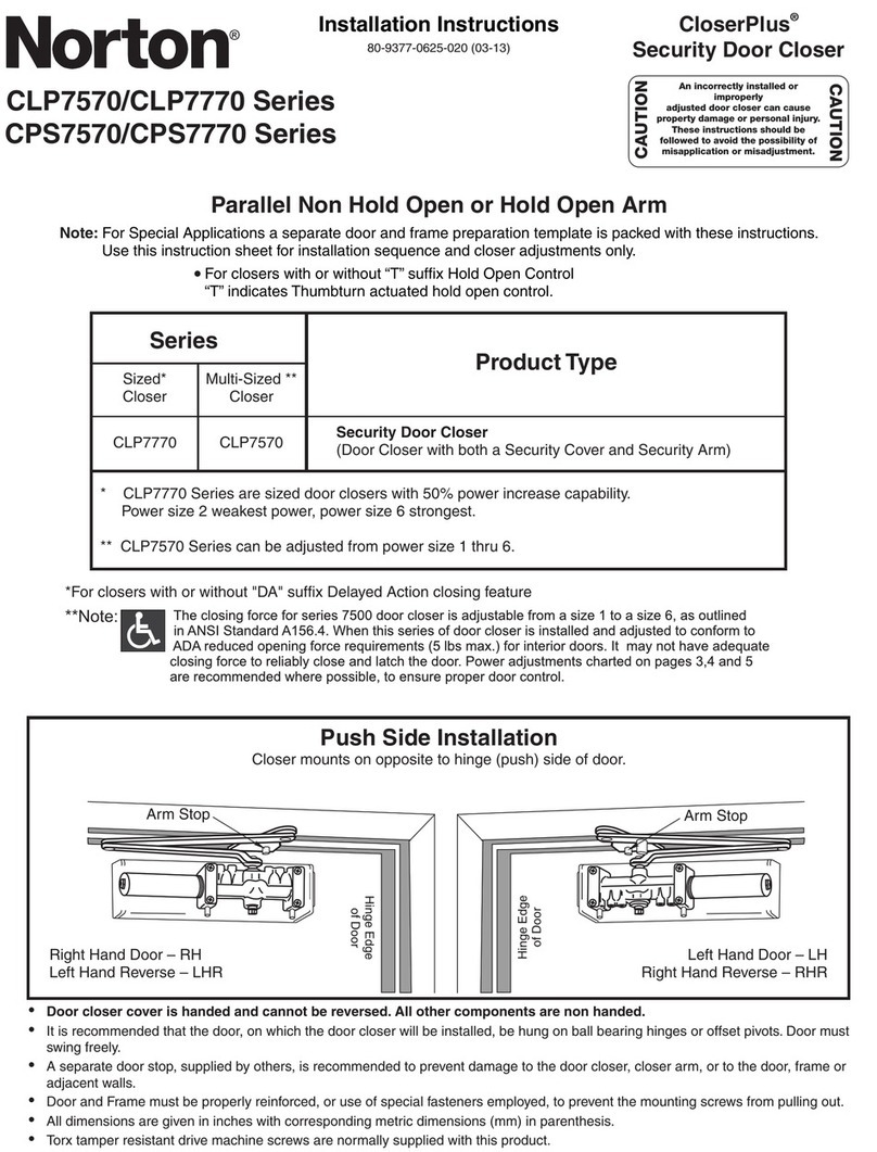
Norton 6900 PowerMatic User manual

Norton

Norton 6900 PowerMatic User manual

Norton Tri-Style 1600 Series User manual

Norton

Norton Tri-Style 1600 Series User manual

Norton 8000 Series User manual

Norton

Norton 8000 Series User manual

Norton Assa Abloy D6001DE-L Series User manual

Norton

Norton Assa Abloy D6001DE-L Series User manual

Norton LEO 5710 Series User manual

Norton

Norton LEO 5710 Series User manual

Norton 1600 Series User manual

Norton

Norton 1600 Series User manual

Norton Power Track Series User manual

Norton

Norton Power Track Series User manual

Norton tri-style 1603BC User manual

Norton

Norton tri-style 1603BC User manual

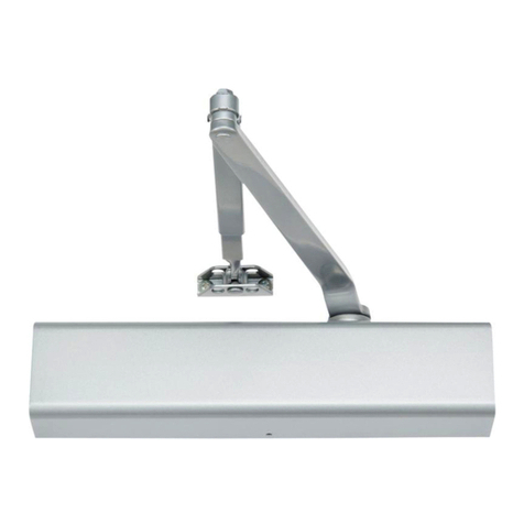
Norton CloserPlus CLP7570 Series User manual
Norton

Norton CloserPlus CLP7570 Series User manual

Norton Power Track Master Unit PTD Series User manual

Norton

Norton Power Track Master Unit PTD Series User manual

Norton PR7570 Series User manual

Norton

Norton PR7570 Series User manual
Popular Door Opening System manuals by other brands

SOMFY Yslo Flex 2 RTS installation guide

SOMFY

SOMFY Yslo Flex 2 RTS installation guide

Yale PR3301 installation instructions

Yale

Yale PR3301 installation instructions

CAME MI1010 quick start guide

CAME

CAME MI1010 quick start guide

Fireco Dorgard X2 Fitting and Operating Guide

Fireco

Fireco Dorgard X2 Fitting and Operating Guide

GEZE TSA 160 NT Series Wiring diagram

GEZE

GEZE TSA 160 NT Series Wiring diagram

GAL MOM How to connect

GAL

GAL MOM How to connect

Iseo ACE IS9100 Mounting instructions

Iseo

Iseo ACE IS9100 Mounting instructions

Locinox LION manual

Locinox

Locinox LION manual

GILGEN FDC-B France Operator's manual

GILGEN

GILGEN FDC-B France Operator's manual

Rixson DE 6 PULL installation instructions

Rixson

Rixson DE 6 PULL installation instructions

Dormakaba ED50 owner's manual

Dormakaba

Dormakaba ED50 owner's manual

GEZE Levolan 120 manual

GEZE

GEZE Levolan 120 manual

Automatic Technology DOMINATOR ShedMaster GDO-8V3 instruction manual

Automatic Technology

Automatic Technology DOMINATOR ShedMaster GDO-8V3 instruction manual

PDQ 3100 instruction sheet

PDQ

PDQ 3100 instruction sheet

Bohle Juna instruction manual

Bohle

Bohle Juna instruction manual

Record STA20 Retrofit Guide

Record

Record STA20 Retrofit Guide

KROME 910DA installation instructions

KROME

KROME 910DA installation instructions

Lamp FD50-H installation manual

Lamp

Lamp FD50-H installation manual

manuals.online logo
manuals.online logoBrands
  • About & Mission
  • Contact us
  • Privacy Policy
  • Terms and Conditions

Copyright 2025 Manuals.Online. All Rights Reserved.