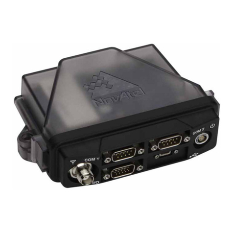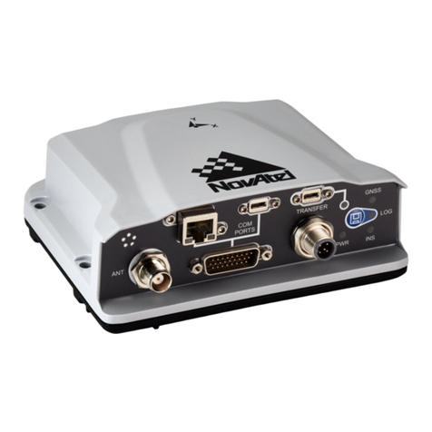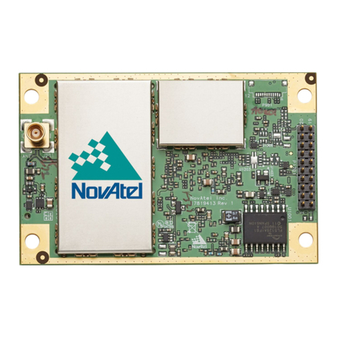
Installation & Powering Steps
1. Connect the antenna and oscillator cables using the TNC/BNC end of the coaxial cable.
2. Connect the event end cable to applicable EVENT connector.
3. Set external power supply to 9 V to 36 V.
4. Connect any communications equipment to be used.
5. Connect power cord and plug into external power supply.
LED Stack: Status LED States
Left LED Stack from Top Right LED Stack from Top
LED# Description Color LED# Description Color
6n/a 7n/a
4n/a 5n/a
2n/a 3POS_VALID GREEN
0ERROR RED 1POWER RED
CAN Ports DB9, Female (x2)
PIN# CAN0 CAN1
1 NC NC
2CAN_L CAN_L
3GND GND
4 NC NC
5GND GND
6GND GND
7CAN_H CAN_H
8 NC NC
9 12 V CAN power 12 V CAN power
COM Ports DB9, Male (x3 Active)
PIN# COM1 COM2 COM3
1 NC NC NC
2RXD1 RXD2 RXD
3 TXD1 TXD2 TXD
4 NC NC NC
5GND GND GND
6NC NC NC
7 RTS1 RTS2 NC
8 CTS1 CTS2 NC
9 NC NC NC
COM4 and COM5 are not active. Future use.
Antenna and External Oscillator
TNC GNSS
Antenna
Antenna Selection
Install a quality GNSS antenna in a location with
an unobstructed view of the sky.
BNC
OSC
(External
Oscillator)
External Oscillator
Some applications require greater precision than
that possible with the OEM7 VCTCXO, in which
case you may need to connect the OEM7 to an
external high-stability oscillator, which may run at
either 5 MHz or 10 MHz.
Contact NovAtel Customer Support
Log a support request with NovAtel Customer Support using one of the following methods:
Log a Case and Search Knowledge: Website: www.novatel.com/support
Log a Case, Search Knowledge and View Your Case History (login access required):
Web Portal: https://novatelsupport.force.com/community/login
Telephone: U.S. and Canada: 1-800-NOVATEL (1-800-668-2835) International: +1-403-295-4900
Federal Communications Commission (FCC) and Innovation, Science and Economic Development (ISED) Canada
This equipment has been tested and found to comply with the limits for a Class A digital device, pursuant to Part 15 of FCC Rules. These limits are
designed to provide reasonable protection against harmful interference when the equipment is operated in a commercial environment. This equip-
ment generates, uses and can radiate radio frequency energy and, if not installed and used in accordance with this instruction manual may cause
harmful interference to radio communications. Operation of this equipment in a residential area is likely to cause harmful interference in which
case the user will be required to correct the interference at their own expense.
COM1
EVENT
IN 1
EVENT
IN 2
EVENT
OUT 1
EVENT
OUT 2
COM2
COM3
RESET
EXT. OSC ANTENNA
STATUS
ETHERNET
USB1 USB0
COM4 COM5 CAN1
POWER
(9-36 VDC)
CAN0
EVENT Ports
2 Position, 50 Ohm BNC, 1 GHz Max (X4)
NOTE: EVENT OUT 1 & EVENT IN 2 not active.
Reset Button
Press to perform
reset of receiver RJ45
10/100 Base-T
USB0 Device Micro-AB
NOTE: USB1 is not active. Future use.
TNC
BNC
Green LED
Link/Activity
Yellow LED
Not used
LED Stack
6
4
2
0
7
5
3
1
COM Ports
DB9, Male Active: COM 1, 2 and 3
NOTE: COM 4 and COM5 are not active. Future use.
CAN Ports
DB9, Female (X2)
LED Stack Legend
Refer to Table
