Novy Pureline Frame 15001 User manual

NL Installatievoorschriften 3
FR
Instructions
d’installation 4
DE Montageanleitung 6
EN Operating and installation Instructions 7
15001 110540 MA1
Novy Pureline Frame
15001 / 15002 / 15003 / 15004 /
15005 / 15006 / 15007 / 15008 /
15009 / 15010 / 15011 / 15012


3
NL
1 VOORSCHRIFTEN VOOR VEILIGHEID
EN MONTAGE
Meer informatie over de Novy producten, accessoires
en diensten kunt u vinden op internet: www.novy.be.
Dit is de montage instructie voor het toestel zoals op de
voorzijde is aangegeven. De gebruiksaanwijzing is een
apart boekje dat met het toestel is meegeleverd.
In deze montage instructie wordt gewerkt met een aan-
tal symbolen. Hieronder vind u de betekenis van deze
symbolen.
Symbool Betekenis Actie
Indicatie Toelichting van een
indicatie op de afzuigkap.
Info/
Waarschuwing
Dit symbool duidt op
een belangrijke tip of een
gevaarlijke situatie
Leef deze instructie na om letsel en materiële schade
te voorkomen.
Waarschuwingen voorafgaand montage
− Dit toestel voldoet aan de geldende veiligheidsvoor-
schriften. Ondeskundige montage kan echter persoonlijk
letsel en schade aan het toestel veroorzaken.
−
Het toestel is uitsluitend bedoeld voor huishoudelijk
gebruik (bereiding van voedingsmiddelen) met uitsluiting
van alle ander huishoudelijk, commercieel of industrieel
gebruik. Gebruik het toestel niet buitenshuis.
− Controleer de staat van het toestel en het montage-
materiaal zodra u ze uit de verpakking haalt. Neem
het toestel met zorg uit de verpakking. Gebruik geen
scherpe messen om de verpakking te openen.
− Installeer het toestel niet indien het beschadigd is en
richt u in dat geval tot Novy.
− Controleer aan de hand van tekening A of alle mon-
tagematerialen meegeleverd zijn. De vetlters bevinden
zich in het toestel.
− Novy is niet aansprakelijk voor schade als gevolg van
onjuiste montage, onjuiste aansluiting, onjuist gebruik
of onjuiste bediening.
−
De installatie en de elektrische aansluiting van het toe-
stel dienen aan een erkende vakman toevertrouwd
te worden.
−
De veiligheid is alleen gewaarborgd bij een deskundige
montage volgens de montagehandleiding. De instal-
lateur is verantwoordelijk voor een goede werking op
de plaats van opstelling.
− Voor het eenvoudiger monteren van het toestel wordt
aangeraden dit met minimaal 2 personen uit te voeren.
−
Lees aandachtig de gebruiksaanwijzing en de montage
instructie vóór de installatie en ingebruikname van dit
toestel. Hierin vind u belangrijke informatie voor de
montage en gebruik van het toestel.
− Metalen onderdelen kunnen scherpe kantjes hebben
en u kunt zich eraan verwonden. Draag daarom bij het
monteren handschoenen die u daartegen beschermen.
Montage voorschriften van het toestel
−
Zorg dat de constructie waar het toestel aan of in wordt
gemonteerd over voldoende draagkracht beschikt.
− Voor een juiste montage dient u materiaal te gebrui-
ken dat voldoende stabiel en aangepast is aan de
bouwkundige situatie en het gewicht van de afzuigkap.
−
Het apparaat mag niet direct in gipsplaten of gelijksoortig
licht bouwmateriaal worden gemonteerd.
−
Defecte of beschadigde onderdelen mogen alleen door
originele Novy onderdelen worden vervangen.
−
Hoe groter de afstand is tussen het toestel en de kook-
plaat, hoe minder gemakkelijk de kookdampen opge-
nomen worden door het toestel. Respecteer derhalve
de vermelde (advies)montagehoogte.
−
Als in de installatiehandleiding van de gaskookplaat
een andere afstand is aangegeven, geldt de grootste
aangegeven afstand.
−
Om ervoor te zorgen dat de kookdampen optimaal
worden opgenomen, dient het toestel of de constructie
waarin het toestel wordt ingebouwd de kookplaat te
overdekken. Zorg bij een zelf gemaakte constructie
dat het toestel gecentreerd boven de kookplaat ge-
monteerd wordt.
−
Voor een optimale werking mag de kookplaat niet groter
zijn dan het toestel of de constructie waarin het toestel
is ingebouwd.
Recirculatie
De afzuigkap kan uitsluitend als recirculatie afzuigkap
worden gebruikt.
De kookdampen worden door de vetlters en een geurlter
gereinigd en weer teruggeleid in de keuken.
Luchttoevoer
Bij een toestel met recirculatie dient ook een minimale
ventilatie in de ruimte waar het toestel is opgesteld/
geplaatst aanwezig te zijn. De ventilatie kan geschieden
door de algemene ventilatie in de woning of door een
raam te kantelen of een deur te openen.

4
Elektrische aansluiting
−
Het toestel mag met de netstekker uitsluitend wor-
den aangesloten op een stopcontact met randaarde
(230V – 50Hz).
− Indien aansluiting met een netstekker niet mogelijk is,
dan moet in de vast geplaatste elektrische installatie
een alpolige scheidingsinrichting volgens de voorwaar-
den van de overspanningscategorie III en volgens de
installatievoorschriften worden ingebouwd. De vaste
aansluiting mag alleen door een elektricien worden
aangelegd.
−
De veiligheid wordt enkel verzekerd wanneer het toestel
volgens de vereiste voorschriften op een aardleiding
is aangesloten.
−
Het toestel dient op elk gewenst moment van de stroom
te kunnen worden afgesloten.
− Gebruik geen verlengkabel voor de aansluiting op het
elektrische net.
−
Elektrische schok: een defect toestel nooit inschakelen,
dit kan een elektrische schok veroorzaken. Neem de
netstekker uit het stopcontact of schakel deze uit bij
de groepenkast. Neem contact op met de service-
dienst van Novy.
−
Reparaties en vervangen van defecte of beschadigde
bedradingen mogen uitsluitend worden uitgevoerd door
technici welke zijn geïnstrueerd door Novy.
− Vocht dat in het toestel terecht is gekomen kan een
elektrische schok veroorzaken. Geen hogedrukreiniger
of stoomreiniger gebruiken.
2 ACCESSOIRES
InTouch
InTouch biedt de mogelijkheid om de Novy-afzuigkap te
bedienen vanaf de Novy InTouch inductiekookplaat. De
plafondunit kan standaard gecombineerd worden met
InTouch inductiekookplaten.
Kijk op de website voor de verschillende modellen van
inductiekookplaten met InTouch.
Meer informatie over de Novy producten, accessoires
en diensten kunt u vinden op internet: www.novy.com.
FR
1 PRESCRIPTIONS DE SÉCURITÉ ET
D’INSTALLATION
Vous trouverez plus d’informations sur les produits,
accessoires et services Novy sur Internet: www.novy.com.
Ceci est la notice de montage de l’appareil identié en
première page. Le mode d’emploi est un livret séparé,
fourni avec l’appareil.
Cette notice de montage utilise un certain nombre de
symboles. Vous trouverez ci-dessous la signication de
ces symboles.
Symbole Signification Action
Indication Explication d'une indi-
cation apparaissant sur
l'appareil
Avertissement Ce symbole signale un
conseil important ou
une situation dange-
reuse
Respectez ces instructions pour éviter les blessures et
les dommages matériels.
Avertissements préalables au montage
− Cet appareil est conforme aux règles de sécurité en
vigueur. Toutefois, une installation non professionnelle
peut entraîner des blessures corporelles et endom-
mager l’appareil.
− L’appareil est exclusivement destiné à un usage do-
mestique (préparation d’aliments), à l’exclusion de tout
autre usage domestique, commercial ou industriel.
N’utilisez pas l’appareil en extérieur.
− Vériez l’état de l’appareil et du matériel de montage
dès que vous les sortez de l’emballage. Retirez l’ap-
pareil de l’emballage avec précaution. N’utilisez pas
de couteaux pointus pour ouvrir l’emballage.
−
Si l’appareil est endommagé, ne l’installez pas et
contactez Novy.
− Vériez sur base du schéma A que tout le matériel de
montage est inclus. Les ltres à graisse se trouvent
déjà dans l’appareil.
− Novy n’est pas responsable des dommages résultant
d’un montage, d’un raccordement, d’une utilisation ou
d’un maniement incorrects.
−
L’installation et le raccordement électrique de l’appareil
doivent être conés à un professionnel qualié.
− La sécurité n’est garantie que si l’appareil est correc-
tement installé conformément à la notice de montage.
L’installateur est responsable du bon fonctionnement
sur le lieu d’installation.
−
An de faciliter l’installation de l’appareil, il est recom-
mandé d’y procéder avec au moins 2 personnes.

5
−
Veuillez lire attentivement le mode d’emploi et la notice
de montage avant d’installer et de mettre en service cet
appareil. Vous y trouverez des informations importantes
pour le montage et l’utilisation de l’appareil.
− Les pièces métalliques peuvent présenter des arêtes
vives et peuvent occasionner des blessures. Dès lors,
portez des gants qui vous en préservent lors de l’as-
semblage.
Prescriptions de montage de l’appareil
−
Veillez à ce que la structure sur ou dans laquelle l’appareil
doit être monté ait une capacité de charge sufsante.
−
Pour garantir un montage correct, utilisez un maté-
riau sufsamment stable et adapté à la situation de
construction et au poids de l'appareil.
−
L'appareil ne doit pas être directement monté dans
les placoplâtres ou autres matières légères similaires.
−
Les pièces défectueuses ou endommagées ne peuvent
être remplacées que par des pièces Novy d’origine.
−
Plus la distance entre l’appareil et la plaque de cuisson
est grande, plus l’aspiration des vapeurs de cuisson
par l’appareil sera difcile. Respectez donc la hauteur
de montage (recommandée) spéciée.
− Si une distance différente est spéciée dans les ins-
tructions de pose de la plaque de cuisson au gaz, c'est
la distance la plus importante qui s'applique.
− Pour que les vapeurs de cuisson soient aspirées de
manière optimale, l’appareil ou la structure dans laquelle
il doit être installé doit recouvrir la table de cuisson.
Dans le cas d’une structure réalisée soi-même, s’as-
surer que l’appareil est monté centré au-dessus de la
table de cuisson.
− Pour un fonctionnement optimal, la surface de cuis-
son ne doit pas être plus grande que l’appareil ou la
structure dans laquelle il est installé.
Recyclage
La hotte de cuisson ne peut être utilisée que comme une
hotte de recirculation.
Les vapeurs de cuisson sont nettoyées par les ltres à
graisse et un ltre à odeurs et sont renvoyées dans la
cuisine.
Arrivée d’air
Dans le cas d’un appareil avec recirculation, il doit éga-
lement y avoir un minimum de ventilation dans la pièce
où l’appareil est installé. La ventilation peut se faire en
activant la ventilation générale dans l’habitation ou en
entrouvrant une fenêtre ou en ouvrant une porte.
Raccordement électrique
−
L’appareil ne peut être branché que dans une prise de
courant avec broche de terre (230 V, 50 Hz).
−
Si la connexion avec une prise principale n'est pas
possible, un sectionneur omnipolaire doit être intégré
dans l'installation électrique permanente conformément
aux conditions de la catégorie de surtension III et à la
réglementation pour l'installation. Seul un professionnel
agréé est habilité à connecter les appareils sans prise.
−
La sécurité n’est garantie que si l’appareil est rac-
cordé à un conducteur de terre conformément à la
réglementation en vigueur.
−
L’appareil doit pouvoir être débranché de l’alimentation
électrique à tout moment.
−
N’utilisez pas de rallonge pour le branchement au secteur.
− Choc électrique : n’allumez jamais un appareil défec-
tueux, car cela pourrait provoquer un choc électrique.
Débranchez la che secteur de la prise de courant ou
déconnectez-la au niveau du tableau de distribution.
Contactez le service après-vente de Novy.
−
Les réparations et le remplacement du câblage défec-
tueux ou endommagé ne doivent être effectués que
par des techniciens formés par Novy.
−
L’humidité qui pénètre dans l’appareil peut provoquer
un choc électrique. N’utilisez pas de nettoyeur haute
pression ni de nettoyeur vapeur.
2 ACCESSOIRES
InTouch
InTouch permet de commander la hotte Novy à partir
de la table de cuisson à induction Novy InTouch. Ce
plafonnier est compatible avec les tables de cuisson
induction Novy In Touch.
Visitez le site web pour voir les différents modèles de
table de cuisson à induction avec InTouch.
Vous trouverez plus d’informations sur les produits,
accessoires et services Novy sur Internet: www.novy.com.

6
DE
1 SICHERHEITS- UND
MONTAGEVORSCHRIFTEN
Weitere Informationen zu den Produkten, dem Zubehör
und den Dienstleistungen von Novy nden Sie im Internet
unter: www.novy.com.
Diese Broschüre enthält die Montageanleitung für das
Gerät, wie auf der Vorderseite angegeben. Die Gebrauchs
-
anweisung wurde dem Gerät in einer gesonderten Bro-
schüre beigefügt.
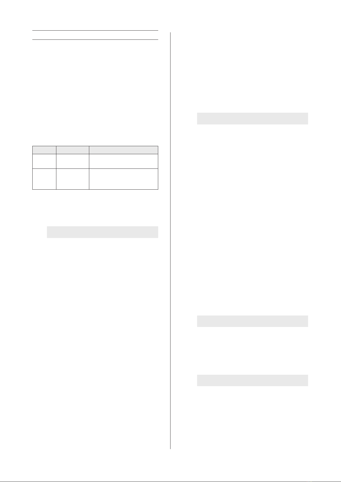
In dieser Montageanleitung werden einige Symbole ver-
wendet. Nachfolgend nden Sie eine Erklärung dieser
Symbole.
Symbol Bedeutung Aktion
Anzeige Erläuterung einer Anzeige auf
der Dunstabzugshaube.
Warnhinweis Dieses Symbol weist auf
einen wichtigen Tipp oder
eine gefährliche Situation hin.
Beachten Sie diese Anleitung, um Verletzungen und Sach-
schäden zu vermeiden.
Warnhinweise vor der Montage
−
Dieses Gerät erfüllt die geltenden Sicherheitsvorschriften.
Eine unsachgemäße Montage kann jedoch zu Verlet-
zungen und Schäden am Gerät führen.
− Das Gerät ist nur für den Hausgebrauch (Zubereitung
von Lebensmitteln) bestimmt, unter Ausschluss aller
anderen haushaltlichen, gewerblichen und industriellen
Zwecke. Das Gerät darf nicht im Freien verwendet
werden.
−
Überprüfen Sie den Zustand des Geräts und des
Montagematerials, sobald Sie es aus der Verpackung
nehmen. Nehmen Sie das Gerät sorgfältig aus der Ver-
packung. Verwenden Sie zum Öffnen der Verpackung
keine scharfen Messer.
−
Installieren Sie das Gerät nicht, wenn es beschädigt ist,
und wenden Sie sich in diesem Fall an Novy.
−
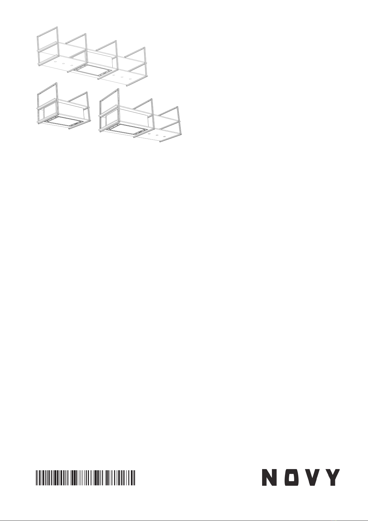
Überprüfen Sie anhand der Zeichnung A , ob alle Mon-
tagematerialien vorhanden sind. Die Fettlter benden
sich in dem Gerät.
−
Novy haftet nicht für Schäden, die durch falsche Mon-
tage, falschen Anschluss, unsachgemäße Verwendung
oder falsche Bedienung entstehen.
− Die Installation und der elektrische Anschluss des Ge-
räts müssen von einem anerkannten Fachmann über-
nommen werden.
−
Die Sicherheit ist nur bei fachgerechter Installation ge-
mäß der Montageanleitung gewährleistet. Derjenige,
der das Gerät installiert, ist für den ordnungsgemäßen
Betrieb am Installationsort verantwortlich.
−
Zur einfacheren Montage des Gerätes wird empfohlen,
diese mit mindestens zwei Personen durchzuführen.
−
Lesen Sie die Gebrauchsanweisung und Montageanlei-
tung sorgfältig durch, bevor Sie dieses Gerät installieren
und in Betrieb nehmen. Darin sind wichtige Informa-
tionen in Bezug auf die Installation und Verwendung
des Geräts enthalten.
−
Metallteile können scharfe Kanten haben, an denen
Sie sich verletzen können. Tragen Sie bei der Montage
Handschuhe, die Sie vor Verletzungen schützen.
Montagevorschriften des Geräts
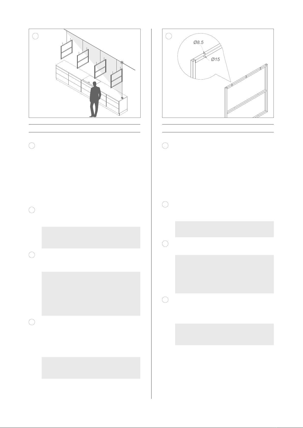
− Stellen Sie sicher, dass die Konstruktion, auf der das
Gerät montiert wird, eine ausreichende Tragfähigkeit
besitzt.
−
Für die ordnungsgemäße Montage, ein ausreichend
stabiles, an die baulichen Gegebenheiten und das Ge-
rätegewicht angepasstes Material verwenden.
−
Das Gerät darf nicht direkt in die Gipskartonplatten oder
ähnliche Leichtbaustoffe montiert werden.
− Defekte oder beschädigte Teile dürfen nur durch Ori-
ginalteile von Novy ersetzt werden.
−
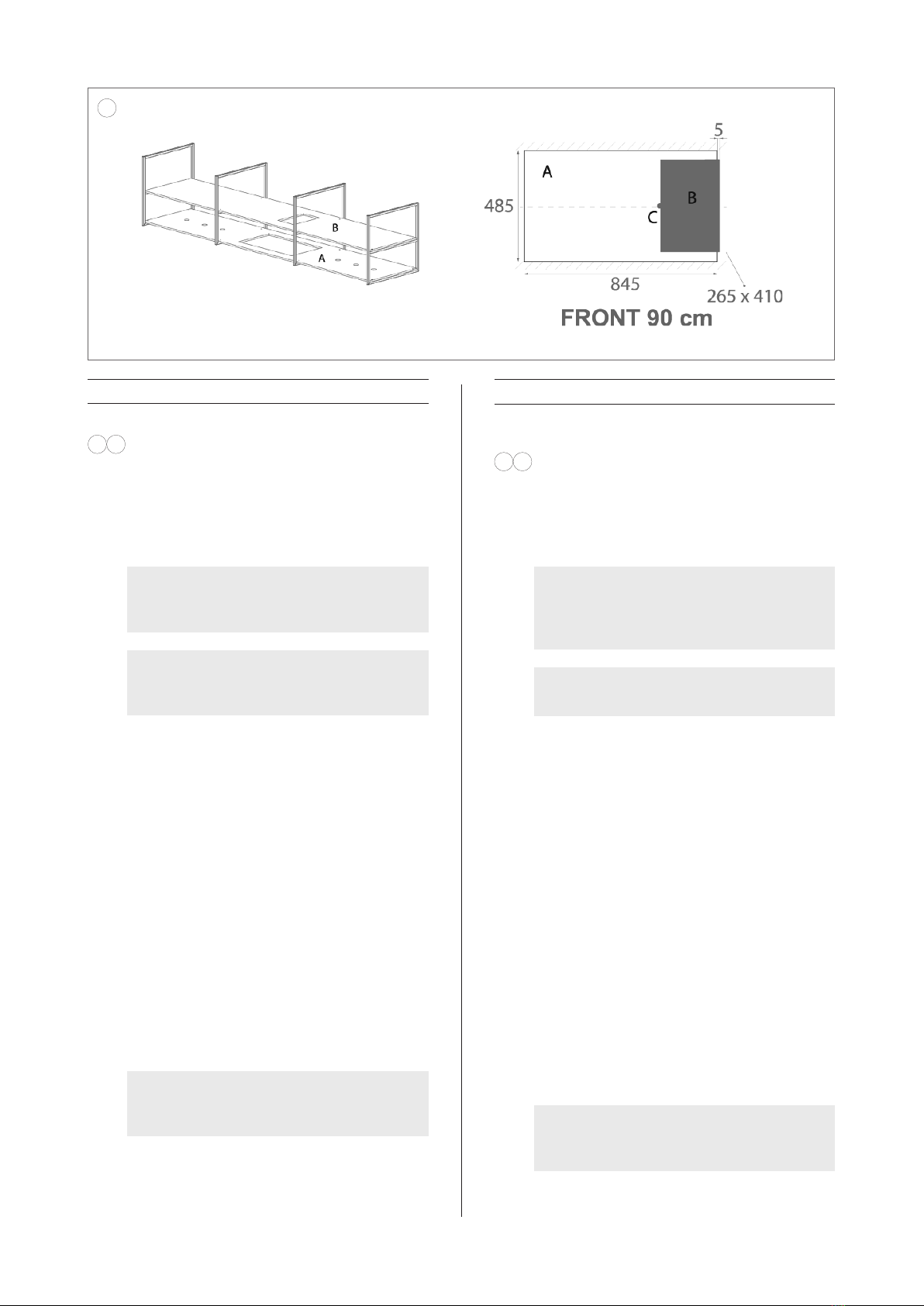
Je größer der Abstand zwischen Gerät und Koch-
feld, desto weniger Kochdämpfe werden vom Gerät
aufgenommen. Beachten Sie daher die angegebene
(empfohlene) Montagehöhe.
−
Wenn in der Installationsanleitung für das Gaskochfeld
ein anderer Abstand angegeben ist, gilt der größte an-
gegebene Abstand.
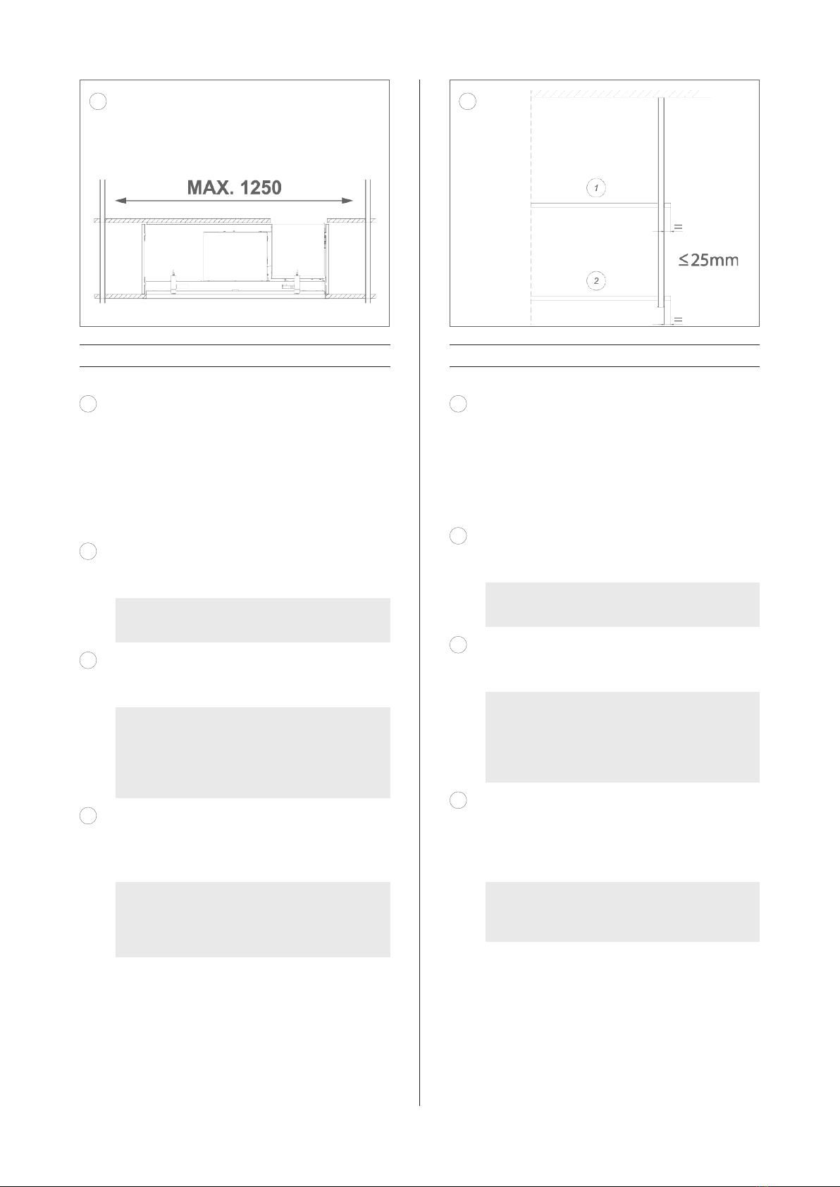
− Um eine optimale Absorption der Kochdämpfe zu ge-
währleisten, muss das Gerät oder die Konstruktion, in
die das Gerät eingebaut wurde, das Kochfeld abdecken.
Stellen Sie bei einer selbst hergestellten Konstruktion
sicher, dass das Gerät mittig über dem Kochfeld mon-
tiert wird.
−
Für eine optimale Leistung darf das Kochfeld nicht größer
sein als das Gerät oder die Konstruktion, in der das
Gerät installiert ist.
Umluft
Die Dunstabzugshaube kann nur als Umluft-Dunstab-
zugshaube verwendet werden.
Die Kochdämpfe werden durch die Fettlter und einen
Geruchslter gereinigt und in die Küche zurückgeführt.
Luftzufuhr
Bei einem Gerät mit Rezirkulation muss in dem Raum, in
dem das Gerät installiert / aufgestellt wurde, eine Min-
destbelüftung gegeben sein. Die Belüftung kann über die
allgemeine Belüftung oder ein geöffnetes Fenster oder
eine geöffnete Tür erfolgen.

7
Elektrischer Anschluss
− Das Gerät darf nur mit einem Netzstecker an eine ge-
erdete Steckdose angeschlossen werden (230V - 50Hz).
−
Wenn der Anschluss mit einem Hauptstecker nicht
möglich ist, muss ein allpoliger Trennschalter gemäß
den Bedingungen der Überspannungskategorie III und
gemäß den Installationsvorschriften in die feste elek-
trische Installation integriert werden. Nur ein zugelasse-
ner Fachmann darf Geräte ohne Stecker anschließen.
−
Die Sicherheit ist nur dann gewährleistet, wenn das Gerät
vorschriftsmäßig an einen Schutzleiter angeschlossen ist.
−
Das Gerät muss jederzeit vom Stromnetz getrennt
werden können.
−
Verwenden Sie kein Verlängerungskabel für den An-
schluss an das Stromnetz.
−
Elektrischer Schlag: Schalten Sie niemals ein defektes
Gerät ein, da dies einen elektrischen Schlag verursachen
kann. Ziehen Sie den Netzstecker aus der Steckdose
oder schalten Sie ihn am Gruppenschrank aus. Wenden
Sie sich an den Kundendienst von Novy.
−
Der Austausch defekter oder beschädigter Kabel sowie
Reparaturen dürfen nur durch von Novy angewiesene
Techniker vorgenommen werden.
−
In das Gerät eingedrungene Feuchtigkeit kann einen
elektrischen Schlag verursachen. Verwenden Sie keinen
Hochdruck- bzw. Dampfreiniger.
2 ZUBEHÖR
InTouch
InTouch bietet die Möglichkeit, die Novy-Dunstabzugs-
haube von der Novy InTouch Induktionskochplatte aus
zu bedienen.
Die Deckeneinheit kann standardmäßig mit allen Novy
InTouch Induktionskochfeldern kombiniert werden.
Auf der Website nden Sie verschiedene Induktionskoch
-
platten-Modelle mit InTouch.
Weitere Informationen zu den Produkten, dem Zubehör
und den Dienstleistungen von Novy nden Sie im Internet
unter: www.novy.com.
EN
1 SAFETY AND ASSEMBLY
REGULATIONS
Further information on Novy products, accessories and
services may be found on the internet: www.novy.com.
These are the installation instructions for the appliance
as shown on the front. The directions for use are in a
separate booklet supplied with the appliance.
These installation instructions make use of a number of
symbols. The meanings of the symbols are shown below.
Symbol Meaning Action
Indication Explanation of an
indication on the hood.
Warning This symbol indicates
an important tip or a
dangerous situation
Observe this instruction in order to prevent injury and
damage to property.
Warnings before installation
−
This appliance complies with the applicable safety
instructions. However, inexpert installation may cause
personal injury or damage to the appliance.
−
The appliance is intended exclusively for household
use (preparation of food) and excludes all other do-
mestic, commercial or industrial use. Do not use the
appliance outside.
−
Check the condition of the appliance and the installation
ttings as soon as you remove them from the packag-
ing. Remove the appliance from the packaging with
care. Do not use sharp knives to open the packaging.
−
Do not install the appliance if it is damaged, and in
that case inform Novy.
− Check on the basis of the drawing A that all the ma-
terials for installation have been supplied. The grease
lters are in the appliance.
− Novy is not liable for damage resulting from incorrect
assembly, incorrect connection, incorrect use or in-
correct operation.
−
The installation and electrical connection of the appli-
ance should be left to a recognised expert.
−
Safety is guaranteed only with expert installation in
accordance with the installation manual. The installing
technician is responsible for proper operation at the
installation location.
− For easier installation of the appliance, it is advisable
to carry it out with at least 2 people.
−
Read the directions for use and the installation instruc-
tions before installing and using this appliance. You
will nd important information here for the assembly
and use of the appliance.
− Metal parts may have sharp edges, and you may in-
jure yourself on them. For that reason, wear protective
gloves during installation.

8
−
Electric shock: never switch on a faulty appliance, this
could cause an electric shock. Take the power plug out
of the socket, or switch off at the distribution cabinet.
Contact the Novy service department.
− Repairs and replacing faulty or damaged wiring must
only be carried out by technicians who have undergone
instruction by Novy.
−
Moisture that has got into the appliance may cause an
electric shock. Do not use a high pressure or steam
cleaner.
2 ACCESSORIES
InTouch
InTouch offers you the possibility to control the Novy
cooker hood from the Novy InTouch induction cooking
plate. The ceiling hood may, as a default, be combined
with InTouch induction cooking plates.
Visit the website for the different models of induction
cooking plates with InTouch.
Further information on Novy products, accessories and
services may be found on the internet: www.novy.com.
Installation instructions for the appliance
− Ensure that the structure on or in which the appliance
is to be installed can bear its weight.
−
To ensure correct installation, you must use a material
which is sufciently stable and suitable for both the
structural conditions and the weight of the appliance.
−
The appliance must not be tted directly onto plaster-
board or similar lightweight materials.
−
Faulty or damaged parts may only be replaced by
original Novy parts.
−
The larger the distance between the appliance and the
hob, the less easily the cooking vapours can be taken
up by the appliance. For this reason, pay heed to the
stated (recommended) installation height.
−
If a different distance is specied in the installation
instructions for the gas hob, the largest distance in-
dicated applies.
− In order to ensure that the cooking vapours are taken
up in an optimal way, the appliance, or the structure into
which the appliance is being installed, should extend
over the hob. When using your own structure, ensure
that the appliance is installed centred above the hob.
−
For optimal operation, the hob should not be larger
than the appliance or the structure into which the ap-
pliance is installed.
Recirculation
The cooker hood can only be used as a recirculation
cooker hood.
The cooking vapours are cleaned by the grease lters
and an odour lter and returned to the kitchen.
Air supply
With an appliance with recirculation, there must be a
minimum of ventilation in the room where the appliance
has been installed / is positioned. Ventilation can be
provided by the overall ventilation in the home or by
tilting a window or opening a door.
Installation instructions for the outlet
−
The appliance may only be connected with the power
plug to a socket with an earth (230 V – 50 Hz).
−
If connection with a main plug is not possible, an all-pole
isolating switch must be integrated into the permanent
electrical installation according to the conditions of
overvoltage category III and according to the installation
regulations. Only a licensed professional may connect
appliances without plugs.
−
Safety is only assured when the appliance is connected
to an earth cable in accordance with the instructions
laid down.
− The appliance must be able to be disconnected from
the power at any desired point.
− Do not use an extension cable for the connection to
the electrical mains.

9
NL
Type
Aantal frames
Breedte
afzuigkap (cm)
Hoogte frame
(cm)
Aantal inbouw-
spots
15001.017
Gewicht* (kg)
15001
2 90 70 0 50
15002
2 120 70 0 55
15003
3 90 70 3 55
15004
3 120 70 3 60
15005
4 90 70 6 60
15006
4 120 70 6 66
15007
2 90 80 0 50
15008
2 120 80 0 56
15009
3 90 80 3 56
15010
3 120 80 3 61
15011
4 90 80 6 61
15012
4 120 80 6 67
* exclusief legplanken, exclusief mogelijke belasting
op deze legplanken
FR
Type
Nombre de
cadres
Largeur de la
hotte (cm)
Hauteur du
cadre (cm)
Nombre de
spots encastrés
Poids* (kg)
15001
2 90 70 0 50
15002
2 120 70 0 55
15003
3 90 70 3 55
15004
3 120 70 3 60
15005
4 90 70 6 60
15006
4 120 70 6 66
15007
2 90 80 0 50
15008
2 120 80 0 56
15009
3 90 80 3 56
15010
3 120 80 3 61
15011
4 90 80 6 61
15012
4 120 80 6 67
* excepté étagères, et excepté charges éventuelles
sur ces étagères
DU
Typ
Anzahl
an Rahmen
Breite Dunstab-
zugshaube (cm)
Höhe Rahmen
(cm)
Anzahl
Einbaustrahler
15001.017
Gewicht* (kg)
15001
2 90 70 0 50
15002
2 120 70 0 55
15003
3 90 70 3 55
15004
3 120 70 3 60
15005
4 90 70 6 60
15006
4 120 70 6 66
15007
2 90 80 0 50
15008
2 120 80 0 56
15009
3 90 80 3 56
15010
3 120 80 3 61
15011
4 90 80 6 61
15012
4 120 80 6 67
* ohne Regale, ohne mögliche Belastung dieser
Regalböden
EN
Type
Number of
frames
Width cooker
hood (cm)
Height frame
(cm)
Number of
recessed spot-
lights 15001.017
Weight* (kg)
15001
2 90 70 0 50
15002
2 120 70 0 55
15003
3 90 70 3 55
15004
3 120 70 3 60
15005
4 90 70 6 60
15006
4 120 70 6 66
15007
2 90 80 0 50
15008
2 120 80 0 56
15009
3 90 80 3 56
15010
3 120 80 3 61
15011
4 90 80 6 61
15012
4 120 80 6 67
* excluding shelves, excluding possible load on these
shelves

10
FR
La hauteur de montage recommandée pour une
plaque de cuisson électrique ou céramique est de 600 mm
au minimum et de 850 mm au maximum. La hauteur de
montage pour une plaque de cuisson au gaz ou à induc-
tion est de 650 mm au minimum et de 850 mm au maxi-
mum.
En raison du poids total considérable de la construc-
tion complète, incluant les matériaux choisis pour les
étagères et les éventuelles charges sur celles-ci, le pla-
fond doit offrir une capacité portante suffisante. En cas de
doute, demandez l’avis d’un entrepreneur ou d’un archi-
tecte. Ils pourront vérifier directement sur place la struc-
ture du plafond et le poids qu’il peut supporter ou non.
N’installez pas directement dans des plaques de
plâtre ou d’autres matériaux de construction légers simi-
laires. Choisissez du matériel de montage (chevilles et vis)
adapté à la situation et au poids total de la construction,
incluant les matériaux choisis pour les étagères et les
éventuelles charges sur celles-ci.
Avec des cadres fixes, il n’est pas possible de s’ajus-
ter aux imperfections du plafond, c’est pourquoi Novy
recommande de prêter une attention particulière à la
planéité de la surface du plafond.
Étagères (autonomes)
Épaisseur 18 à 25 mm
Largeur 750 mm
La longueur des étagères dépend de la construction
choisie. L’étagère doit offrir une capacité portante et une
stabilité suffisantes pour supporter le poids de la hotte et
des éventuelles charges posées sur ladite étagère.
Raccordement électrique
Attention, ne procédez pas à l’installation sous tension.
Assurez-vous que le circuit électrique auquel l’appareil est
connecté est hors tension.
NL
De adviesmontagehoogte met een elektrische of
keramische kookplaat is minimaal 600 mm en maximaal
850 mm. De montagehoogte met een gas of inductiekook-
plaat is minimaal 650 mm en maximaal 850 mm.
Door het aanzienlijke totale gewicht van de com-
plete constructie inclusief het gekozen materiaal van de
legplanken en mogelijke belasting op deze legplanken
dient het plafond voldoende draagkracht te hebben. Laat
bij twijfel een aannemer of architect de situatie beoor-
delen. Zij kunnen ter plaatste bekijken hoe het plafond is
opgebouwd en welk gewicht het plafond al dan niet kan
dragen.
Niet rechtstreeks monteren in gipsplaten of ge-
lijksoortig licht bouwmateriaal. Kies montagemateriaal
(pluggen en schroeven) welke geschikt is voor de bouw-
kundige situatie en het totale gewicht van de complete
constructie inclusief het gekozen materiaal van de leg-
planken en mogelijke belasting op deze legplanken.
Daar er gewerkt wordt met vaste frames zijn onvol-
komenheden in het plafond niet in het frame bij te sturen,
derhalve adviseert Novy om extra aandacht te besteden
aan de vlakheid van het plafondoppervlak.
Legplanken (zelf voorzien)
Dikte 18 - 25mm
Breedte 750 mm
De lengte van de legplanken wordt bepaald door de geko-
zen constructie. De legplank moet voldoende draagkracht
en stabiliteit hebben voor het gewicht van de afzuigkap en
mogelijke belasting op deze legplanken.
Elektrische aansluiting
Let op, niet onder spanning monteren.
Zorg dat het stroomcircuit waar het apparaat op wordt
aangesloten, is uitgeschakeld.

11
DU
Die empfohlene Montagehöhe für ein Elektro- oder
Keramikkochfeld beträgt mindestens 600 mm und höchs-
tens 850 mm. Die Montagehöhe für ein Gas- oder Induk-
tionskochfeld beträgt mindestens 650 mm und maximal
850 mm.
Aufgrund des beträchtlichen Gesamtgewichts der
gesamten Konstruktion, einschließlich des gewählten
Regalmaterials und möglicher Lasten auf diesen Regal-
böden, muss die Decke eine ausreichende Tragfähigkeit
aufweisen. Im Zweifelsfall sollten Sie die Situation von
einem Bauunternehmer oder Architekten prüfen lassen.
Sie können vor Ort prüfen, wie die Decke aufgebaut ist
und welches Gewicht die Decke tragen kann oder nicht.
Montieren Sie nicht direkt in Gipskartonplatten oder
ähnlichen Leichtbaumaterialien. Wählen Sie Befestigungs-
material (Dübel und Schrauben), das für die baulichen
Gegebenheiten und das Gesamtgewicht der gesamten
Konstruktion geeignet ist, einschließlich des gewählten
Regalmaterials und möglicher Belastung dieser Regal-
böden.
Da feste Rahmen verwendet werden, können Un-
ebenheiten in der Decke nicht durch den Rahmen ausge-
glichen werden, weshalb Novy empfiehlt, besonders auf
die Ebenheit der Deckenfläche zu achten.
Regalböden (selbsttragend)
Dicke 18 - 25 mm
Breite 750 mm
Die Länge der Regalböden wird durch die gewählte
Konstruktion bestimmt. Der Regalboden muss eine aus-
reichende Tragfähigkeit und Stabilität für das Gewicht der
Dunstabzugshaube und mögliche Belastungen auf diesen
Regalböden aufweisen.
Elektrischer Anschluss
Vorsicht: Vor dem Installieren spannungslos machen.
Stellen Sie sicher, dass der Stromkreis, an den das Gerät
angeschlossen wird, ausgeschaltet ist.
EN
The recommended mounting height for an electric or
ceramic hob is minimum 600 mm and maximum 850 mm.
The mounting height for a gas or induction hob is mini-
mum 650 mm and maximum 850 mm.
Due to the considerable total weight of the entire
construction, including the chosen shelf material and pos-
sible loads on these shelves, the ceiling must have suffi-
cient load-bearing capacity. If in doubt, have a contractor
or architect check the situation. They can check on site
how the ceiling is constructed and what weight the ceiling
can or cannot support.
Do not install directly into plasterboard or similar
lightweight construction materials.
Select mounting material (dowels and screws) that is
suitable for the construction situation and the total weight
of the entire construction, including the selected shelf
material and possible loads on these shelves.
As fixed frames are used, imperfections in the ceil-
ing cannot be adjusted in the frame, which is why Novy
recommends paying extra attention to the flatness of the
ceiling surface.
Shelves (self-sufficient)
Thickness 18 - 25 mm
Width 750 mm
The length of the shelves is determined by the chosen
construction. The shelf must have sufficient bearing cap-
acity and stability for the weight of the cooker hood and
possible loads on these shelves.
Electrical connection
Caution, do not install under voltage.
Ensure that the power circuit to which the device is con-
nected is switched off.

12
43
5
2x 15001.002 90cm
/
2x 15001.003 120cm
2x 15001.001
1x 15001.011 1x 15001.010 1x 7300.556
2/3/4x 15001.004 70cm
/
2/3/4x 15001.005 80cm
2x 15001.002 90cm
/
2x 15001.003 120cm
2x 15001.001
1x 15001.011 1x 15001.010 1x 7300.556
2/3/4x 15001.004 70cm
/
2/3/4x 15001.005 80cm
2x 15001.002 90cm
/
2x 15001.003 120cm
2x 15001.001
1x 15001.011 1x 15001.010 1x 7300.556
2/3/4x 15001.004 70cm
/
2/3/4x 15001.005 80cm
2x 15001.002 90cm
/
2x 15001.003 120cm
2x 15001.001
1x 15001.011 1x 15001.010 1x 7300.556
2/3/4x 15001.004 70cm
/
2/3/4x 15001.005 80cm
40x 906.690
(3.5x16 black)
4x 906.691
0/1/2x
15001.015
0/1/2x 15001.014 0/1/2x 15001.013
0/3/6x 15001.017 2x 15001.039 1x 15001.012
40x 906.690
(3.5x16 black)
4x 906.691
0/1/2x
15001.015
0/1/2x 15001.014 0/1/2x 15001.013
0/3/6x 15001.017 2x 15001.039 1x 15001.012
1x 7530.070
1x 840.049
1x 1010.262
2 x 75300.84 2 x 7530.085 1x 10237 1x 661057
1x 7530.087
12x 906.689 4x 906.116 36x 906.687
(4.0x16)
16x 15001.035 8x 15001.006
8x 7903.084
1x 7530.070
1x 840.049
1x 1010.262
2 x 75300.84 2 x 7530.085 1x 10237 1x 661057
1x 7530.087
12x 906.689 4x 906.116 36x 906.687
(4.0x16)
16x 15001.035 8x 15001.006
8x 7903.084
1x 7530.070
1x 840.049
1x 1010.262
2 x 75300.84 2 x 7530.085 1x 10237 1x 661057
1x 7530.087
12x 906.689 4x 906.116 36x 906.687
(4.0x16)
16x 15001.035 8x 15001.006
8x 7903.084

13
NL 3 INSTALLATIE
1
Let op, niet onder spanning monteren.
Zorg ervoor dat het stroomcircuit
waar het apparaat op aangesloten
wordt, is uitgeschakeld.
2
Verwijder het deksel van de verpakking. Leg al
het materiaal terzijde; in volgende stappen heeft
u deze nodig.
DU 3 INSTALLATION
1
Vorsicht: Vor dem Installieren
spannungslos machen. Stellen Sie
sicher, dass der Stromkreis, an
den das Gerät angeschlossen wird,
ausgeschaltet ist.
2Entnehmen Sie den Deckel aus der Verpackung.
Legen Sie das gesamte Material beiseite; Sie
benötigen es in den nächsten Schritten.
FR 3 INSTALLATION
1
Attention, ne procédez pas à
l'installation sous tension. Assurez-
vous que le circuit électrique auquel
l'appareil est connecté est hors
tension.
2Sortez le couvercle de l’emballage. Gardez tout
le matériel sur le côté, vous en aurez besoin aux
prochaines étapes.
EN 3 INSTALLATION
1
Caution, do not install under voltage.
Ensure that the power circuit to which
the device is connected is switched
off.
2Remove the lid from the packaging. Set aside all
the material; you will need this in the next steps.
1

14
NL
Montage frames
3
Bepaal de breedte van de totale constructie en
de plaats van de frames binnen deze constructie.
Maximale afstand tussen twee frames is
1.250 mm.
Minimale afstand tussen 2 frames voor de afzuigkap
van 90cm inclusief afzuigkapbehuizing: 940 mm
Minimale afstand tussen 2 frames voor de
afzuigkap van 120cm inclusief afzuigkapbehuizing:
1.240 mm
4
Het advies is om de kopse zijden van de legplanken
maximaal 25 mm buiten de eerste en laatste frames
te laten uitsteken.
Let erop dat de afzuigkap gecentreerd bo-
ven de kookplaat gemonteerd moet worden.
5Teken de boorgaten (3 stuks per frame) af op het
plafond en zorg dat de frames onderling uitgelijnd
zijn.
Kies montagemateriaal (pluggen en schroe-
ven) welke geschikt zijn voor de bouwkun-
dige situatie en het totale gewicht van de
complete constructie inclusief legplanken
en mogelijke belasting op deze legplanken.
6De maximale diameter schroef frame: 8 mm
De maximale diameter passeergat frame: 15 mm
Boor de afgetekende boorgaten met een geschikte
boor.
Hou rekening met de grootte van de ruimte
versus de lengte van de legplanken tij-
dens het monteren van de frames aan het
plafond.
FR
Montage des cadres
3
Déterminez la largeur de la structure complète et
l’emplacement des cadres dans cette structure.
La distance maximum entre deux cadres est de
1 250 mm.
La distance minimum entre deux cadres pour
hotte de 90 cm avec boîtier : 940 mm
La distance minimum entre deux cadres pour
hotte de 120 cm avec boîtier : 1 240 mm
4
Nous recommandons que les extrémités des
étagères chevauchent le premier et le dernier
cadre sur 25 mm maximum.
La hotte doit être centrée au-dessus de la
plaque de cuisson.
5Marquez les trous de perçage (3 par cadre) sur
le plafond et assurez-vous que les cadres sont
mutuellement alignés.
Choisissez du matériel de montage (che-
villes et vis) adapté à la situation et au
poids total de la construction, incluant les
matériaux choisis pour les étagères et les
éventuelles charges sur celles-ci.
6Diamètre maximum de vis pour cadre : 8 mm
Diamètre maximum d’ouverture dans cadre :
15 mm
Percez les trous marqués à la mèche avec une
mèche adaptée.
Tenez compte de la taille de la pièce par
rapport à la longueur des étagères lorsque
vous fixez les cadres au plafond.
34

15
DU
Montage der Rahmen
3
Bestimmen Sie die Breite der Gesamtstruktur
und die Position der Rahmen innerhalb dieser
Struktur.
Der maximale Abstand zwischen zwei Rahmen
beträgt 1.250 mm.
Mindestabstand zwischen zwei Rahmen für
90 cm Dunstabzugshaube einschließlich
Dunstabzugshaubengehäuse: 940 mm
Mindestabstand zwischen zwei Rahmen für
120 cm Dunstabzugshaube einschließlich
Dunstabzugshaubengehäuse: 1.240 mm
4Wir empfehlen, dass die Enden der Regalböden
den ersten und letzten Rahmen um maximal 25
mm überlappen.
Beachten Sie, dass die Dunstabzugshaube
genau mittig über dem Kochfeld ange-
bracht werden muss.
5Markieren Sie die Bohrlöcher (drei pro Rahmen)
an der Decke und achten Sie darauf, dass die
Rahmen zueinander ausgerichtet sind.
Wählen Sie Befestigungsmaterial (Dübel
und Schrauben), das für die baulichen Ge-
gebenheiten und das Gesamtgewicht der
gesamten Konstruktion geeignet ist, ein-
schließlich des gewählten Regalmaterials
und möglicher Belastung dieser Regalbö-
den.
6
Maximaler Durchmesser des Schraubrahmens:
8 mm.
Maximaler Durchmesser des Durchgangsrahmens:
15 mm.
Bohren Sie die markierten Bohrlöcher mit einem
geeigneten Bohrer.
Berücksichtigen Sie bei der Montage der
Rahmen an der Decke die Größe des Rau-
mes und die Länge der Regalböden.
EN
Montage frames
3
Determine the width of the total structure and the
location of the frames within this structure.
Maximum distance between two frames is
1,250 mm.
Minimum distance between 2 frames for 90 cm
cooker hood including cooker hood casing :
940 mm
Minimum distance between 2 frames for 120
cm cooker hood including cooker hood casing :
1,240 mm
4
We recommend that the ends of the shelves
overlap the rst and last frames by a maximum
of 25 mm.
Please note that the cooker hood must be
mounted centrally above the hob.
5
Mark the drill holes (3 per frame) on the ceiling
and make sure the frames are mutually aligned.
Select mounting material (dowels and
screws) that is suitable for the construc-
tion situation and the total weight of the
entire construction, including the selected
shelf material and possible loads on these
shelves.
6The maximum diameter screw frame : 8mm
The maximum diameter pass-throug opening
frame : 15mm
Drill the marked drill holes with a suitable drill.
Take the size of the room versus the length
of the shelves into account when mounting
the frames to the ceiling.
5 6
Ø8.5
Ø15

16
NL
Uitsparing legplanken voor afzuigkap en recirculatiebox
7a 7b
Maak gebruik van de lijntekeningen in de handleiding
als de uitsparingen voor afzuigkap en recirculatiebox
ter plaatse gemaakt moeten worden.
Voor de montage van de afzuigkap dient er een
uitsparing gemaakt te worden in de onderste
legplank. Bepaal de plaats en teken de uitsparing
af met behulp van de lijntekening.
Gebruik de juiste lijntekening afhankelijk
van breedte/type afzuigkap. Hou rekening
met de afmeting van de afzuigkapbehuizing
Let erop dat de afzuigkap gecentreerd
boven de kookplaat gemonteerd moet
worden.
Maak de uitsparing voor de afzuigkap in de
onderste legplank.
Type met afzuigkap 90 cm - Uitsparing 845 mm
x 485 mm
Type met afzuigkap 120 cm– Uitsparing 1145 mm
x 485 mm
De afzuigkap dient gemonteerd te worden met de
bediening aan de rechterzijde van de gebruiker,
zodat de onderplaat van u weg scharniert en de
vetlter eenvoudig uit de afzuigkap genomen kan
worden. In deze positie staat de recirculatiebox
aan de rechterzijde op de afzuigkap.
In de bovenste legplank een uitsparing maken voor
het uitblaasrooster van de recirculatiebox en een
passeergat voor de elektrische aansluiting naar
het plafond. Teken de uitsparing en passeergat
af met behulp van de lijntekening.
Maak de uitsparing voor het uitblaasrooster in de
bovenste legplank: Uitsparing 265mm x 410mm.
Hou rekening met de onderlinge positie van
de uitsparing voor de recirculatiebox en
uitsparing voor de afzuigkap.
Het is aan te bevelen beide uitsparingen waterdicht
af te werken.
FR
Étagères à ouverture découpée pour la hotte et le
caisson de recirculation
7a 7b
Référez-vous au dessin du manuel si les découpes
de la hotte et du caisson de recirculation doivent
être réalisées sur place.
Pour monter la hotte, une découpe doit être faite
dans l’étagère du bas. Déterminez la position et
marquez l’ouverture à découper d’après le dessin.
Référez-vous au dessin approprié en fonc-
tion de la largeur/du type de la hotte. Tenez
compte des dimensions du boîtier de la
hotte.
La hotte doit être centrée au-dessus de la
plaque de cuisson.
Réalisez la découpe pour la hotte dans l’étagère
du bas.
Type avec hotte de 90 cm - Découpe de 845 mm
x 485 mm
Type avec hotte de 120 cm - Découpe de
1145 mm x 485 mm
La hotte doit être montée avec les commandes
placées sur la droite de l’utilisateur, de sorte que
le panneau inférieur s’ouvre loin de vous et que
le ltre à graisse puisse être facilement retiré
de la hotte. Dans cette position, le caisson de
recirculation est à la droite de la hotte.
Réalisez une découpe dans l’étagère du haut pour
la grille de sortie du caisson de recirculation et une
ouverture d’entrée de câbles pour le raccordement
électrique au plafond. Utilisez le dessin pour
marquer la découpe et l’ouverture d’entrée de
câbles.
Réalisez la découpe pour la grille de sortie du
caisson de recirculation : découpe de 265 mm x
410 mm.
Respectez la position respective de la dé-
coupe du caisson de recirculation et de la
découpe de la hotte.
Il est recommandé de réaliser une nition étanche
des ouvertures de la découpe.
7a

17
DU
Ausschnitt für Dunstabzugshaube und Umluftkasten
7a 7b
Fertigen Sie anhand der Zeichnung im Handbuch
die Ausschnitte für die Dunstabzugshaube und den
Umluftkasten an, sofern dies vor Ort geschieht.
Um die Dunstabzugshaube zu montieren, muss
ein Ausschnitt im unteren Regalboden angebracht
werden. Bestimmen Sie die Position und markieren
Sie die Ausschnittöffnung anhand der Zeichnung.
Verwenden Sie je nach Breite/Typ der Dunst-
abzugshaube die entsprechende Zeichnung.
Berücksichtigen Sie dabei die Abmessungen
des Dunstabzugshaubengehäuses.
Beachten Sie, dass die Dunstabzugshaube
genau mittig über dem Kochfeld angebracht
werden muss.
Fertigen Sie den Ausschnitt für die Dunstabzugshaube
im unteren Regalboden an.
Typ mit Dunstabzugshaube 90 cm - Ausschnitt 845
mm x 485 mm
Typ mit Dunstabzugshaube 120 cm - Ausschnitt
1145 mm x 485 mm
Die Dunstabzugshaube muss mit den Steuerungen
auf der rechten Seite des Anwenders montiert
werden, sodass die Grundplatte sich von Ihnen
weg öffnet und der Fettlter problemlos aus der
Dunstabzugshaube entfernt werden kann. In dieser
Position bendet sich der Umluftkasten auf der
rechten Seite der Dunstabzugshaube.
Schneiden Sie in den oberen Regalboden einen
Ausschnitt für das Auslassgitter des Umluftkastens
und eine Kabeleinführungsöffnung für den elektrischen
Anschluss an der Decke aus. Markieren Sie den
Ausschnitt und die Kabeleinführungsöffnung anhand
der Zeichnung.
Fertigen Sie den Ausschnitt für das Abluftgitter des
Umluftkastens an: Ausschnitt 265 mm x 410 mm.
Beachten Sie die Lage des Ausschnitts für
den Umluftkasten zum Ausschnitt für die
Dunstabzugshaube.
Es wird empfohlen, die Öffnungen der Ausschnitte
wasserdicht abzuschließen.
EN
Cut-out opening shelves for cooker hood and recir-
culation box
7a 7b Use the drawing in the manual if the cut-outs for
the cooker hood and recirculation box are to be
made on site.
To mount the cooker hood, a cut-out must be
made in the lower shelf. Determine the position
and mark the cut-out opening using the drawing.
Use the appropriate drawing depending on
the width/type of the cooker hood. Take the
dimensions of the cooker hood casing into
account.
Please note that the cooker hood must be
mounted centrally above the hob.
Make the cut-out for the cooker hood in the lower
shelf.
Type with cooker hood 90 cm - Cut-out 845 mm
x 485 mm
Type with cooker hood 120 cm - Cut-out
1145 mm x 485 mm
The cooker hood must be mounted with the
controls on the right-hand side of the user, so
that the bottom panel opens away from you and
the grease lter can be easily removed from the
cooker hood. In this position, the recirculation
box is on the right side of the cooker hood.
Make a cut-out in the upper shelf for the recirculation
box's outlet grille and a cable entry opening for
the electrical connection to the ceiling. Use the
drawing to mark the cut-out and the cable entry
opening.
Make the cut-out for the recirculation box's outlet
grille: cut-out 265 mm x 410 mm.
Observe the mutual position of the recir-
culation box cut-out and the cooker hood
cut-out.
It is recommended to nish the cut-out openings
watertight.
7b

18
8
9

19
NL
Plaatsen legplanken
8Plaats de legplanken op de frames. Plaats eerst
de bovenste legplank en vervolgens de onderste.
Uitlijnen van de legplanken
9
• Verdeel de lengte van de legplanken over de
frameconstructie en zorg dat beide uiterste
zijden van de legplanken evenveel buiten de
frames vallen.
• Lijn de diepte uit van de legplanken binnen
alle frames (breedte legplank 750 mm versus
binnenzijde frame 756 mm).
• Controleer of de frames haaks aan het plafond
hangen.
• Fixeer met de zelfborende schroeven (15001.035)
de legplanken aan de frames (2 stuks per leg-
plank / per frame). Het wordt aangeraden om
de gaten in de plank voor te boren en de kop
van de schroef te verzinken.
FR
Positionnement des étagères
8
Positionnez les étagères sur les cadres. Placez
d’abord l’étagère du haut puis celle du bas.
Alignement des étagères
9
• Divisez la longueur des étagères par la construction
de cadres et assurez-vous que les deux côtés
extérieurs des étagères tombent à l’extérieur
des cadres de manière équivalente.
• Alignez la profondeur des étagères dans tous
les cadres (largeur des étagères de 750 mm par
rapport à l’intérieur du cadre de 756 mm).
• Vériez que les cadres sont montés à un angle
de 90 degrés par rapport au plafond.
• Fixez les étagères aux cadres à l’aide des vis
auto-foreuses (15001.035) (2 par étagère/cadre).
Nous recommandons de préforer les trous dans
l’étagère et de fraiser la tête de la vis.
DU
Positionieren der Regalböden
8
Positionieren Sie die Regalböden auf den Rahmen.
Setzen Sie zuerst den oberen und dann den
unteren Regalboden ein.
Ausrichten der Regalböden
9
• Teilen Sie die Länge der Regalböden auf die
Rahmenkonstruktion auf und achten Sie darauf,
dass die Regalböden außen gleich weit aus den
Rahmen herausragen.
• Richten Sie die Tiefe der Regalböden innerhalb
aller Rahmen aus (Regalbodenbreite 750 mm
vs. Rahmeninnenseite 756 mm).
• Prüfen Sie, ob die Rahmen im 90 Grad-Winkel
zur Decke montiert sind.
• Befestigen Sie die Regalböden mit den selbst-
schneidenden Schrauben (15001.035) an den
Rahmen (zwei pro Boden/Rahmen). Wir emp-
fehlen, die Löcher im Regalboden vorzubohren
und für den Schraubenkopf anzusenken.
EN
Position shelves
8
Position the shelves on the frames. First place
the upper shelf and then the bottom one.
Aligning the shelves
9• Divide the length of the shelves over the frame
construction and make sure that both outer
sides of the shelves fall outside the frames by
the same amount.
• Align the depth of the shelves within all frames
(shelf width 750 mm vs. inside frame 756 mm).
• Check that the frames are mounted at 90 degrees
to the ceiling.
• Fix the shelves to the frames with the self-drill-
ing screws (15001.035) (2 per shelf/frame). We
recommend pre-drilling the holes in the shelf
and countersinking the head of the screw.

20
When using
18-22 mm thick shelves.
10 11
12
This manual suits for next models
11
Table of contents
Other Novy Ventilation Hood manuals
Popular Ventilation Hood manuals by other brands

Kuppersberg
Kuppersberg Slimlux II 50 Technical Passport

Best
Best K3500 Series user guide

CyClone
CyClone BX212 Assembly, installation and operation instructions

Whirlpool
Whirlpool LI3Y5B Installation Instructions and Use & Care Guide

KitchenAid
KitchenAid 30" Freestanding Range Installation Instructions and Use & Care Guide

Exido
Exido exido 258-015 user guide