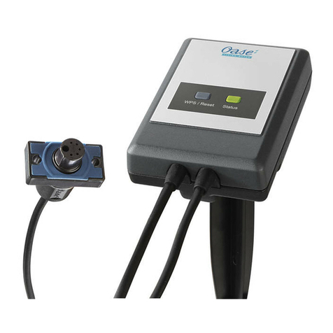
Oase StreamMax Pump Controller User manual

StreamMax Pump Controller

5
2 StreamMax Pump Controller
A
SMX0021
B
SMX0018

5
3
C
SMX0022
D
SMX0007

-DE -
4 StreamMax Pump Controller
-DE -
Original Gebrauchsanleitung
WARNUNG
•Dieses Gerät kann von Kin-
dern ab 8 Jahren und darüber
sowie von Personen mit ver-
ringerten physischen, sensori-
schen oder mentalen Fähig-
keiten oder Mangel an Erfah-
rung und Wissen benutzt
werden, wenn sie beaufsich-
tigt oder bezüglich des siche-
ren Gebrauchs des Gerätes
unterwiesen wurden und die
daraus resultierenden Gefah-
ren verstehen.
•Kinder dürfen nicht mit dem
Gerät spielen.
•Reinigung und Benutzerwar-
tung dürfen nicht von Kindern
ohne Beaufsichtigung durch-
geführt werden.
•Das Gerät muss über eine
Fehlerstrom-
Schutzeinrichtung mit einem
Bemessungsfehlerstrom von
maximal 30 mA abgesichert
sein.
•Alle Geräte im Aquarium aus-
schalten oder den Netzstecker
ziehen, bevor Sie in das Was-
ser greifen.
•Gerät nicht verwenden, wenn
elektrische Leitungen oder
Gehäuse beschädigt sind.
•Eine beschädigte Anschlusslei-
tung kann nicht ersetzt wer-
den. Gerät entsorgen.
•Vor Arbeiten am Gerät Netz-
stecker ziehen.
SICHERHEITSHINWEISE
•Gerät nur anschließen, wenn die elektrischen
Daten von Gerät und Stromversorgung überein-
stimmen. Die Gerätedaten befinden sich auf dem
Typenschild am Gerät, auf der Verpackung oder in
dieser Anleitung.
•Gerät nicht an der elektrischen Leitung tragen oder
ziehen.
•Leitungen geschützt vor Beschädigungen verlegen
und darauf achten, dass niemand darüber fallen
kann.
•Nur die Arbeiten am Gerät durchführen, die in
dieser Anleitung beschrieben sind. Wenn sich Pro-
bleme nicht beheben lassen, eine autorisierte Kun-
dendienststelle oder im Zweifelsfall den Hersteller
kontaktieren.
•Niemals technische Änderungen am Gerät vor-
nehmen.
•Nur Original-Ersatzteile und –Zubehör für das
Gerät verwenden.
•Steckerverbindungen vor Feuchtigkeit schützen.
•Gerät nur an einer vorschriftsmäßig installierten
Steckdose anschließen.
Warnhinweise in dieser Anleitung
Die Warnhinweise in dieser Anleitung sind durch
Signalworte klassifiziert, die das Ausmaß der Gefähr-
dung anzeigen.
WARNUNG
Kennzeichnet eine möglicherweise gefährliche Situa-
tion, die den Tod oder schwere Verletzungen zur
Folge haben kann, wenn sie nicht vermieden wird.
HINWEIS
Kennzeichnet eine möglicherweise gefährliche Situa-
tion, die Sach- oder Umweltschäden zur Folge haben
kann, wenn Sie nicht vermieden wird.
Verweise in dieser Anleitung
5A Verweis auf eine Abbildung, z. B. Abbildung A.
→Verweis auf ein anderes Kapitel.

-DE -
5
PRODUKTBESCHREIBUNG
Am StreamMax Pump Controller können max. zwei
StreamMax Premium Strömungspumpen angeschlos-
sen werden. Das Gerät regelt die Drehzahl der ange-
schlossenen Strömungspumpen. Mittels EAC Aquari-
um Controller kann der StreamMax Pump Controller
in das Easy Aquarium Control-System (EAC) integriert
werden.
Easy Aquarium Control-System (EAC)
Dieses Produkt kann mit dem Easy Aquarium Control-
System (EAC) kommunizieren. EAC bietet komfortable
Steuerungsmöglichkeiten über Smartphone oder
Tablet und gewährleistet hohen Komfort und Sicher-
heit. Informationen zu EAC und den Möglichkeiten
erhalten Sie unter: www.oase-livingwater.com/eac-
start
Geräteaufbau und Lieferumfang
5A
StreamMax Pump Controller
1
StreamMax Pump Controller
2
Netzteil
3
Netzkabel
4
Datenkabel, zum Anschluss des StreamMax Pump
Controller an den EAC Aquarium Controller
Bestimmungsgemäße Verwendung
StreamMax Pump Controller, "Gerät" genannt, darf
ausschließlich wie folgt verwendet werden:
•Zur Steuerung von StreamMax Premium Pumpen.
•Betrieb unter Einhaltung der technischen Daten.
(→ Technische Daten)
•Nur mit originalem Netzteil betreiben.
•Nur in Räumen und für private aquaristische Zwek-
ke verwenden.
Zubehör
•StreamMax Premium Strömungspumpe 2000
(33948) / 4000 (33949) / 5000 (33955).
•EAC Aquarium Controller (33885).
ANSCHLIEßEN
5B, C
•P1/P2: Stecker der Strömungspumpe in die Buchse
am StreamMax Pump Controller stecken.
– Anschlussleitung mit Schlaufe verlegen, damit
herabtropfendes Wasser nicht in die Buchse
eindringen kann.
•Power: Stecker des Netzteils in die Buchse am
StreamMax Pump Controller stecken.
– Kräftig drücken, bis der Stecker einrastet.
•EAC: StreamMax Pump Controller und EAC Aquari-
um Controller mit dem Datenkabel verbinden (op-
tional).
– Rastnase des RJ-45-Steckers muss einrasten.
INBETRIEBNAHME
Die Inbetriebnahme erfolgt in dieser Reihenfolge:
1. StreamMax Pump Controller einschalten. (→ Gerät
ein-/ausschalten)
2. Angeschlossene Strömungspumpen konfigurieren,
damit diese angesteuert werden können.
(→ Anschlüsse P1 und P2 konfigurieren)
3. Strömungspumpen für den Betriebsmodus "Fütte-
rung" konfigurieren. (→ Betriebsmodus "Fütte-
rung" konfigurieren)
4. Gewünschten Modus zur Drehzahlsteuerung
aktivieren. (→ Betriebsmodus und Konfigurations-
modus)
Gerät ein-/ausschalten
•Einschalten: Gerät mit dem Netz verbinden. Das
Gerät schaltet sich sofort ein.
•Ausschalten: Gerät vom Netz trennen.
BEDIENUNG
Anzeige und Tasten
•Die Anzeige blinkt ca. 10 s nach Bestätigung einer
Drehzahl oder eines Strömungsprofils.
•Nach ca. 40 s ohne Bedienung, schaltet die
Anzeige aus.
−Der Punkt signalisiert den Betrieb des Geräts.
−Eine beliebige Taste drücken, um die Anzeige
wieder einzuschalten.
Ebene zurück
Vorwärts blättern, Wert erhöhen
Rückwärts blättern, Wert verringern
•In die Eingabeebene wechseln.
•Auswahl bzw. Wert bestätigen.
−Werte werden direkt übernommen.
•Fütterungsmodus aktivieren: Taste ca. 3 s ge-
drückt halten.

-DE -
6 StreamMax Pump Controller
Betriebsmodus und Konfigurationsmodus
Betriebsmodus
Beide Strömungspumpen ausschalten. Nach dem
Einschalten des Geräts ist automatisch dieser Modus
aktiviert.
Fütterung. Die Drehzahl beider Strömungspumpen
schaltet für 3 Minuten auf 0 oder auf 10 %.
(→ Betriebsmodus "Fütterung" konfigurieren)
Drehzahl in % für die Strömungspumpen an P1 und P2
vorgeben.
0-100
Schrittweite: 10 %.
Drehzahl in % für die Strömungspumpe an P1 vorge-
ben.
0-100
Schrittweite: 10 %.
Drehzahl in % für die Strömungspumpe an P2 vorge-
ben.
0-100
Schrittweite: 10 %.
Vordefiniertes Strömungsprofil vorgeben.
Konfigurationsmodus
StrömungsStrömungspumpe an P1 und P2
festlegen.
Keine Strömungspumpe
StreamMax Premium 2000
StreamMax Premium 4000
StreamMax Premium 5000
Drehzahl der beiden Strömungspumpen bei
Fütterung.
Drehzahl 0
Drehzahl 10 %
Fehlermeldung zurücksetzen.
Werkseinstellung wiederherstellen.
Drehzahl vorgeben
In den Betriebsmodi ALL, P1, P2 wird für die Strö-
mungspumpen eine konstante Drehzahl eingestellt.
Im Betriebsmodus SCE kann eines von 18 vordefinier-
ten Strömungsprofilen mit variablen Drehzahlen
gewählt werden.
•Übersicht der Strömungsprofile
So gehen Sie vor:
1. Gewünschten Betriebsmodus wählen und mit "OK"
bestätigen.
2. Gewünschten Drehzahlwert bzw. gewünschtes
Strömungsprofil wählen und mit "OK" bestätigen.
– Die Anzeige blinkt für ca. 10 s.
Anschlüsse P1 und P2 konfigurieren
Für den Betrieb müssen die Anschlüsse P1 und P2 auf
die jeweils verwendete Strömungspumpe eingestellt
werden. Der Betrieb ist nur bei korrekter Einstellung
möglich.
So gehen Sie vor:
1. Konfigurationsmodus wählen und mit "OK" bestä-
tigen.
2. P1-bzw. P2-wählen und mit "OK" bestätigen.
3. Für die angeschlossene Strömungspumpe die
entsprechende Einstellung wählen und mit "OK"
bestätigen.
4. Ggf. den zweiten Anschluss konfigurieren.
Betriebsmodus "Fütterung" konfigurieren
Die Strömungspumpen werden für 3 Minuten ausge-
schaltet oder laufen mit minimaler Drehzahl.
So gehen Sie vor:
1. Konfigurationsmodus wählen und mit "OK" bestä-
tigen.
2. wählen und mit "OK" bestätigen.
3. Gewünschte Drehzahl wählen und mit "OK bestäti-
gen.
REINIGUNG UND WARTUNG
Gerät reinigen
•Gerät mit feuchtem Tuch abwischen.
Fehler zurücksetzen
Bei einer Störung schaltet das Gerät die Pumpen ab.
In der Anzeige blinkt abwechselnd Err und die Feh-
lernummer, z. B. 001. (→ Fehlermeldungen)
So gehen Sie vor:
1. Die Taste "OK" bestätigen.
– Die Fehlermeldung ist zurückgesetzt.
2. Störung beseitigen.
Werkseinstellungen wiederherstellen
Durch Wiederherstellen der Werkseinstellung werden
alle individuellen Einstellungen gelöscht.
So gehen Sie vor:
1. Konfigurationsmodus wählen und mit "OK" bestä-
tigen.
2. def wählen und mit "OK" bestätigen.
– Die Werkseinstellung ist wiederhergestellt.
– Das Gerät wechselt in den Betriebsmodus OFF.

-DE -
7
STÖRUNGSBESEITIGUNG
Fehlermeldungen
Die 6-stellige Fehlermeldung wird wechselnd in zwei Teilen angezeigt. Erster Teil: Err, zweiter Teil: 3-stellige
Fehlernummer.
Anzeige
Fehler
Mögliche Ursache
Abhillfe
Err 001
Überstrom an P1
Laufeinheit der Strömungspumpe ist
blockiert
Blockade entfernen
Laufeinheit verschmutz
Laufeinheit regelmäßig reinigen
Laufeinheitverschlissen
Laufeinheit ersetzen
Durchflussregler falsch eingestellt
Durchflussregler bis zum Anschlag in Richtung
Auslass schieben (5D)
002
Kein Ausgangs-
strom an P1
Strömungspumpe defekt
Strömungspumpe ersetzen
StreamMax Pump Controller defekt
StreamMax Pump Controller ersetzen
Stecker in Buchse P1 sitzt nicht richtig
Stecker auf korrekten Sitz prüfen.
Keine Strömungspumpe angeschlossen
Strömungspumpe anschließen
003
Überstrom an P2
Laufeinheit der Strömungspumpe ist
blockiert
Blockade entfernen
Laufeinheit verschmutz
Laufeinheit regelmäßig reinigen
Laufeinheitverschlissen
Laufeinheit ersetzen
Durchflussregler falsch eingestellt
Durchflussregler bis zum Anschlag in Richtung
Auslass schieben (5D)
004
Kein Ausgangs-
strom an P2
Strömungspumpe defekt
Strömungspumpe ersetzen
StreamMax Pump Controller defekt
StreamMax Pump Controller ersetzen
Stecker in Buchse P2 sitzt nicht richtig
Stecker auf korrekten Sitz prüfen.
Keine Strömungspumpe angeschlossen
Strömungspumpe anschließen
005
Übertemperatur
StreamMax Pump Controller wird zu
warm
Gerät so aufstellen, dass um das Gehäuse stets
Frischluft zirkulieren kann.
Umgebungstemperatur zu hoch
•StreamMax Pump Controller an einem
kühleren Ort aufstellen.
•Umgebungstemperatur reduzieren
006
Unterspannung
•Netzteil defekt
•Falsches Netzteil angeschlossen
Netzteil ersetzen
007
Überspannung
Mögliche Störungen
Störung
Ursache
Abhilfe
Gerät schaltet nicht ein
Versorgungspannung fehlt
Gerät mit dem Netz verbinden
StreamMax Premium Strömungspumpe
schaltet nicht ein
Strömungspumpe nicht angeschlossen
Stecker der Strömungspumpe in Buchse
P1 oder P2 stecken
StreamMax Pump Controller nicht
konfiguriert
StreamMax Pump Controller konfigurie-
ren

-DE -
8 StreamMax Pump Controller
TECHNISCHE DATEN
Netzteil
Netzanschlussspannung
V AC
100 - 240
Netzfrequenz
Hz
50 - 60
Max. Stromaufnahme
A
1,5
Ausgangsspannung
V DC
24
Max. Ausgangsstrom
A
2,5
Länge Netzanschlussleitung
mm
1400
Länge Anschlussleitung StreamMax Pump Controller
mm
1200
Abmessungen
Länge
mm
108
Breite
mm
60
Höhe
mm
30
Gewicht
kg
0,24
StreamMax Pump
Controller
Anschlussspannung
V DC
24
Max. Leistungsaufnahme
W
1,5
Ausgangsspannung
V AC
12
Max. Ausgangsleistung
P1
VA
30
P2
VA
30
Abmessungen
Länge
mm
195
Breite
mm
122
Höhe
mm
60
Gewicht
kg
0,32
SYMBOLE AUF DEM GERÄT
Im Innenraumverwenden
Nicht mit normalem Hausmüll entsorgen
Gebrauchsanleitung lesen und beachten
Schutzklasse III, Schutz durch Kleinspannung
ERSATZTEILE
Mit Originalteilen von OASE bleibt das Gerät sicher und
arbeitet weiterhin zuverlässig.
Ersatzteilzeichnungen und Ersatzteile finden Sie auf
unserer Internetseite.
www.oase-livingwater.com/ersatzteile-ia

-DE -
9
ENTSORGUNG
HINWEIS
Dieses Gerät enthält elektronische Bauteile und darf
nicht als Hausmüll entsorgt werden.
•Gerät durch Abschneiden der Kabel unbrauchbar
machen.
•Gerät über das dafür vorgesehene Rücknahmesy-
stem entsorgen.
GARANTIE
Die OASE GmbH übernimmt für dieses von Ihnen
erworbene OASE-Gerät eine Herstellergarantie ge-
mäß den nachstehenden Garantiebedingungen von
36 Monaten. Der Lauf der Garantiefrist beginnt mit
dem erstmaligen Kauf beim OASE-Fachhändler. Bei
einem Weiterverkauf beginnt die Garantiefrist daher
nicht von Neuem zu laufen. Durch Garantieleistungen
wird die Garantiezeit weder verlängert noch erneu-
ert. Ihre gesetzlichen Rechte als Käufer insbesondere
aus der Gewährleistung bestehen weiter und werden
durch diese Garantie nicht eingeschränkt.
Garantiebedingungen
Die OASE GmbH gewährt eine Garantie für einwand-
freie, dem Zweck entsprechende Beschaffenheit und
Verarbeitung, fachgerechten Zusammenbau und
ordnungsgemäße Funktionsfähigkeit. Die Garantielei-
stung bezieht sich nach unserer Wahl auf die unent-
geltliche Reparatur bzw. die kostenlose Lieferung von
Ersatzteilen oder eines Ersatzgerätes. Sollte der
betreffende Typ nicht mehr hergestellt werden,
behalten wir uns vor, nach eigener Wahl ein Ersatzge-
rät aus unserem Sortiment zu liefern, das dem bean-
standeten Typ so nah wie möglich kommt. Beanstan-
dungen, deren Ursache auf Einbau- und Bedienungs-
fehler sowie auf mangelnde Pflege bspw. auf die
Verwendung ungeeigneter Putzmittel oder unterlas-
sene Wartung, nicht bestimmungsgemäßen Ge-
brauch, Beschädigung durch Unfall, Fall, Stoß, Frost-
einwirkung, Stecker abschneiden, Kabel kürzen,
Kalkablagerungen oder unsachgemäße Reparaturver-
suche zurückzuführen sind, fallen nicht unter den
Garantieschutz. Insofern weisen wir bezüglich des
sachgemäßen Gebrauchs auf die Gebrauchsanwei-
sung hin, die Bestandteil der Garantie ist. Verschleiß-
teile, wie z.B. Leuchtmittel etc. sind nicht Bestandteile
der Garantie.
Die Erstattung von Aufwendungen für Aus- und
Einbau, Überprüfung, Forderungen nach entgange-
nem Gewinn und Schadensersatz sind von der Garan-
tie ebenso ausgeschlossen, wie weitergehende An-
sprüche für Schäden und Verluste gleich welcher Art,
die durch das Gerät oder seinen Gebrauch verursacht
wurden.
Die Garantie gilt nur für das Land, in dem das Gerät
bei einem OASE-Fachhändler gekauft wurde. Für
diese Garantie gilt deutsches Recht unter Ausschluss
des Übereinkommens der Vereinten Nationen über
Verträge über den internationalen Warenkauf (CISG).
Ansprüche aus der Garantie können nur gegenüber
der OASE GmbH, Tecklenburger Straße 161, D-48477
Hörstel, Deutschland, dadurch geltend gemacht
werden, dass Sie an uns frachtfrei und auf Ihr
Transportrisiko das beanstandete Gerät oder Geräte-
teil mit einer Kopie des Originalverkaufsbelegs des
OASE-Fachhändlers, dieser Garantieurkunde sowie
der schriftlichen Angabe des beanstandeten Fehlers
senden.

-EN -
10 StreamMax Pump Controller
-EN -
Translation of the original Operating Instructions
WARNING
•This unit can be used by chil-
dren aged 8 and above and
by persons with reduced
physical, sensory or mental
capabilities or lack of experi-
ence and knowledge if they
are supervised or have been
instructed on how to use the
unit in a safe way and they
understand the hazards in-
volved.
•Do not allow children to play
with the unit.
•Only allow children to carry
out cleaning and user mainte-
nance under supervision.
•Ensure that the unit is fused
for a rated fault current of
max. 30 mA by means of a
fault current protection de-
vice.
•Switch off all units in the
aquarium or disconnect the
power plugs of all units before
reaching into the water.
•Do not use the unit if electri-
cal cables or housings are
damaged.
•A damaged connection cable
cannot be replaced. Dispose
of the unit.
•Disconnect the power plug
before carrying out any work
on the unit.
SAFETY INFORMATION
•Only connect the unit if the electrical data of the
unit and the power supply correspond. The unit
data is to be found on the unit type plate, on the
packaging or in this manual.
•Never carry or pull the unit by the electrical cable.
•Route cables such that they are protected from
damage and do not present a tripping hazard.
•Only carry out work on the unit that is described in
this manual. If problems cannot be overcome,
please contact an authorised customer service
point or, if in doubt, the manufacturer.
•Never carry out technical changes to the unit.
•Only use original spare parts and accessories for
the unit.
•Protect the plug connection from moisture.
•Only connect the unit to a correctly fitted socket.
Warnings used in these instructions
The warning information is categorised by signal
words, which indicate the extent of the hazard.
WARNING
Indicates a possibly dangerous situation, which could
lead to death or severe injuries, if not avoided.
NOTE
Indicates a possibly dangerous situation, which could
lead to damage to property or the environment, if
not avoided.
Cross-references used in these instructions
5A reference to a figure, e.g. figure A.
→Reference to another section.

-EN -
11
PRODUCT DESCRIPTION
Max. two StreamMax Premium flow pumps can be
connected to the StreamMax Pump Controller. The
unit controls the speed of the connected flow pumps.
The EAC Aquarium Controller is used to integrate the
StreamMax Pump Controller into the Easy Aquarium
Control-System (EAC).
Easy Aquarium Control System (EAC)
This product can communicate with the Easy Aquari-
um Control-System (EAC). EAC allows convenient
control via smartphone or tablet, and ensures maxi-
mum convenience and reliability. For information on
EAC and the possibilities it offers, visit: www.oase-
livingwater.com/eac-start
Unit layout and scope of delivery
5A
StreamMax Pump Controller
1
StreamMax Pump Controller
2
Power pack
3
Power cable
4
Data cable , for connecting the StreamMax Pump
Controller to the EAC Aquarium Controller
Intended use
StreamMax Pump Controller, referred to as "unit",
may only be used as specified in the following:
•For controlling StreamMax Premium pumps.
•Operate in accordance with instructions.
(→ Technical data)
•Only operate with the original power pack.
•Only use indoors and for aquaristic purposes in the
home (not for commercial use).
Accessories
•StreamMax Premium flow pump 2000 (33948) /
4000 (33949) / 5000 (33955).
•EAC Aquarium Controller (33885).
CONNECTION
5B, C
•P1/P2: Insert the plugs of the flow pump into the
socket on the StreamMax Pump Controller.
– Route the connecting line with a loop, so that
dripping water cannot enter the socket.
•Power: Insert the plugs of the power pack into the
socket on the StreamMax Pump Controller.
– Push hard until the plug locks in place.
•EAC: Connect StreamMax Pump Controller and EAC
Aquarium Controller with the data cable (optional).
– Ensure that the lug of the RJ-45 plug locks in
place.
COMMISSIONING/START-UP
Proceed as follows for initial start-up:
3. Switch on StreamMax Pump Controller.
(→ Switching the unit on/off)
4. Configure the connected flow pumps, so that they
can be controlled. (→ Configuring connections P1
and P2)
5. Configure the flow pumps for the “Feeding” mode.
(→ Configuring the “feeding” mode)
6. Activate the desired speed control mode.
(→ Operating mode and configuration mode)
Switching the unit on/off
•Switching on: Connect the unit to the mains. The
unit switches on immediately.
•Switching off: Disconnect the unit from the mains.
OPERATION
Display and keys
•The display flashes for approx. 10 s after confir-
mation of a speed or a flow profile.
•After approx. 40 s without any operating actions,
the display will be switched off.
−The dot signals that the unit is operating.
−Press any key to switch the display on again.
To previous level
Scroll forward, increase value
Scroll backward, decrease value
•Change to the input level.
•Confirm selection or value.
−Values are applied immediately.
•Activate feeding mode: Press and hod the button
for approx. 3 s.

-EN -
12 StreamMax Pump Controller
Operating mode and configuration mode
Operating mode
Switch off both flow pumps. After switching on the
unit, this mode is automatically activated.
Feeding. The speed of both flow pumps changes to 0 or
10 % for 3 minutes. (→ Configuring the “feeding”
mode)
Specify speed in % for the flow pumps on P1 and P2.
0-100
Increment: 10 %.
Specify speed in % for the flow pumps on P1.
0-100
Increment: 10 %.
Specify speed in % for the flow pumps on P2.
0-100
Increment: 10 %.
Specify pre-defined flow profile.
Configuration mode
Determine flow pump on P1 and P2.
No flow pump
StreamMax Premium 2000
StreamMax Premium 4000
StreamMax Premium 5000
Speed of the two flow pumps during feeding.
Speed 0
Speed 10 %
Reset error message.
Restore factory settings.
Specifying the speed
A constant speed is set for the flow pumps in the
operating modes ALL, P1, P2. In the operating mode
SCE, one of 18 pre-defined flow profiles with variable
speeds can be selected.
•Flow profile overview
How to proceed:
1. Select the desired operating mode and confirm
with “OK”.
2. Select the desired speed value or flow profile and
confirm with “OK”.
– The display will flash for approx. 10 s.
Configuring connections P1 and P2
For operation, the connections P1 and P2 must be
adapted to the flow pump in use. Operation is only
possible, if the setting is correct.
How to proceed:
1. Select the configuration mode and confirm with
“OK”.
2. Select P1-or P2-and confirm with “OK”.
3. Select the respective setting for the connected
flow pump and confirm with “OK”.
4. If necessary, configure the second connection.
Configuring the “feeding” mode
The flow pumps are switched off for 3 minutes or run
at minimum speed.
How to proceed:
1. Select the configuration mode and confirm with
“OK”.
2. Select and confirm with “OK”.
3. Select the desired speed and confirm with “OK”.
MAINTENANCE AND CLEANING
Cleaning the device
•Wipe the device with a damp cloth.
Reset error
In the event of a malfunction, the unit switches off
the pumps. The display alternates between Err and
the error number, e.g. 001. (→ Error messages)
How to proceed:
1. Press the “OK” button.
– The error message has been reset.
2. Eliminate malfunction.
Restoring the factory default settings
Restoring the factory settings deletes all individual
settings.
How to proceed:
1. Select the configuration mode and confirm with
“OK”.
2. Select def and confirm with “OK”.
– The factory setting has been restored.
– The unit changes to operating mode OFF.

-EN -
13
REMEDY OF FAULTS
Error messages
The 6-character error message is displayed in two alternating parts. First part: Err, second part: 3-digit error
number.
Display
Malfunction
Possible cause
Remedy
Err 001
Excess current on
P1
Impeller unit of the flow pump is blocked
Remove blockage
Impeller unit soiled
Regularly clean the impeller unit
Impeller unit worn
Replace the impeller unit.
Incorrect flow controller setting
Push the flow controller in the outlet direction
up to the stop (5D)
002
No output current
on P1
Flow pump defective
Replace flow pump
StreamMax Pump Controller defective
Replace StreamMax Pump Controller
Plug in socket P1 is not positioned
correctly
Check plug for correct position.
No flow pump connected
Connect flow pump
003
Excess current on
P2
Impeller unit of the flow pump is blocked
Remove blockage
Impeller unit soiled
Regularly clean the impeller unit
Impeller unit worn
Replace the impeller unit.
Incorrect flow controller setting
Push the flow controller in the outlet direction
up to the stop (5D)
004
No output current
on P2
Flow pump defective
Replace flow pump
StreamMax Pump Controller defective
Replace StreamMax Pump Controller
Plug in socket P2 is not positioned
correctly
Check plug for correct position.
No flow pump connected
Connect flow pump
005
Excess temperature
StreamMax Pump Controller heats up
excessively
Set up the unit so that fresh air can always
circulate around the housing.
Ambient temperature too high
•Set up StreamMax Pump Controller at a cool
location.
•Reduce ambient temperature
006
Insufficient voltage
•Power pack defective
•Incorrect power pack connected
Replace power pack
007
Excess voltage
Possible malfunctions
Malfunction
Cause
Remedy
The unit does not switch on
No supply voltage
Connect the unit to the mains
StreamMax Premium flow pump does
not switch on
Flow pump not connected
Insert plug of the flow pump in socket P1
or P2
StreamMax Pump Controller notconfig-
ured
Configure StreamMax Pump Controller

-EN -
14 StreamMax Pump Controller
TECHNICAL DATA
Power pack
Mains connection voltage
V AC
100 - 240
Mains frequency
Hz
50 - 60
Max. current consumption
A
1.5
Output voltage
V DC
24
Max. output current
A
2.5
Length of power connection cable
mm
1400
Length of connection cable StreamMax Pump Controller
mm
1200
Dimensions
Length
mm
108
Width
mm
60
Height
mm
30
Weight
kg
0.24
StreamMax Pump
Controller
Mains voltage
V DC
24
Max. power consumption
W
1.5
Output voltage
V AC
12
Max. power output
P1
VA
30
P2
VA
30
Dimensions
Length
mm
195
Width
mm
122
Height
mm
60
Weight
kg
0.32
SYMBOLS ON THE UNIT
For use indoors.
Do not dispose of with household waste.
Read and adhere to the instructions for use.
Protection class II, protection through extra-low voltage
SPARE PARTS
The use of original parts from OASE ensures continued
safe and reliable operation of the unit.
Please visit our website for spare parts drawings and
spare parts.
www.oase-livingwater.com/spareparts-ia

-EN -
15
DISPOSAL
NOTE
This unit contains electronic components - do not
dispose of this unit with domestic waste.
•Render the unit unusable by cutting off the cables.
•Dispose of the unit by using the return system
provided for this purpose.
GUARANTEE
For this OASE unit purchased by you, OASE GmbH
assumes a 36 month manufacturer's guarantee in
accordance with the guarantee conditions laid down
in the following. The guarantee period starts with the
first purchase from an OASE specialist dealer. In other
words, in the event of a resale, the guarantee period
will not start again. If services are provided under the
terms of this guarantee, this does not lead to exten-
sion or renewal of the guarantee period. Your legal
rights as a purchaser, especially those ensuing from
the warranty, persist. They are not restricted by this
guarantee.
Guarantee conditions
OASE GmbH guarantees impeccable, purpose-related
properties and workmanship, expert assembly and
proper functionality. Subject to our discretion, the
guarantee refers to free-of-charge repair or free-of-
charge supply of spare parts or of a replacement unit
respectively. Should the unit type concerned no
longer be manufactured, we reserve the right, at our
discretion, to supply a replacement unit from our
range that is closest to the type subject to complaint.
Claims, the origin of which can be traced back to
installation and operating faults as well as lack of
care, e.g. the use of unsuitable cleaning materials or
negligent maintenance, use other than that intended,
damage due to accidents, falls, impact, effect of frost,
cutting plugs, shortening cables, calcium deposits or
improper attempts to repair the unit, are not covered
by our guarantee. We hereby refer to the proper use
as specified in the instructions of use that form an
integral part of the guarantee. Wear parts such as
bulbs etc. are exempted from the guarantee.
The refund of costs for removal and installation,
checks, claims for lost profit and damages are ex-
empted from the guarantee together with further
reaching claims for damages and loss of whatever
nature caused by the unit or its use.
The guarantee is only valid in the country in which
the unit was purchased from an OASE dealer. This
guarantee is governed by German law under the
exclusion of the agreement of the United Nations
covering contracts governing the international sale of
goods (CISG) regulations.
Guarantee claims can only be brought forward by
presenting the sales receipt to us, OASE GmbH,
Tecklenburger Straße 161 in D-48477 Hörstel, Ger-
many by returning to us the unit or part of the unit
subject to complaint, freight free, at your own risk,
accompanied by a copy of the original purchase
receipt from the OASE specialist dealer, this guaran-
tee document and written information of the fault
encountered.

-FR -
16 StreamMax Pump Controller
-FR -
Traduction de la notice d'emploi originale
AVERTISSEMENT
•Dans le cas où cet appareil
serait utilisé par des mineurs
de moins de 8 ans ainsi que
par des personnes souffrant
d'un handicap mental ou plus
généralement par des per-
sonnes manquant d'expé-
rience, un adulte averti devra
être présent, qui renseignera
le mineur ou la personne fra-
gilisée concernée sur le bon
emploi de ce matériel.
•Les enfants ne doivent pas
jouer avec cet appareil.
•Ne pas laisser un enfant sans
surveillance pour le nettoyage
ou l'entretien.
•Veiller à ce que l'appareil soit
absolument protégé par fu-
sible par le biais d’une protec-
tion différentielle avec un
courant assigné de 30 mA
maximum.
•Avant d'entrer dans l'eau,
couper tous les appareils se
trouvant dans l'aquarium ou
débrancher la fiche secteur.
•Ne pas utiliser l'appareil lors-
que les câbles électriques ou
les boîtiers sont endomma-
gés.
•Un câble de raccordement
endommagé ne peut pas être
remplacé. Mettre l'appareil au
rebut.
•Débrancher la prise de sec-
teur avant d'exécuter des tra-
vaux sur l'appareil.
CONSIGNES DE SÉCURITÉ
•Ne brancher l'appareil que lorsque les caractéris-
tiques électriques de l'appareil et de l'alimentation
électrique correspondent. Les caractéristiques de
l'appareil sont indiquées sur la plaque signalétique
de l'appareil, sur l'emballage ou dans cette notice
d'emploi.
•Ne pas porter ou tirer l'appareil par les câbles
électriques.
•Poser les câbles de manière à ce qu'ils soient
protégés contre d'éventuels endommagements et
veiller à ce que personne ne puisse trébucher.
•Exécuter des travaux sur l'appareil uniquement si
ces derniers sont décrits dans la notice d'emploi.
S'il est impossible de remédier aux problèmes, con-
tacter le SAV agréé ou en cas de doute le construc-
teur.
•Ne jamais procéder à des modifications techniques
sur l’appareil.
•N’utiliser que des pièces de rechange et des acces-
soires d’origine pour l’appareil.
•Protéger les raccordements à fiche contre l'humidi-
té.
•Raccorder l'appareil uniquement à une prise instal-
lée de manière réglementaire.
Avertissements dans cette notice d'emploi
Dans cette notice, les avertissements sont classés par
mots de signalisation qui indiquent l'ampleur du
risque.
AVERTISSEMENT
Désigne une situation dangereuse possible pouvant
entraîner la mort ou des blessures graves si elle n’est
pas évitée.
REMARQUE
Désigne une situation dangereuse possible pouvant
entraîner des dégâts matériels ou sur
l’environnement si elle n’est pas évitée.
Références dans cette notice d'emploi
5A Renvoi à l'illustration, p. ex. Figure A.
→Renvoi à un autre chapitre.

-FR -
17
DESCRIPTION DU PRODUIT
Il est possible de raccorder deux StreamMax Premium
pompes de circulation max. à la StreamMax Pump
Controller. L’appareil régule la vitesse de rotation des
pompes de circulation raccordées. Le StreamMax
Pump Controller peut être intégré dans Easy Aqua-
rium Control-System (EAC) à l’aide du EAC Aquarium
Controller.
Système Easy Aquarium Control (EAC)
Ce produit peut communiquer avec Easy Aquarium
Control-System (EAC). EAC offre permet de garder
confortablement le contrôle grâce à un smartphone
ou une tablette et garantit confort et sécurité. Re-
trouvez plus d’informations sur EAC et ses possibilités
sur : www.oase-livingwater.com/eac-start
Structure de l'appareil et contenu de la livraison
5A
StreamMax Pump Controller
1
StreamMax Pump Controller
2
Bloc d'alimentation électrique
3
Câble secteur
4
Câble de données, pour raccorder le StreamMax
Pump Controller aux EAC Aquarium Controller
Utilisation conforme à la finalité
StreamMax Pump Controller, appelé par la suite
«appareil», doit être utilisé exclusivement comme
suit :
•Pour commander des pompes StreamMax Pre-
mium.
•Exploitation dans le respect des données tech-
niques. (→ Caractéristiques techniques)
•Utiliser uniquement le bloc d’alimentation
d’origine.
•A utiliser uniquement à l'intérieur et à des fins
d'aquariophilie privée.
Accessoires
•StreamMax Premium Pompe de circulation 2000
(33948) / 4000 (33949) / 5000 (33955).
•EAC Aquarium Controller (33885).
RACCORDEMENT
5B, C
•P1/P2 : Brancher la fiche de la pompe de circula-
tion dans la prise femelle située sur StreamMax
Pump Controller.
– Poser le câble de raccordement avec un boucle
afin qu’il n’y ait pas d’eau qui puisse dégouliner
dans la prise femelle.
•Puissance : Brancher le bloc d’alimentation dans la
prise femelle située sur StreamMax Pump Control-
ler.
– Appuyer vigoureusement jusqu'à ce que la fiche
s'enclenche.
•EAC : connecter StreamMax Pump Controller et
EAC Aquarium Controller au câble de données (op-
tion).
– Le bec de blocage de la fiche RJ-45 doit
s’enclencher.
MISE EN SERVICE
La mise en service s’effectue dans l’ordre suivant :
3. Allumer StreamMax Pump Controller. (→ Mise en
circuit/mise hors circuit de l’appareil)
4. Configurer les pompes de circulation branchées
afin qu’elles puissent être commandées.
(→ Configurer les connexions P1 et P2)
5. Configurer les pompes de circulation pour le mode
de fonctionnement « Distribution de nourriture ».
(→ Configurer le mode de fonctionnement « Di-
stribution de nourriture »)
6. Activer le mode souhaité pour le réglage de la
vitesse. (→ Mode de fonctionnement et mode de
configuration)
Mise en circuit/mise hors circuit de l’appareil
•Allumer : Brancher l'appareil sur la tension secteur.
L'appareil se met immédiatement en marche.
•Éteindre : Débrancher l'appareil de la tension
secteur.
UTILISATION
Affichage et touches
•L’affichage clignote env. 10 s après confirmation
d’une vitesse de rotation ou d’un profil de circula-
tion.
•L'affichage s’éteint après une durée d'env. 40 s
sans activité.
−Le point signale le fonctionnement de l’appareil.
−Appuyer sur une touche quelconque pour ral-
lumer l’écran.
Retour au niveau
Défiler vers l’avant, augmenter la valeur
Défiler vers l’arrière, diminuer la valeur
•Passer au niveau de saisie.
•Confirmer la sélection ou la valeur.
−Les valeurs sont reprises directement.
•Activer le mode Distribution de nourriture :
Maintenir la touche appuyée pendant env. 3 s.

-FR -
18 StreamMax Pump Controller
Mode de fonctionnementet mode de configuration
Mode de fonctionnement
Débrancher les deux pompes de circulation. Ce mode
est activé automatiquement une fois l’appareil en
marche.
Distribution de nourriture. La vitesse de rotation des
deux pompes de circulation passe à 0 ou à 10 % pen-
dant 3 minutes. (→ Configurer le mode de fonctionne-
ment « Distribution de nourriture »)
Spécifier la vitesse de rotation des pompes de circula-
tion en % aux P1 et P2.
0-100
Incrément : 10 %.
Spécifier la vitesse de rotation des pompes de circula-
tion en % à P1.
0-100
Incrément : 10 %.
Spécifier la vitesse de rotation des pompes de circula-
tion en % à P2.
0-100
Incrément : 10 %.
Spécifier le profil de circulation prédéfini.
Mode de configuration
Déterminer une pompe de circulation à P1 et
P2.
Aucune pompe de circulation
StreamMax Premium 2000
StreamMax Premium 4000
StreamMax Premium 5000
Vitesse de rotation des deux pompes de circula-
tion lors de la distribution de nourriture.
Vitesse de rotation 0
Vitesse de rotation 10 %
Réinitialisation du message d'erreur.
Restauration du réglage d'usine
Spécifier la vitesse de rotation
Une vitesse de rotation constante est réglée dans les
modes de fonctionnement ALL, P1, P2 pour les pompes
de circulation. Un des 18 profils de circulation prédé-
finis peut être sélectionné avec des vitesses de rota-
tion variables dans le mode de fonctionnement SCE.
•Vue d’ensemble des profils de circulation
Voici comment procéder :
1. Sélectionner le mode de fonctionnement souhaité
et confirmer avec « OK ».
2. Sélectionner la vitesse de rotation ou le profil de
circulation souhaité et confirmer avec « OK ».
– L’affichage clignote env. 10 s.
Configurer les connexions P1 et P2
Les connexions P1 et P2 doivent être réglées sur la
pompe de circulation respectivement utilisée pour
assurer le fonctionnement. L'exploitation n'est pos-
sible que si le réglage est correct.
Voici comment procéder :
1. Sélectionner le mode de configuration et confirmer
avec « OK ».
2. Sélectionner P1-ou P2-et confirmer avec « OK ».
3. Sélectionner le réglage adapté pour la pompe de
circulation branchée et confirmer avec « OK ».
4. Configurer éventuellement le deuxième branche-
ment.
Configurer lemode de fonctionnement« Distribu-
tion de nourriture »
Les pompes de circulation sont éteintes pendant
3 minutes ou fonctionnent à une vitesse de rotation
minimum.
Voici comment procéder :
1. Sélectionner le mode de configuration et confirmer
avec « OK ».
2. Sélectionner et confirmer avec « OK ».
3. Sélectionner la vitesse de rotation souhaitée et
confirmer avec « OK ».
NETTOYAGE ET ENTRETIEN
Nettoyage de l'appareil
•Essuyer l‘appareil avec un chiffon humide.
Réinitialiser erreur
L’appareil coupe les pompes en cas de dysfonction-
nement. Err et le numéro d’erreur, par ex. 001, cligno-
tent en alternance à l’écran. (→ Messages d'erreur)
Voici comment procéder :
1. Valider la touche « OK ».
– Le message d’erreur est réinitialisé.
2. Éliminer le défaut.
Restauration des réglages d'usine
Tous les réglages individuels sont supprimés en
restaurant le réglage à l’usine.
Voici comment procéder :
1. Sélectionner le mode de configuration et confirmer
avec « OK ».
2. Sélectionner def et confirmer avec « OK ».
– Le réglage à l’usine est restauré.
– L'appareil passe en mode de fonctionnement
OFF.

-FR -
19
DEPANNAGE
Messages d'erreur
Les 6 chiffres du message d'erreur s'affichent en alternance par deux. Première partie : Err, deuxième partie :
numéro d’erreur à 3 chiffres.
Affichage
Défaut
Cause éventuelle
Remède
Err 001
Surintensité à P1
L'unité de fonctionnement de la pompe
de circulation est bloquée
Débloquer
L'unité de fonctionnement est encrassée
Nettoyer régulièrement l’unité de fonctionne-
ment
Unité de fonctionnement usée
Remplacer l'unité de fonctionnement
Régulateur de débit mal réglé
Coulisser le régulateur de débit jusqu'à la butée
en direction de la sortie (5D)
002
Aucun courant de
sortie à P1
Pompe de circulation défectueuse
Remplacer la pompe de circulation
StreamMax Pump Controller défectueux
Remplacer le StreamMax Pump Controller
La fiche n'est pas mise correctement en
place dans la prise femelle P1
Vérifier si la fiche est correctement mise en
place
Aucune pompe de circulation branchée
Brancher la pompe de circulation
003
Surintensité à P2
L'unité de fonctionnement de la pompe
de circulation est bloquée
Débloquer
L'unité de fonctionnement est encrassée
Nettoyer régulièrement l’unité de fonctionne-
ment
Unité de fonctionnement usée
Remplacer l'unité de fonctionnement
Régulateur de débit mal réglé
Coulisser le régulateur de débit jusqu'à la butée
en direction de la sortie (5D)
004
Aucun courant de
sortie à P2
Pompe de circulation défectueuse
Remplacer la pompe de circulation
StreamMax Pump Controller défectueux
Remplacer le StreamMax Pump Controller
La fiche n'est pas mise correctement en
place dans la prise femelle P2
Vérifier si la fiche est correctement mise en
place
Aucune pompe de circulation branchée
Brancher la pompe de circulation
005
Température
excessive
StreamMax Pump Controller chauffe trop
Installer l’appareil de telle sorte que de l’air
frais puisse circuler autour du boîtier.
Température ambiante trop élevée
•Installer le StreamMax Pump Controller à un
endroit plus frais.
•Diminuer la température ambiante
006
Sous-tension
•Bloc d’alimentation défectueux
•Mauvais bloc d’alimentation branché
Remplacer le bloc d’alimentation
007
Surtension
Dysfonctionnements possibles
Défaut
Cause
Remède
L’appareil ne se met pas en service
Absence de tension d'alimentation
Brancher l'appareil sur la tension secteur
StreamMax Premium La pompe de
circulation ne se met pas en marche
La pompe de circulation n’est pas bran-
chée
Brancher la fiche de la pompe de circula-
tion dans la prise femelle P1 ou P2.
Le StreamMax Pump Controller n’est pas
configuré
Configurer le StreamMax Pump Control-
ler

-FR -
20 StreamMax Pump Controller
CARACTERISTIQUES TECHNIQUES
Bloc d'alimentation
électrique
Tension de l’alimentation en courant
V CA
100 - 240
Fréquence de réseau
Hz
50 - 60
Consommation de courant max.
A
1,5
Tension de sortie
V DC
24
Courant de sortie max.
A
2,5
Longueur du raccordement au réseau
mm
1400
Longueur du câble de raccordement au StreamMax Pump
Controller
mm
1200
Dimensions
Longueur
mm
108
Largeur
mm
60
Hauteur
mm
30
Poids
kg
0,24
StreamMax Pump
Controller
Tension de raccordement
V DC
24
Puissance max. absorbée
W
1,5
Tension de sortie
V CA
12
Puissance de sortie
max.
P1
VA
30
P2
VA
30
Dimensions
Longueur
mm
195
Largeur
mm
122
Hauteur
mm
60
Poids
kg
0,32
SYMBOLES SUR L'APPAREIL
Pour une utilisation en intérieur
À ne pas jeter dans les ordures ménagères
Lire et respecter la notice d'utilisation
Classe de protection III, protection grâce à une tension basse
PIECES DE RECHANGE
L'appareil continue de fonctionner de manière fiable et
sécurisée avec des pièces or
iginales d'OASE.
Vous trouverez nos pièces de rechange et leurs schémas
sur notre site internet.
www.oase-livingwater.com/piecesdetachees-ia
This manual suits for next models
2
Table of contents
Languages:
Other Oase Controllers manuals

Oase
Oase InScenio User manual

Oase
Oase InScenio FM-Master Series User manual

Oase
Oase InScenio EGC User manual

Oase
Oase Eco Control User manual

Oase
Oase 33885 User manual

Oase
Oase InScenio EGC Controller Home/Cloud How to use

Oase
Oase Eco Control User manual

Oase
Oase InScenio FM - Master User manual

Oase
Oase ProfiLux Garden LED Controller User manual

Oase
Oase FM-Master WLAN User manual