OEM Tools 25106 Service manual

WARNING
The following safety information is provided as a guideline to help you operate your
Puller
under the safest possible conditions. Any tool or piece
of equipment can be potentially dangerous to use when safety or safe handling instructions are not known or not followed. The following safety
instructions are to provide the user with the information necessary for safe use and operation. Please read and retain these instructions for the
continued safe use of your
Puller
. Failure to follow instructions listed below may result in serious injury. In addition, make sure that anyone who
uses the equipment understands and follows these safety instructions as well.
Explanation of Safety Signal Words
WARNING:Indicates a potentially hazardous situation which, if not avoided, could result in death or serious injury.
CAUTION:Indicates a potentially hazardous situation which, if not avoided, may result in minor or moderate injury.
CAUTION:Used without the safety alert symbol indicates a potentially hazardous situation which, if not avoided, may
result in property damage.
NOTES:Provide clarity and helpful information.
Thank you very much for choosing an OEMTOOLS®Product!
For future reference, please register your new tool at www.oem-tools.com and complete the owner’s record below:
Model: _______________ Purchase Date: ___________
Save the receipt, warranty and these instructions. It is important that you read the entire manual to become familiar with this product before you begin
using it. This product is designed for certain applications only. OEMTOOLS®cannot be responsible for issues arising from modification. We strongly
recommend that this product is not modified and/or used for any application other than that for which it was designed. If you have any questions relative
to a particular application, DO NOT use the product until you have first contacted customer service to determine if it can or should be performed on the
product.
WARNING:Pursuant to California Proposition 65, this product contains chemicals known to the state of California to
cause cancer and birth defects or other reproductive harm. Wash hands after handling.
Operating Instructions and Parts Manual 25106
Please read and save these instructions. Read through this owner’s manual carefully before using product. Protect yourself and others by observing
all safety information, warnings, and cautions. Failure to comply with instructions could result in personal injury and/or damage to product or property.
Please retain instructions for future reference.
1
8/20
2020 OEMTOOLS®
HEAVY DUTY HUB, ROTOR
AND DRUM PULLER
FOR CUSTOMER SERVICE
Technical Question?
CALL 1-866-458-2472
UNPACKING
After unpacking unit, inspect carefully for any damage that may have
occurred during transit. Check for loose, missing, or damaged parts. If
any damage is observed, a shipping damage claim must be filed with
carrier. DO NOT use the OEMTOOLS
®
Heavy Duty Hub, Rotor and Drum
Puller if broken, bent, cracked or damaged parts (including labels) are
noted. Any Puller that appears damaged in any way, operates abnormally,
or is missing parts should be removed from service immediately. If you
suspect that the Puller was subjected to shock load (a load that was
dropped suddenly, unexpectedly, etc.), Immediately discontinue use until
it has been checked by a factory authorized service center.

2
Operating Instructions and Parts Manual 25106
8/20
2020 OEMTOOLS®
HEAVY DUTY HUB, ROTOR
AND DRUM PULLER
IMPORTANT INSTRUCTIONS
AND SAFETY RULES
1.
Know your product. Read this manual carefully. Learn the product’s
applications and limitations, as well as potential hazards specific to
it. The use of this product is simple and straightforward if you follow
the instructions. When operating this product, use common sense
and only use this product for its intended purpose.
2. Maintain labels and nameplates on this product. These carry
important information. If unreadable or missing, contact OEMTOOLS
®
for a replacement.
3. Maintain this product with care. Keep it dry and clean – and free
from brake fluid, oil, and grease (if applicable).
4. Check for damage. Check your product regularly. If part of the
product is damaged, it should be carefully inspected to make sure
that it can perform its intended function correctly. If in doubt, the
part should be repaired. Refer all servicing to a qualified technician.
Consult your dealer for advice.
5. Check for misalignment or binding of moving parts, breakage
of parts, and any other condition that may affect the product’s
operation.
6. DO NOT use a damaged product. Tag damaged products "DO NOT
USE" until repaired. If damaged, have the product serviced before
using. Many accidents are caused by poorly maintained products.
7. Service must be performed only by qualified repair personnel.
Service or maintenance performed by unqualified personnel could
create a risk of injury.
8. When servicing a product, use only identical replacement parts. Use
of unauthorized parts or failure to follow maintenance instructions
could create a risk of injury.
9. Use only accessories that are recommended by the manufacturer for
your model. Accessories that may be suitable for one product may
become hazardous when used on another product.
10. Keep work area clean and well lit. Cluttered or dark work areas invite
accidents.
11. Maintain a safe working environment. Keep the work area well lit.
Make sure there is adequate surrounding workspace. Keep the work
area free of obstructions, grease, oil, trash, and other debris. DO NOT
use this product in a damp or wet location.
12. Keep children away from the work area. Never let a child handle this
product without strict adult supervision.
13. Store this product out of the reach of children and untrained persons.
This product may be dangerous in the hands of untrained users.
14. DO NOT operate this product if under the influence of alcohol or
drugs. Read warning labels on prescriptions to determine if your
judgment or reflexes are impaired while taking drugs. If there is any
doubt, DO NOT attempt to operate.
15. Use safety equipment. Eye protection should be worn at all times
when operating this product. Use ANSI approved safety glasses.
Everyday eyeglasses are NOT safety glasses. Dust mask, non-skid
safety shoes, hard hat or hearing protection should be used in
appropriate conditions.
16. Wear proper apparel. Loose clothing, gloves, neck-ties, rings,
bracelets or other jewelry may present a potential hazard when
operating this product. Keep all apparel clear of the product.
17. DO NOT overreach. Keep proper footing and balance at all times
when operating this product.
18. Keep away from flammables. DO NOT attempt to operate this
product near flammable materials or combustibles. Failure to comply
may cause serious injury or death.
19. Avoid accidental fire and/or explosion. DO NOT smoke near engine
fuel and battery components.
20. We believe the information contained herein to be reliable. However,
general technical information is given by us without charge and
the user shall employ such information at their own discretion and
risk. We assume no responsibility for results or damages incurred
from the use of such information in whole or in part. Always refer to
specific instructions and technical information supplied by vehicle
manufacturer.
21. The manufacturer declines any and all responsibility for property
damage or injury if said damage is the result of unskillful handling
by the operator or of failure to observe the basic safety rules set
forth in the instruction manual.
22. The warnings, precautions, and instructions discussed in this manual
cannot cover all possible conditions and situations that may occur.
The operator must understand that common sense and caution are
factors which cannot be built into this product, but must be supplied
by the operator.
PRODUCT DESCRIPTION
Designed for the removal of the of brake drums and rotors on most
FWD and AWD (some RWD) vehicles. This tool can also be used to
pull some larger parts, such as: wheels, gears, pulleys, hubs and
flywheels.
PRODUCT SPECIFICATIONS
Load Rating 7 Tons
Max Spread 14" (355 mm)
Max Reach Drum/Rotor 5.1" (130 mm)
Max Reach Hub 4.1" (105 mm)
Pressure Screw Hex 1-1/4" (32 mm)
Pressure Screw Length 10.5" (266 mm)
Pressure Screw Thread Length 6.25" (158 mm)
Forcing Nut Hex 1-1/4" (32 mm)
Hub Adapters Included
Small (32.8 mm),
Medium (36.9 mm),
Large (45 mm)
Impact Rated Yes
CONTENTS
(1) T-bar Frame, (2) Drum/Rotor Puller Jaws, (2) Hub Puller Jaws, (2)
Set Knobs, (3) Hub Adapters, (2) Hardened Washers, (1) Forcing Nut,
(1) Extended Forcing Nut (G), (1) Pressure Screw
SPECIFIC SAFETY INSTRUCTIONS
AND WARNINGS
WARNING:ALWAYS reference the vehicle maintenance manual
prior to use.
WARNING:PRIOR to applying load, ensure that the puller jaws
are straight and making secure contact with the part being pulled. An
insecure load may cause the tool or part to dislodge unexpectedly,
causing injury or damage to personal property.
WARNING:Ensure all clothing, fingers and any appendages
are not placed between the puller jaws and the part being pulled, or
between the part being pulled and the T-bar.
WARNING:ALWAYS ensure that the load is being placed in the
correct direction prior to pulling. Failure to do so may cause damage
to the part or tool.
WARNING:If a ratchet strap is to be used, ensure the strap is
not damaged and is not placed between the puller jaws and the part
being pulled, this may cause the pulling system to fail and result in
injury or property damage.

3
Operating Instructions and Parts Manual 25106
8/20
2020 OEMTOOLS®
HEAVY DUTY HUB, ROTOR
AND DRUM PULLER
WARNING:If a ratchet strap is to be used, ensure the strap is
free of any other parts.
WARNING:If a ratchet strap is to be used, ensure the strap
does not drag on the ground, this can cause a tripping hazard.
WARNING:ALWAYS keep the forcing screw well lubricated,
use a high quality, anti-seize compound.
WARNING:ALWAYS use impact sockets and accessories
when using air tools with this tool.
WARNING:While this tool can be used to remove larger parts
as mentioned in the purpose section of this manual, OEMTOOLS®
cannot describe all of the various procedures needed for any
situation, and advise that the user references the vehicle maintenance
manual or contact a qualified technician for assistance.
BRAKE DRUM/ROTOR REMOVAL INSTRUCTION
1. Refer to the vehicle maintenance manual prior to use. Use the
recommended lifting method and device to lift the vehicle so that
the wheel and tire are elevated.
2. After removing the wheel, completely thread two lugs back onto
opposing wheel studs. Back the lug nuts off of the drum 3-4 turns.
This allows the drum to be pulled from the hub, but not fall off of
the studs.
3. Center the T-Bar (B) over the drum or rotor to be pulled. Adjust the
Set Knobs (C) so that the Drum/Rotor Puller Jaws (D) are secured
evenly around the drum/rotor.
4. Grease the two Hardened Washers (H), Forcing Nut (F) and
Pressure Screw (A).
5. Thread the Pressure Screw (A) through the T-Bar (B). Leave room
between the Pressure Screw (A) and the drum/rotor to add the
Hardened Washers (H) and Forcing Nut (F).
6. Thread the Hardened Washers (H) over the Pressure Screw (A), on
the inside of the T-Bar (B) facing the drum/rotor.
7. Thread the Forcing Nut (F) over the Pressure Screw (A), on the
inside of the Hardened Washers (H) facing the drum/rotor.
8. Prior to pulling, ensure the Set Knobs (C) are properly set and
secured, and the Pressure Screw (A) is centered over the axle.
The Puller Jaws (E) should be positioned as follows:
a.
Drum Brakes – Between the brake drum and the backing plate.
b. Disc Brakes – Securely against the backside of the rotor.
9. If necessary, a ratchet strap can be used to wrap around the
Drum/Rotor Puller Jaws (D) to better secure the jaws to the drum/
rotor. ALWAYS check the ratchet strap for damage prior to use and
reference the safety instructions if using a ratchet strap. DO NOT
use the strap as a mechanism to apply more force to the system;
this mechanism is only to be used to better clamp around the
system.
10.
While holding the Forcing Nut (F), hand tighten the Pressure Screw (A)
,
so that the male notch in the Pressure Screw (A) is in contact with
the female notch in the axle.
11. The Forcing Nut (F) and Hardened Washers (H) should be snug
against the T-Bar (B). Using a 1-1/4" or 32 mm wrench, hold the
Forcing Nut (F) in place. Using an impact wrench with a 1-1/4" or
32 mm impact rated socket, drive the Pressure Screw (A). This will
push the Pressure Screw (A) against the hub/axle, and by retaining
the Forcing Nut (F) against the T-Bar (B), pull the drum/rotor (Figure 1).
12. If applicable, remove the ratchet strap from the puller. Remove the
puller by adjusting the Set Knobs (C) while supporting the T-Bar (B).
Remove the lug nuts and drum/rotor.
Hold hex nut with 1.25"
or 32 mm wrench while
impacting the drive bolt
to engage pulling
Verify the puller jaw
has good contact
with the brake drum
HUB REMOVAL INSTRUCTION
1. Remove the Set Knobs (C) from the Drum/Rotor Puller Jaws (D) and
remove the jaws from the T-Bar (B). Place the Hub Puller Jaws (E) onto
the T-Bar (B) so that the jaws face inward. Thread the Set Knobs (C)
into the Hub Puller Jaws (E). Do not fully tighten into place.
2. Grease the two Hardened Washers (H), Extended Forcing Nut (G) and
Pressure Screw (A).
3. Inspect behind the hub for a solid platform. The steering knuckle can
be used in most applications.
4. Center the T-Bar (B) over the hub to be pulled. Adjust the Hub Puller
Jaws (E) around the back of the hub, so that they rest on the steering
knuckle or other solid platform. Tighten the Hub Puller Jaws (E) into
place using the Set Knobs (C).
5. Thread the Hardened Washers (H) onto the Forcing Screw, then
thread the Forcing Screw through the T-Bar (B) and the hub.
6. Select the correct Hub Adapter (I, J, K) that will pass through the
steering knuckle and rest against the back of the hub.
7. Hand tighten the Extended Forcing Nut (G) into place. The hex end
of the Pressure Screw (A) and Hardened Washers (H) should be
snug against the top of the T-Bar (B), and the Hub Adapter (I, J, K)
and Extended Forcing Nut (G) should be snug against the hub. There
should be no play in the system; ensure that the Hub Adapter (I, J, K)
is pressing squarely against the back of the hub.
8. Using a 1-1/4" or 32 mm wrench, hold the Extended Forcing Nut (G).
Using an impact wrench with a 1-1/4" or 32 mm impact rated
socket, drive the Pressure Screw (A). The Hardened Washers (H) will
press on the T-Bar (B), the Hub Puller Jaws (E) will press against the
knuckle. The Hub Adapter (I, J, K) and Extended Forcing Nut (G) will
press against the rear of the hub until the hub dislodges from the
knuckle (Figure 2).
Figure 2
Figure 1

4
Operating Instructions and Parts Manual 25106
8/20
2020 OEMTOOLS®
HEAVY DUTY HUB, ROTOR
AND DRUM PULLER
A
B
D D
E
G
I
E
J K
FH
C C
3580 E. Raines Road, Suite 3, Memphis, TN 38118
Tel: 1-866-458-2472
www.oem-tools.com
OEMTOOLS®LIMITED LIFETIME WARRANTY
For as long as you own this OEMTOOLS®product, if you find any defect in material or workmanship, through normal usage, return it to the
place of purchase or to OEMTOOLS®for repair or replacement at our discretion. In order to obtain this service, send your tool and proof of
purchase (transportation pre-paid) to:
OEMTOOLS®Q.A. Dept., 3580 E. Raines Road #3, Memphis, TN 38118.
We will not be responsible for lost or damaged goods during transportation; please insure your package. If our inspection verifies the defect, we
will repair or replace the product, or we may elect to refund the purchase price if we cannot readily and quickly provide you with a replacement.
We will return repaired products at our expense, but if we determine there is no defect, or that the defect resulted from causes not within the
scope of our warranty, then you must bear the cost of returning the product.
OEMTOOLS®does not provide warranty for products labeled other than OEM®or OEMTOOLS®. OEMTOOLS®will not provide any warranty for
products subjected to abnormal use. Abnormal use includes (but is not limited to) abuse, accident, alteration, neglect, and unauthorized or
unreasonable use or repairs. This warranty does not cover bits, blades, files, batteries, or calibration. We recommend that you maintain your
tools and sharpen or replace blades, bits, files, and batteries as necessary. OEMTOOLS®reserves the right to make any changes in construction
or design at any time without any obligation in incorporating such changes to tools or equipment previously sold.
OEMTOOLS®makes every effort to ensure that its products meet high quality and durability standards, and warrants to the original purchaser
that this product is free from defects in materials and workmanship. This warranty does not apply to damage due directly or indirectly to
misuse, abuse, negligence or accidents, repairs or alterations outside our facilities, criminal activity, improper installation, normal wear and tear,
or to lack of maintenance.
We shall in no event be liable for death, injuries to persons or property, or for incidental, contingent, special or consequential damages arising
from the use of our product. Some states do not allow the exclusion or limitation of incidental or consequential damages, so the above
limitation of exclusion may not apply to you. THIS WARRANTY IS EXPRESSLY IN LIEU OF ALL OTHER WARRANTIES, EXPRESS OR IMPLIED,
INCLUDING THE WARRANTIES OF MERCHANTABILITY AND FITNESS. This warranty gives you specific legal rights, and you may also have other
rights, which vary from state to state.
Don’t forget to register your new OEMTOOLS®product at www.oem-tools.com.
CONTACT US
Figure Description Qty.
A Pressure Screw 1
B T-Bar 1
C Set Knobs 2
D Drum/Rotor Puller Jaws 2
E Hub Puller Jaws 2
F Forcing Nut 1
G Extended Forcing Nut 1
H Hardened Washers 2
I Small Hub Adapter 1
J Medium Hub Adapter 1
K Large Hub Adapter 1
PRODUCT LAYOUT PARTS LIST

58/20
2020 OEMTOOLS®
ADVERTENCIA
La siguiente información sobre seguridad se proporciona como una guía para ayudarle a operar su producto bajo las condiciones más
seguras posibles. Cualquier herramienta o equipo puede ser potencialmente peligroso de usar cuando no se conocen o no se cumplen las
instrucciones de seguridad o de manipulación segura. Las siguientes instrucciones sobre seguridad tienen por objeto proporcionar al usuario la
información necesaria para uso y operación segura. Lea y conserve estas instrucciones para que el uso de su producto continúe siendo seguro.
El incumplimiento de las instrucciones siguientes puede causar una lesión grave. Asimismo, asegúrese de que cualquier persona que use el
equipo comprenda y cumpla también estas instrucciones de seguridad.
Manual de instrucciones de operación y piezas 25106
Sírvase leer y guardar estas instrucciones. Lea atentamente este manual del usuario antes de usar el producto. Protéjase a si mismo y a los demás
cumpliendo toda la información sobre seguridad, advertencias y precauciones. El incumplimiento de las instrucciones puede ocasionar una lesión
personal y/o daño al producto o daños materiales. Conserve las instrucciones para referencia futura.
5
8/20
2020 OEMTOOLS®
EXTRACTOR DE CUBO, ROTOR Y
TAMBOR DE SERVICIO PESADO
DESEMPAQUE
Después de desempacar el producto, inspecciónelo cuidadosamente
para verificar si ha ocurrido algún daño durante el transporte. Verifique
si hay piezas sueltas, faltantes o dañadas. Si se observa daño, se debe
presentar un reclamo por daños de envío con el transportista. No use
el Extractor de Cubo, Rotor y Tambor de Servicio Pesado si se observan
piezas rotas, dobladas, agrietadas o dañadas (incluidas las etiquetas).
Cualquier producto que esté dañado de alguna manera, que no funcione
normalmente o que le falten piezas debe ser puesto fuera de servicio
inmediatamente. Si sospecha que el producto fue sometido a una fuerza
de impacto (un impacto que ocurrió repentinamente, inesperadamente,
etc.), deje de usarlo inmediatamente hasta que no sea revisado por un
centro de servicio autorizado por la fábrica.
¡Le agradecemos por haber elegido un producto OEMTOOLS®!
Para referencia futura, complete el siguiente registro del propietario:
Modelo: _______________ Fecha de compra: ___________
Conserve el recibo, la garantía y estas instrucciones. Es importante que lea todo el manual para familiarizarse con este producto antes
de comenzar a usarlo. Este artefacto ha sido diseñado únicamente para ciertas aplicaciones. OEMTOOLS®no se responsabiliza
por problemas que surjan a causa de modificaciones. Recomendamos encarecidamente que este artefacto no sea modificado y/o
usado para cualquier otra aplicación que no sea aquella para la cual fue diseñado. Si tiene alguna pregunta relativa a una aplicación
en particular, NO utilice el artefacto hasta que no haya contactado primero a OEMTOOLS®para determinar si tal aplicación puede
o debe realizarse en el producto.
ADVERTENCIA:Este producto puede exponerle a productos químicos que según conocido por el estado de California
para causar cáncer o defectos reproductivos. Para obtener más información, vaya a www.p65warnings.ca.gov.
Explicación de las palabras de advertencia de seguridad
ADVERTENCIA:Indica una situación potencialmente peligrosa que, si no se evita, puede ocasionar la muerte o una
lesión grave.
PRECAUCIÓN:Indica una situación potencialmente peligrosa que, si no se evita, puede ocasionar una lesión menor o
moderada.
PRECAUCIÓN:Cuando se usa sin el símbolo de alerta de seguridad indica una situación potencialmente peligrosa que, si
no se evita, puede ocasionar daños materiales.
NOTAS:Ofrecen información clara y útil.

6
Manual de instrucciones de operación y piezas 25106
8/20
2020 OEMTOOLS®
EXTRACTOR DE CUBO, ROTOR Y
TAMBOR DE SERVICIO PESADO
INSTRUCCIONES IMPORTANTES Y
REGLAS DE SEGURIDAD
1. Conozca su herramienta. Lea atentamente este manual. Aprenda las
aplicaciones y limitaciones de la herramienta al igual que sus posibles
peligros.
2. Mantenga las etiquetas y placas de nombre en el producto. Estas
contienen información importante. Si están ilegibles o se han perdido,
póngase en contacto con OEMTOOLS®para obtener reemplazos.
3. Verifique si ha ocurrido daño. Revise su herramienta regularmente.
Si se daña una pieza de la herramienta, se debe inspeccionar
cuidadosamente para asegurarse de que puede realizar su función
prevista correctamente. Si tiene duda, la pieza debe ser reparada.
Delegue todo el servicio a un técnico calificado. Consulte a su
distribuidor para obtener asesoría.
5. Verifique la desalineación o atascamiento de las piezas móviles,
rotura de piezas y cualquier otra condición que pueda afectar el
funcionamiento de la herramienta.
6. NO use la herramienta que esté dañado. Coloque en la herramienta
una etiqueta de "NO usar", hasta que sea reparado.
7. El servicio debe ser realizado únicamente por personal de servicio
calificado. El servicio o mantenimiento realizado por personal inexperto
puede ocasionar un riesgo de sufrir una lesión.
8. Cuando repare una herramienta use solamente repuestos idénticos. El
uso de piezas no autorizadas o el incumplimiento de las instrucciones
puede crear un riesgo de lesión.
9.
Use solamente accesorios recomendados por el fabricante para su
modelo. Los accesorios que pueden ser adecuados para una herramienta
pueden ser peligrosos cuando se utilizan en otra herramienta.
10. Mantenga el área de trabajo limpia y bien iluminada. Las áreas de
trabajo abarrotadas u oscuras invitan a los accidentes.
11. Mantenga un entorno de trabajo seguro. Mantenga el área de
trabajo bien iluminada. Asegúrese de que haya a su alrededor
suficiente espacio para trabajar. Mantenga el área de trabajo libre de
obstrucciones, grasa, aceite, basuras y otros desechos. NO use este
producto en un lugar húmedo o mojado.
12. Mantenga alejados a los niños. Todos los niños se deben mantener
alejados del área de trabajo. Nunca permita que un niño manipule una
herramienta sin tener la estricta supervisión de un adulto.
13. Guarde las herramientas que no están siendo usadas lejos del alcance
de los niños y de personas inexpertas. Las herramientas pueden ser
peligrosas en manos de usuarios inexpertos.
14. NO haga funcionar esta herramienta si usted está bajo la influencia
de alcohol o drogas. Lea las advertencias indicadas en las recetas
para determinar si su juicio o reflejos se ven afectados mientras
toma medicamentos. Si tiene alguna duda NO trate de poner en
funcionamiento la herramienta.
15.
Use equipo de seguridad. Es necesario usar protección ocular siempre
que se opere esta herramienta. Use lentes de seguridad aprobados por
ANSI. Los lentes de uso diario NO son gafas de seguridad. Se debe usar
una máscara contra el polvo, zapatos de seguridad antideslizantes,
casco o protección auditiva en las condiciones apropiadas.
16. Use vestimenta apropiada. La ropa holgada, los guantes, corbatas,
anillos, pulseras u otras joyas pueden presentar un riesgo potencial
cuando se opera esta herramienta. Mantenga todas las vestimentas
alejadas de la herramienta.
17. NO sobrepase su alcance. Mantenga una posición firme y buen
equilibrio siempre que opere esta herramienta.
18. Mantenga la herramienta alejada de productos inflamables. No trate de
usar esta herramienta cerca de materiales inflamables o combustibles.
El incumplimiento de esta advertencia puede causar una lesión grave o
mortal.
19. Evite los incendios y/o las explosiones accidentales. No fume cerca del
combustible del motor ni de los componentes de la batería.
20. Creemos que la información contenida aquí es confiable. Sin
embargo, la información técnica general que proporcionamos es sin
cargo y el usuario empleará tal información por su propia cuenta y
riesgo. No asumimos ninguna responsabilidad por los resultados o
daños incurridos a causa del uso de tal información en su totalidad
o parcialmente. Siempre consulte las instrucciones específicas y la
información técnica suministrada por el fabricante del vehículo.
21. El fabricante declina cualquier responsabilidad por daños a vehículos o
a sus componentes si tal daño es el resultado de manejo inexperto por
el operador o de incumplimiento de las reglas de seguridad básicas
indicadas en el manual de instrucciones.
22. Las advertencias, precauciones e instrucciones indicadas en este
manual no pueden cubrir todas las condiciones y situaciones posibles
que puedan ocurrir. El operador debe comprender que el sentido
común y la precaución son factores que no pueden integrarse en este
producto, sino que deben ser proporcionados por el operador.
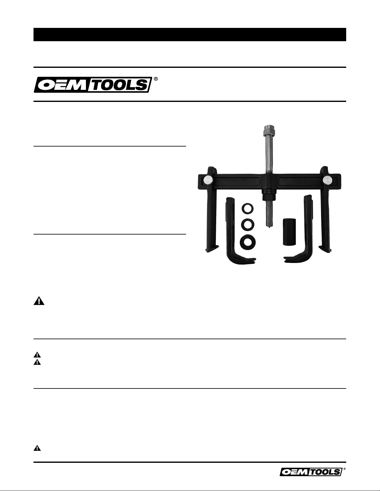
DESCRIPCIÓN DEL PRODUCTO
Diseñado para extraer los tambores y rotores de los frenos en la mayoría
de los vehículos FWD (Tracción Delantera) y AWD (Tracción en las cuatro
ruedas) (y algunos RWD -Tracción trasera). Además se puede usar para
extraer otras piezas grandes, tal como cubos.
ESPECIFICACIONES DEL PRODUCTO
Capacidad de carga 7 Toneladas
Propagación máxima 14" (355 mm)
Máximo alcance tambor / rotor 5.1" (130 mm)
Alcance máximo hub 4.1" (105 mm)
Tornillo de presión (A) hexagonal 1-1/4" (32 mm)
Longitud del tornillo de presión (A) 10.5" (266 mm)
Longitud de la rosca del tornillo de presión (A)
6.25" (158 mm)
Tuerca forzadora (F) hex 1-1/4" (32 mm)
Adaptadores de cubo incluidos
Pequeño (32.8 mm),
Mediano (36.9 mm),
Grande (45 mm)
Impacto clasificado Si
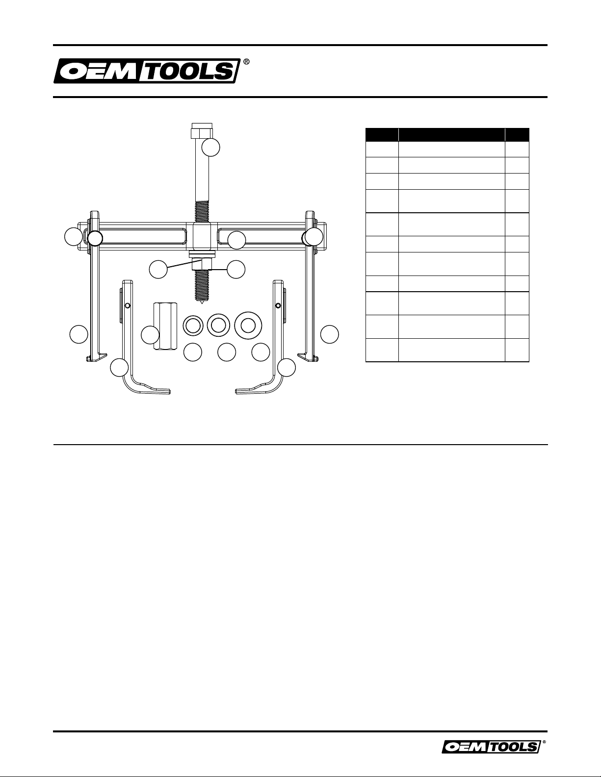
CONTENIDO
(1) La barra en T, (2) Mordazas del extractor (E) de tambor/rotor,
(2) Botones de ajuste (C), (3) Adaptadores de cubo, (2) Arandelas
endurecidas, (1) Tuerca forzadora, (1) Tuerca forzadora extendida, (1)
Tornillo de presión
INSTRUCCIONES Y ADVERTENCIAS
ESPECÍFICAS DE SEGURIDAD
ADVERTENCIA:SIEMPRE consulte el manual de mantenimiento
del vehículo antes de usar.
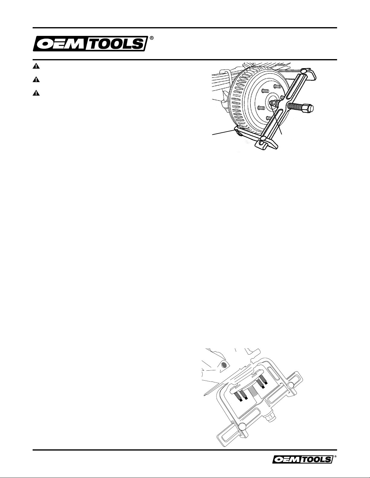
ADVERTENCIA:ANTES de aplicar carga, asegúrese de que las
mordazas del extractor estén derechas y que están haciendo contacto
seguro con la pieza que se está extrayendo. Una carga insegura puede
hacer que la herramienta o la pieza se desprenda inesperadamente,
causando lesión o daños a la propiedad personal.
ADVERTENCIA:Asegúrese de que toda su vestimenta, los
dedos y cualquier otra extremidad no estén colocados entre las mordazas
del extractor y la pieza que está siendo extraída, o entre la piezas que
está siendo extraída y la barra en T.
ADVERTENCIA:SIEMPRE asegúrese de que la carga se coloque
en la dirección correcta antes de la extracción. De lo contrario, puede
dañar la pieza o la herramienta.
ADVERTENCIA:Si se va a usar una correa de trinquete,
asegúrese de que la correa no esté dañada y que no se coloque entre las
mordazas del extractor y la pieza que está siendo extraída, esto puede
causar que el sistema de extracción falle y ocasione lesiones o daños
materiales.
ADVERTENCIA:Si se va a usar una correa de trinquete,
asegúrese de que la correa esté libre de otras piezas.
ADVERTENCIA:Si se va a usar una correa de trinquete,
asegúrese de que la correa no se arrastre en el suelo, ya que esto puede
provocar un peligro de tropiezo.

7
Manual de instrucciones de operación y piezas 25106
8/20
2020 OEMTOOLS®
EXTRACTOR DE CUBO, ROTOR Y
TAMBOR DE SERVICIO PESADO
ADVERTENCIA:SIEMPRE mantenga bien lubricado el tornillo
forzador; use un compuesto antiadherente de alta calidad.
ADVERTENCIA:SIEMPRE use dados y accesorios de impacto
cuando use herramientas neumáticas con esta herramienta.
ADVERTENCIA:Si bien esta herramienta se puede utilizar para
extraer piezas más grandes, como se menciona en la sección sobre el
propósito en este manual, OEMTOOLS®no puede describir todos los
diversos procedimientos necesarios para cualquier situación y aconseja
que el usuario consulte el manual de mantenimiento del vehículo o
contacte a un técnico calificado para asistencia.
EXTRACCIÓN DEL TAMBOR/ROTOR (D) DEL FRENO
1. Consulte el manual de mantenimiento del vehículo antes de usar.
Use el método y dispositivo de elevación recomendados para
levantar el vehículo de manera que la rueda y el neumático estén
elevados.
2. Después de quitar la rueda, vuelva a atornillar por completo dos
tuercas en los espárragos opuestos de la rueda. Afloje 3-4 vueltas
las tuercas del tambor. Esto permite extraer el tambor del cubo,
pero sin que se salga de los espárragos.
3. Centre la barra en T (B) sobre el tambor o rotor que se va a extraer.
Regule los botones de ajuste (C) de modo que las mordazas del
extractor (E) de tambor/rotor (D) estén aseguradas uniformemente
alrededor del tambor/rotor.
4. Engrase las dos arandelas (H), la tuerca forzadora (F) y el tornillo de
presión (A).
5. Enrosque el tornillo de presión (A) en la barra en T (B). Deje espacio
entre el tornillo de presión (A) y el tambor/rotor (D) para agregar las
arandelas (H) y la tuerca forzadora.
6. Enrosque las arandelas (H) en el tornillo de presión (A), en el
interior de la barra en T (B) de cara al tambor/rotor.
7. Enrosque la tuerca forzadora (F) en el tornillo de presión (A), en el
interior de las arandelas (H) de cara al tambor/rotor.
8. Antes de extraer, asegúrese de que los botones de ajuste (C) estén
correctamente ajustados y asegurados, y que el tornillo de presión
(A) esté centrado sobre el eje. Las mordazas del extractor (E) deben
colocarse de la siguiente manera.
a. Frenos de tambor – Entre el tambor del freno y la placa de
apoyo.
b. Frenos de discos – De manera segura contra la parte trasera
del rotor.
9. Si es necesario, se puede usar una correa de trinquete para
envolver las mordazas del extractor (E) de tambor/rotor (D) para
asegurar mejor las mordazas al tambor/rotor. SIEMPRE revise
la correa de trinquete por daños antes de usarla y consulte las
instrucciones de seguridad si usa una correa de trinquete. NO use
la correa como mecanismo para aplicar más fuerza al sistema,
este mecanismo solo se debe usar para sujetar mejor el sistema.
10. Mientras sostiene la tuerca forzadora, apriete a mano el tornillo de
presión (A), de modo que la muesca macho en el tornillo de presión
(A) esté en contacto con la muesca hembra en el eje.
11. La tuerca forzadora (F) y las arandelas (H) deben estar ajustadas
contra la barra en T (B). Con una llave de 1-1/4" o 32 mm,
sostenga la tuerca forzadora (F) en su lugar. Usando una llave
de impacto con un dado de impacto de 1-1/4" o 32 mm, apriete
el tornillo de presión (A). Esto empujará el tornillo de presión (A)
contra el cubo/eje, y reteniendo la tuerca forzadora (F) contra la
barra en T (B), extraiga el tambor/rotor (Figura 1).
12. Si corresponde, retire la correa de trinquete del extractor. Retire el
extractor regulando los botones de ajuste (C) mientras sostiene la
barra en T (B). Retire las tuercas de la rueda y el tambor/rotor.
EXTRACCIÓN DEL CUBO
1. Retire los botones de ajuste (C) de las mordazas del extractor (E) de
tambor/rotor (D) y retire las mordazas de la barra en T (B). Coloque las
mordazas del extractor (E) de cubo en la barra en T (B) de modo que
las mordazas queden dirigidas hacia adentro. Enrosque los botones
de ajuste (C) en las mordazas del extractor (E) de cubo. No los apriete
completamente en su lugar.
2. Engrase las dos arandelas (H), la tuerca forzadora extendida y el
tornillo de presión (A).
3. Inspeccione detrás del cubo para encontrar una plataforma sólida. En
la mayoría de las aplicaciones se puede usar el muñón de dirección.
4. Centre la barra en T (B) sobre el cubo que se va a extraer. Ajuste las
mordazas del extractor (E) de cubo alrededor de la parte trasera del
cubo, de modo que descansen sobre el muñón de la dirección u otra
plataforma sólida. Apriete las mordazas del extractor (E) de cubo en su
lugar usando los botones de ajuste (C).
5. Enrosque las arandelas (H) en el tornillo de presión (A), luego pase el
tornillo de presión (A) a través de la barra en T (B) y el cubo.
6.
Seleccione el adaptador de cubo correcto (I, J, K) que pasará a través
del muñón de la dirección y descansará contra la parte trasera del cubo.
7. Apriete a mano la tuerca forzadora extendida (G) en su lugar. El
extremo hexagonal del tornillo de presión (A) y las arandelas (H)
deben estar ajustados contra la parte superior de la barra en T (B), y el
adaptador del cubo (I, J, K) y la tuerca forzadora extendida (G) deben
estar ajustados contra el cubo. No debe haber juego en el sistema,
asegúrese de que el adaptador del cubo (I, J, K) esté presionando
directamente contra la parte trasera del cubo.
8.
Con una llave de 1-1/4" o 32 mm, sostenga en su lugar la tuerca forzadora
(F) extendida. Usando una llave de impacto con un dado de impacto
de 1-1/4" o 32 mm, apriete el tornillo de presión (A). Las arandelas (H)
presionarán la barra en T (B), las mordazas del extractor (E) de cubo
presionarán contra el muñón de la dirección. El adaptador del cubo (I, J, K)
y la tuerca forzadora extendida (G) presionarán contra la parte trasera del
cubo hasta que el cubo se desprenda del muñón (Figura 2).
Figura 2
Sostenga la tuerca
hexagonal con una
llave de 1.25" o 32 mm
mientras impacta el perno
de transmisión para
enganchar la tracción
Verifique que la mordaza
del extractor tenga un buen
contacto con el tambor de freno
Figura 1

8
Manual de instrucciones de operación y piezas 25106
8/20
2020 OEMTOOLS®
EXTRACTOR DE CUBO, ROTOR Y
TAMBOR DE SERVICIO PESADO
A
B
D D
E
G
I
E
J K
FH
C C
GARANTÍA LIMITADA DE POR VIDA DE OEMTOOLS®
Si durante el tiempo en que usted es propietario de este producto OEMTOOLS®encuentra algún defecto de materiales o de fabricación al
usarlo normalmente y sin incluir el desgaste normal, devuélvalo al lugar donde lo compró, o envíenoslo a OEMTOOLS®para que lo reparemos
o se lo reemplacemos, a criterio nuestro. A fin de obtener este servicio, envíe su herramienta y comprobante de compra, con transporte
prepagado, a OEMTOOLS®Q.A. Dept., 3580 E. Raines Road #3, Memphis, TN 38118. No asumimos responsabilidad por artículos perdidos
o dañados durante el transporte. Por favor asegure su paquete. Si nuestra inspección verifica el defecto, nosotros ya sea repararemos o
reemplazaremos el producto, según sea nuestra opción o podemos optar por reembolsarle el precio de compra si no podemos oportuna y
rápidamente proporcionarle uno de reemplazo. Nosotros pagamos el retorno de los productos reparados, pero si determinamos que no hay
defecto o que el defecto resultó de causas que no están dentro del alcance de nuestra garantía, entonces usted deberá asumir el costo de
retorno del producto.
OEMTOOLS®no garantiza ningún otro producto cuya marca no sea OEM®o OEMTOOLS®. OEMTOOLS®no ofrecerá ninguna garantía por
productos que han sido sometidos a uso anormal. El uso anormal incluye, pero no se limita a, abuso, accidente, modificación, negligencia y
uso o reparaciones no autorizadas o irrazonables. Esta garantía no cubre brocas, hojas, limas, baterías ni calibración. Recomendamos que
usted preste servicio a sus herramientas y afile o reemplace las hojas, brocas, limas y baterías según sea necesario. OEMTOOLS®se reserva el
derecho de modificar la construcción o diseño en cualquier momento, sin ninguna obligación de incorporar tales cambios a las herramientas o
equipos vendidos previamente.
OEMTOOLS®se esfuerza en asegurar de que sus productos cumplen las normas de alta calidad y durabilidad y garantiza al comprador original
que este producto está libre de defectos de material o mano de obra durante un período de seis meses a partir de la fecha de compra. Esta
garantía no se aplica a daño debido directa o indirectamente a mal uso, abuso, negligencia o accidentes, reparaciones o modificaciones
realizadas fuera de nuestra planta, actividad criminal, instalación incorrecta y desgaste normal o falta de mantenimiento.
En ningún caso, seremos responsables por muerte, lesiones a personas o daños materiales o por daños imprevistos, eventuales, especiales
o indirectos que surjan a causa del uso de este producto. En algunos estados no se permite la exclusión o limitación de daños imprevistos o
indirectos, por lo tanto la limitación anterior puede no aplicarse en su caso. ESTA GARANTÍA REEMPLAZA EXPRESAMENTE TODAS LAS OTRAS
GARANTÍAS EXPRESAS O IMPLÍCITAS, INCLUYENDO LAS GARANTÍAS DE COMERCIABILIDAD Y ADECUACIÓN. Esta garantía le otorga derechos
legales específicos y usted también puede tener otros derechos que varían de un estado a otro.
Figura Descripción Cant.
A Tornillo de presión 1
B La barra en T 1
C Botones de ajuste 2
DMordazas del extractor
de tambor/rotor 2
EMordazas del extractor
de cubo 2
F Tuerca forzadora 1
GTuerca forzadora
extendida 1
H Arandelas endurecidas 2
IAdaptador de cubo
pequeño 1
JAdaptador de cubo
mediano 1
KAdaptador de cubo
grande 1
DISEÑO DEL PRODUCT LISTA DE PARTES
Table of contents
Languages:
Other OEM Tools Tools manuals

OEM Tools
OEM Tools 24794 Service manual

OEM Tools
OEM Tools 27400 Service manual

OEM Tools
OEM Tools 27407 Service manual

OEM Tools
OEM Tools 27402 Service manual

OEM Tools
OEM Tools ViperFlex 24424 User manual

OEM Tools
OEM Tools 87030 Service manual

OEM Tools
OEM Tools 24562 Service manual

OEM Tools
OEM Tools 25136 Service manual

OEM Tools
OEM Tools 87009 Service manual

OEM Tools
OEM Tools 25818 Service manual