OFFCARR FENICE User manual

2
INDEX
1. INTRODUCTION..................................................................................................4
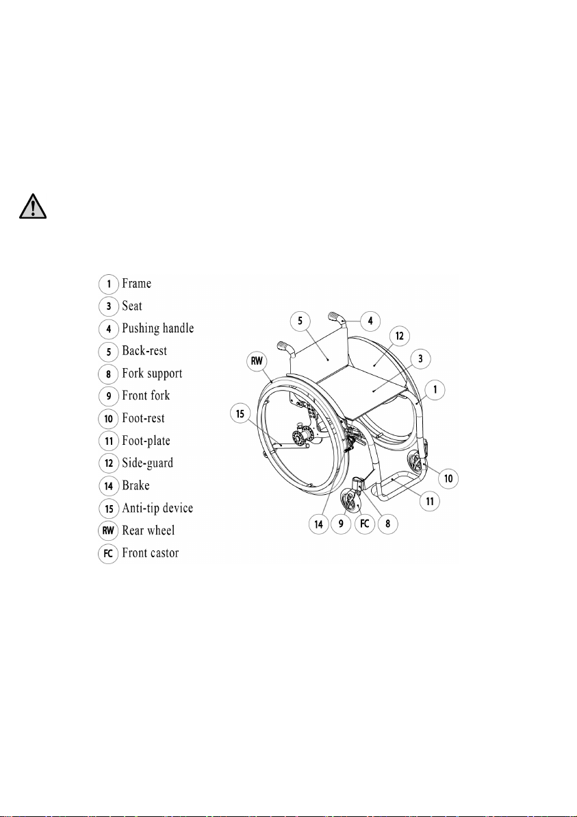
1.1 DESCRIPTION ............................................................................................................................. 4
1.2 FEATURES .................................................................................................................................. 5
2. PREPARATION FOR USE .....................................................................................6
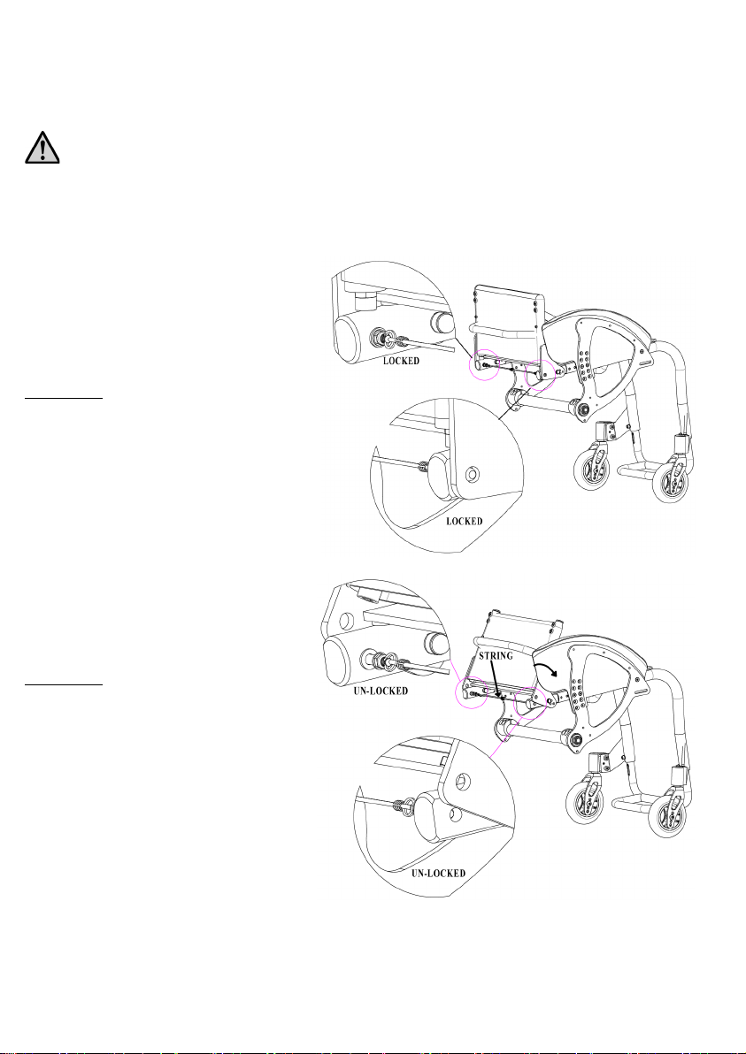
2.1 BACK-REST OPENING/FOLDING .................................................................................................. 6
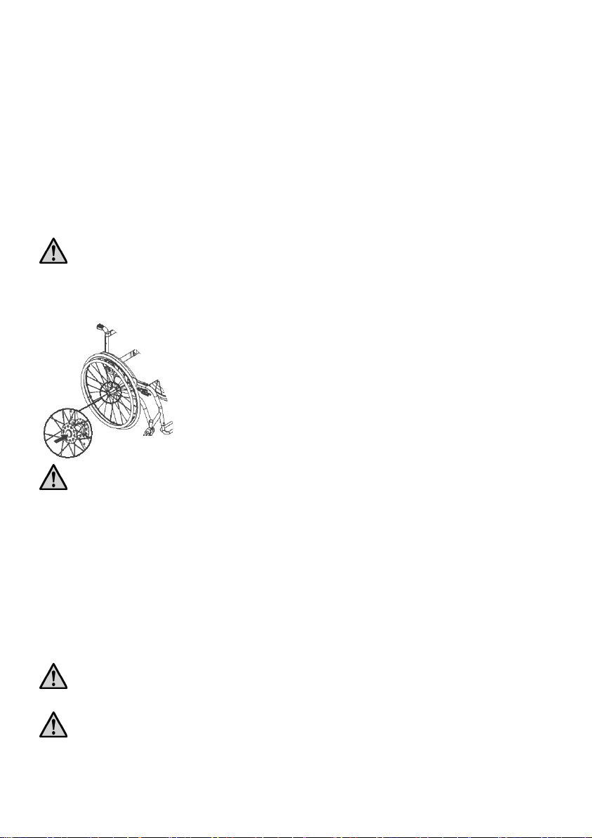
2.2 REAR WHEELS ASSEMBLY AND RELEASE.................................................................................... 7
2.3 TYRE PRESSURE CHECK .............................................................................................................. 7
2.4 CHECKING THE BRAKES ............................................................................................................. 8
2.5 CHECKING THE ACCESSORIES..................................................................................................... 8
3. SETTING UP ........................................................................................................9
3.1 SEAT DEPTH ADJUSTMENT.......................................................................................................... 9
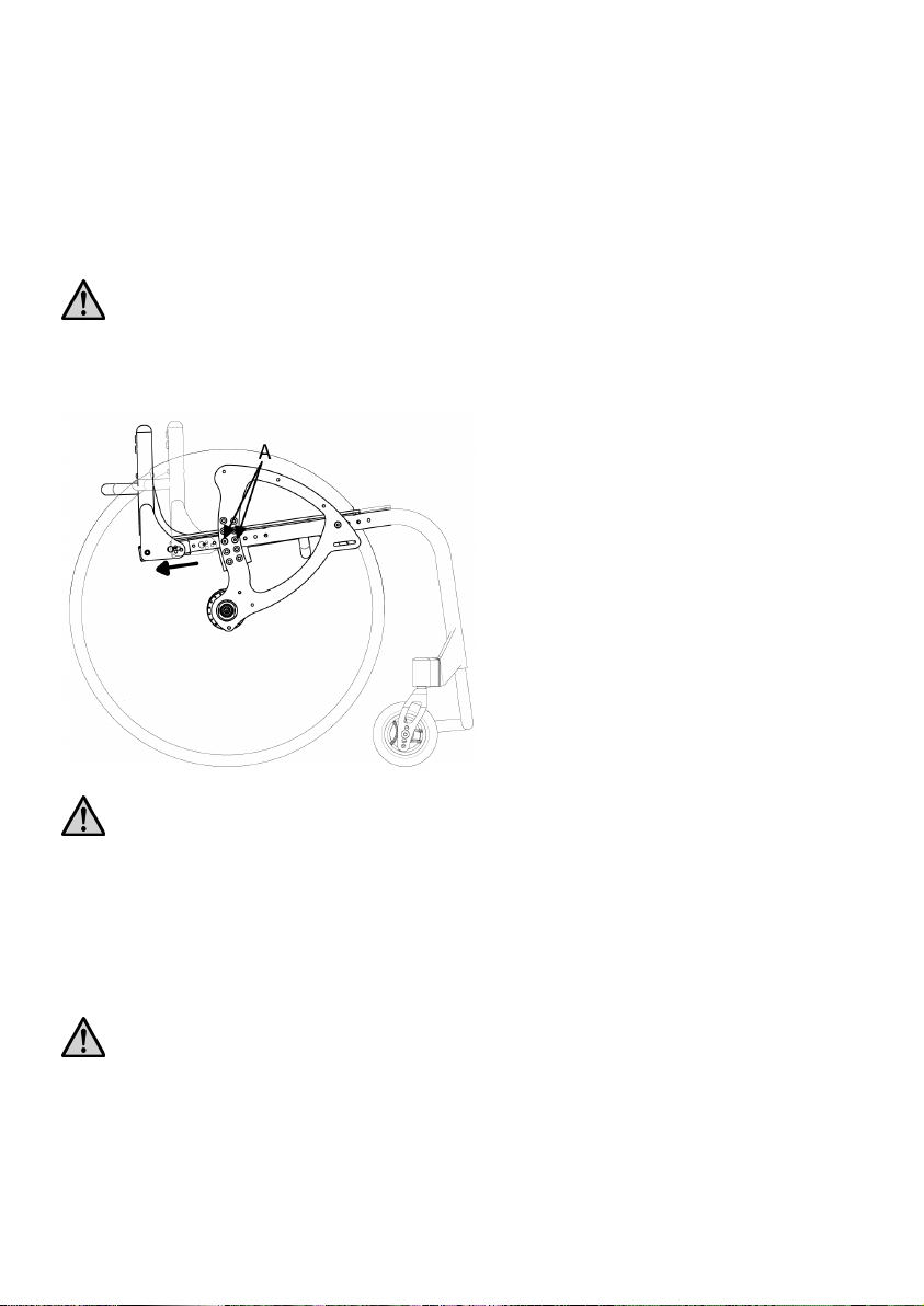
3.2 GRAVITY CENTRE ADJUSTMENT ................................................................................................. 9
3.3 REAR SEAT HEIGHT ADJUSTMENT............................................................................................. 11
3.4 FRONT SEAT HEIGHT ADJUSTMENT........................................................................................... 11
3.5 FRONT CASTOR REPLACEMENT ................................................................................................ 12
3.6 REAL WHEEL CAMBER ADJUSTMENT ........................................................................................ 13
3.7 FRONT FORK SUPPORT PLATE ASDJUSTMENT............................................................................ 14
3.8 BACK-REST TILT ADJUSTMENT ................................................................................................. 14
3.9 BACKREST HEIGHT ADJUSTMENT ............................................................................................. 15
3.10 HEIGHT ADJUSTABLE PUSHING HANDLES ................................................................................. 15
3.11 BACKREST TENSION ADJUSTMENT ........................................................................................... 16
3.12 FOOTPLATE TO SEAT DISTANCE ADJUSTMENT .......................................................................... 16
3.13 BRAKE SETUP AND MAINTENANCE ........................................................................................... 17
4. ANTI-TIP DEVICES............................................................................................18
5.1 USE OF THE REVOLVING ANTI-TIP DEVICE ................................................................................ 18
5.2 ADJUSTMENT OF THE ANTI-TIP DEVICE .................................................................................... 19
5.2.1 Adjustment through the rotation of the support plate........................................................ 19
5.2.2 Anti-tip device terminal adjustment.................................................................................. 19
5. UNBALANCING SYSTEM ...................................................................................19
6. ARMRESTS........................................................................................................20
7. CUSHION ..........................................................................................................21
8. SPOKES GUARDS..............................................................................................21
9. USE OF THE WHEELCHAIR...............................................................................21
10. WARNING TO REDUCE THE RISKS ASSOCIATED WITH MISUSE OF THE WHEELCHAIR23
11. MAINTENANCE, INSPECTIONS AND CONTROLS ...............................................24
12. CLEANING INSTRUCTRION...............................................................................25
13. TECHNICAL SERVICE .......................................................................................26
14. WARRANTY TERMS ..........................................................................................26
15. PACKAGING, SHIPPING AND DELIVERY ...........................................................27
16. MATERIALS DIFFERENTIATION .......................................................................27

3
Thanks for choosing an OFF CARR wheelchair.
Since 1982 OFF CARR listens and responds to the customers' needs by
developing highly innovative and technologic solutions, always aimed to
reduce daily mobility problems, with special attention to product style and to
improve customers' life quality.
OFF CARR has a certified system for quality management following UNI
EN ISO 9001:2015 regulations and a Medical device - Quality management
system following UNI EN ISO 13485:2016 regulations.
OFF CARR products meet the the MDR 2017/745 requirements.
Before using or making adjustments on this device, carefully
read the content of this instruction manual.
If needed, please contact an authorized dealer or the manufacturer at the
following address:
OFF CARR s.r.l.
Via dell’Artigianato II, 29
35010 Villa del Conte (Padova) Italy
Tel. +39 049 9325733 Fax +39 049 9325734
E-mail: offcarr@offcarr.com http://www.offcarr.com

4
1. Introduction
The ultra lightweight wheelchair FENICE is a non-intrusive medical device, specifically
designed to reduce and counterbalance a physical handicap.
This wheelchair is manually propelled on the back wheels, it has many setups and a wide
range of accessories that meet any customer need.
Only qualified operators must setup the device.
It is forbidden to use the wheelchairs or parts of them in different ways from those
described on this manual.
1.1 Description
FENICE is an aluminium rigid frame wheelchair. Other details are made with composite
materials, such as carbon fibre, titanium, aluminium or steel alloys. Various frame colours are
available and can be combined with various coloured anodized accessories and details sets.
The seat upholstery (3) and the backrest (5) are usually made with black nylon cloth. The
backrest can be also made with breathable material to increase the customer comfort.
A comfortable compartment with closing zip can be added in the lower part of the backrest
and another can be placed frontally under the seat. The backrest is adjustable in height by
acting on the frame-fixing screws.
The backrest is tilt adjustable and can be folded down to reduce the wheelchair size during

5
transport operations. The backrest upholstery is easily removable to make the cleaning and
washing operations easier and its straightening is adjustable by acting on the velstraps under
the upholstery. Its height is adjustable.
The rear wheels (RW) are equipped with quick releasing axles.
The front forks (9) have adjustable angles and can lodge various wheel diameters (FC) at
various height, to better answer the setup and agility needs of users.
Considering possible setup restrictions, the foot-plate (11) can be single or double and
adjustable in height.
The wheelchair is provided with carbon fibre sideguards (12) or with optional aluminium or
composite polymer sideguards, as chosen on the order form.
The wheelchair can be also configured with “L” shaped tip-up armrests or detachable ones
with an adjustable high from 22 up to 28 cm.
The brake devices (14) are available in standard or scissor model and are adjustable to
counterbalance different wheel sizes and different wheel setups.
The wide and complete range of accessories available, allows a complete customisation of
FENICE both aesthetically and functionally.
1.2 Features
Aluminium rigid frame
Adjustable user balance and seat set up
Tilt adjustable front fork
Tilt adjustable and foldable backrest
Carbon fibre side-guards
Maximum load of 120 Kg
The order form allows different setups and various combinations of accessories.

6
2. Preparation for use
The preparation for use of these devices must be performed by qualified
personnel both to evaluate the suitability of the product and to provide the
correct instructions to the user.
2.1 Back-rest opening/folding
OPENING
•Pull on the back-
rest until the rear locks
reach their locking places
FOLDING
•Pull the string to un-lock the back-rest and
push it down

7
2.2 Rear wheels assembly and release
FENICE wheelchairs are normally shipped with the rear wheels aside.
It is possible to assemble or release the wheels as follows:
• ensure the brakes are released;
• insert the axle into the wheel by holding down the button;
• keeping the axle button pressed insert it into the bush on the frame of the wheelchair;
• release the button;
• check the efficiency of the engagement by trying to pull out the wheel without pressing the
button and making sure it does not come off.
It is suggested to verify the proper assembly and the efficiency of the quick
release axle before using the wheelchair and always after performing releasing
and assembly of the rear wheels to the frame.
Test for the right functioning of the quick release axle and proper assembly of the rear wheels:
•ensure the brakes are released;
•keeping the axle
button pressed, pull out the wheel
from the hub;
•still holding down the axle button,
insert it into the
hub on the frame of the wheelchair;
•check the efficiency of the engagement
by trying to
pull out the wheel without pressing the button and
making sure it does not come off.
For safety reasons it is important to repeat this test every time that for transport
or maintenance reasons, the rear wheels are removed and reassembled to the
frame.
2.3 Tyre pressure check
A periodical check of the tyre pressure may help to keep the wheelchair efficient and more
comfortable.
Verify the tyre pressure value according to the value marked on the tyre. (Indicatively the
maximum pressure is: 7.5 BAR for high pressure rear wheels, 4.5 BAR for 20'', 22'', 24'' x1.3 /
8 wheels and 2.5 BAR for pneumatic front castors.)
The pressure for the model Schwalbe Marathon Plus should always be kept from a
minimum of 7 BAR to a maximum of 9 BAR to prevent damage to the surface of the tyre
itself.
In case of air transport is recommended to decrease the tire pressure.

8
2.4 Checking the brakes
To check the correct functioning and the efficiency of the parking brakes act as following:
•activate the brake (Fig. P, S, U);
•check if the wheels are blocked.
The included brakes, except for
optional drum brakes, have to
be used only a
s parking brakes and
never to de
crease the speed of the
wheelchair while moving.
To ensure the efficiency of the brakes it
is necessary to maintain the proper tyre
pressure and check frequently the wear
of the clamping elements.
Pushing brake “OFF”
position
Pushing brake “ON”
position
Pulling brake “OFF”
position
Pulling brake “ON”
position
Scissor brake “OFF”
position
Scissor brake “ON”
position
2.5 Checking the accessories
Any accessory required at the time of the setup of the wheelchair is to be shipped separately.
If so they should be properly installed before using the wheelchair.
Fig. P
Fig. O
Fig.
Fig, S
Fig. T
Fig. U

9
3. Setting up
The wheelchair is shipped in the setup chosen on the order form. The selected options in the
order form should ensure the best possible setup to match the customer needs. Considering
potential setup restrictions it is still possible to perform other adjustment to better fit the user’s
needs.
Please refer to authorized and qualified personnel only to perform any type of
adjustment on the wheelchair.
3.1 Seat depth adjustment
When necessary is possible increase seat
depth of 2-4-6cm:
•u
nscrew completely and remove the
“A” screws;
•move the telescopic insert until
reaching the desired depth (the
extension insert is already pre-holed
with steps of 2 cm);
•fix the “A” screws.
The operations always have to be
performed symmetrically (both on right
and left side)
Changing the seat depth also changes the position of rear wheel axle.
The further the rear wheels axes are assembled, the more active and agile the wheelchair
becomes, but at the same time the stability is reduced.
The more the rear wheel axes are assembled to the back, the more stable the wheelchair is,
but the most effort is required to push it.
3.2 Gravity centre adjustment
The further the rear wheels axes are assembled, the more active and agile the wheelchair
becomes, but at the same time the stability is reduced.
The more the rear wheel axes are assembled to the back, the more stable the wheelchair is,
but the most effort is required to push it.
The position of the rear wheel axle can be adjusted:
1. By acting on the screws “A” and “B” that fix the SHS holder to the frame

10
2. By changing the seat depth
1-acting on the screws “A” and “B”
that fix SHS holder to the frame:
•unscrew completely and remove the
screws “A” and “B”;
•c
hange the rear axle position moving
the SHS holder;
•fix the “A” and “B” screws.
Operations on the SHS holder have
always to be performed symmetrically
(both on left and right side).
Asymmetrical comb
inations produce
instability
2- changing the seat depth
•u
nscrew completely and remove the
“A” screws;
•move the telescopic insert un
til the
desired depth (the extension insert is
already pre-
holed with steps of 2
cm);
•fix the “A” screws.
The operations
always have to be
performed symm
etrically (both on right
and left side)
•Pay attention to the proper camber adjustments before fixing tightly the wheel bushes
(see par 3.6);
•connect again the wheels to the chair checking the proper assembly (see par.2.2);
•changing the gravity centre is an operation that always has to be performed
symmetrically.
Be sure to choose the same position in both wheel bushes on the back of the frame.
Asymmetrical combinations produce instability.
Once changed the position of the back wheels, it is essential to adjust the front forks
perpendicularity (see. par.3.7), the proper camber of the rear wheel (see par.3.6), and the
positioning of the parking brakes (see par.3.13).
Note: consider that the further the hub is connected, the more agile the wheelchair is, and the
further back it is assembled, the less active but the safest the wheelchair becomes.

11
3.3 Rear seat height adjustment
The rear seat height can be adjusted by
acting on the “A” and “B” screws that
fix the SHS holder to the frame:
•unscrew without rem
oving the “B”
screw;
•c
ompletely unscrew and remove the
“A” screws;
•c
hange the rear seat height by
modifying the position of the SHS
holder;
•screw back the “A” and “B” screws.
•o
perations on the rear seat height
have always t
o be performed
symmetrically.
Be sure to choose the same position in both wheel bushes on the back of the frame.
Asymmetrical combinations produce instability.
Once changed the position of the back wheels, it is essential to adjust the front fork
perpendicularity (see. par.3.7), the proper camber of the rear wheel (see par.3.6), and the
positioning of the parking brakes (see par.3.13).
3.4 Front seat height adjustment
The front wheelchair height can be set:
1. By changing the diameter of the front wheels
2. By choosing a different position of the wheel on the fork
3. By changing the fork shaft (different length)
Changing the diameter of the front wheels or choosing a
different position of the wheel in the fork:
•completely unscrew one of the “D” screws and remove
the “E” pin on the side of the non-
removed “D” screw,
being careful to where the “F” spacers are;
•if necessary, change the wheel;
•p
osition the wheel hole at the same level of the most
suitable fork hole;
•insert the “E” pin, being careful not to move the “F” spacers from their
original positioning;
•fix the “D” screw.

12
Changing the fork shaft (different length):
•remove the protection cap;
•unscrew the “G” nut;
•unscrew the “M” nut and the “L” washer;
•replace the shaft;
•insert the new shaft and fix the
“G” and “M” nuts,
being careful
to the correct positioning of the “L”
washer.
3.5 Front castor replacement
If necessary, the front castor can be replaced:
•completely unscrew one of the “D” screws and
remove the “E” pin on the side of the non-removed
“D” screw, being careful to where t
he “F” spacers
are;
•if necessary, change the wheel;
•p
osition the wheel hole at the same level of the
most suitable fork hole;
•insert the “E” pin, being careful not to move the “F” spacers from their
original positioning;
•
fix the “D” screw.
Be sure to choose the same position for both castors. Asymmetrical combinations
produce instability.
Be careful not to change the front seat height while changing the front castors.

13
3.6 Real wheel camber adjustment
The rear wheel camber is fixed according with the choice on the order form. However is
possible to change it if required.
On FENICE wheelchairs it is possible to change the wheel camber by replacing the rear
bushes as follow:
•remove the rear wheels (see par.2.2);
•unscrew without removing the “N” screws”;
•unscrew without removing the “P” screws”;
•replace the camber bush with a new one with the desired camber;
•place the camber bush
with the camber in the correct direction and with the
two flat surfaces approximately perpendicular to the ground;
•insert the rear wheels and check the
distances between them (d1and d2),
measured on the front and on the back
at the level of the hub as shown in the
figure: d1 and d2 have to be equal.
•check the “c
” distance from frame to
wheel and verify if it is equal bot
h on
the left and on the right side;
•once the necessary corrections have been performed and all the above tests are
passed, tighten properly the “N” screws and the “P” screw.

14
3.7 Front fork support plate adjustment
Once the front and rear seat heights are set, it is necessary to test and to adjust the
perpendicularity of the front fork support plate. This adjustment is important to reach the
maximum agility and the best driving sensitivity of the wheelchair.
•remove the protective cap;
•loosen the two “R” screws that secure the fork support
plate;
•rotate the upper eccentric nut until the plate reaches the
perpendicular position;
•tighten the two “R” screws;
•put the protective cap back in place.
Note: the two eccentric nuts have different profiles. The upper nut with round profile allows a
continuous adjustment of the plate perpendicularity. In the lower position the
hexagonal profile eccentric nut is assembled. It is suggested to rotate it only when the
rotation of the upper nut on its own is not enough to reach the correct position.
3.8 Back-rest tilt adjustment
FENICE wheelchair allows 4 backrest tilt positions; they can be set as follows:
•unscrew completely and remove the “S” screws;
•position the back-rest choosing between the holes “H1”
and “H2”;
•fix the “S” screw;
•adjust the rear “T” nut and screw to make sure that, when
the backrest is opened (see par.2.1) the screw strikes on the
frame.

15
3.9 Backrest height adjustment
The backrest height will be chosen during assembly according to the order form selection. It is
however possible to change it over time.
If the wheelchair is equipped with pushing handles is possible to move them up or down of a
few centimetres as shown:
•remove the upholstery cover and open the tension belts
to reach the “A” fixing screws;
•remove the “A” screws;
•move the push-
handle extensions up or down until the
desired height is reached (the extension tubes are
already pre-holed with steps of 2cm);
•insert again the “A” screws and tighten them properly;
•close the belts with the correct tension and fold the upholstery cover over (see
par.3.11).
The same method can be also followed if the pushing
handles are height adjustable.
The same
procedure can be also followed to change the
extended backrest tubes when the wheelchair
is set up
without pushing-handles.
3.10 Height adjustable pushing handles
If the wheelchair is equipped with height adjustable pushing
handles it is possible to adjust them as follow:
•loosen the clamp unscrewing the “B” knob;
•choose the most suitable position for the push-handle;
•tighten the “B” knob properly;
•turn the “B” knob in an appropriate position.
Note: the “B” knob is a special spring lever. To change its position it is possible to pull out
the lever, turn it in the desired position and release it again.

16
3.11 Backrest tension adjustment
The backrest tension can be adjusted by acting on the
velstraps:
•remove the upholstery cover of the backrest;
•a
djust the upholstery tension by opening or closing the
velstraps under the upholstery;
•put the uphols
tery cover back in position, referring to
the rear side of the backrest and eventually place on the
seat the length of cover in excess.
The “V” belts adjusting the backrest tension cannot be excessively tight in order to avoid
deforming the shape of the wheelchair frame.
3.12 Footplate to seat distance adjustment
The telescopic footplate support is inserted into the front
frame of the wheelchair and secured through the “U” screw.
•unscrew and remove the “U” screws;
•remove the foot-rest from the frame;
•unscrew the “Z” screws that fix the inserts to the foot-
rest;
•position the inserts at the correct height;
•fix the “Z” screws;
•insert again and tighten properly the “U” screws.

17
3.13 Brake setup and maintenance
The supplied brakes are designed for parking only and they are not suitable to
reduce the wheelchair speed in any way.
If the rear wheel position has been changed from its original one, it is necessary to proceed
with the brake adjustment. FENICE wheelchair can be equipped with classic pushing or
pulling brakes or scissor brakes.
Act as follow to adjust the brake position:
•leave the brake in OFF position (see par. 2.4 fig. O, R or T);
lLoosen without removing the “W” screws that fix the brake support to the wheelchair
frame.
Classic brake:
•mov
e the brake on its support until the
knurled pin is about 10 mm far from the
tyre;
•m
aintaining the knurled pin perpendicular
to the tyre, properly tighten the “W”
screws;
•i
f the knurled pin appears worn in the
contact area w
ith the tyre, it is possible to
turn it to find a better contact area
or to
change it with a new one.
Scissor brakes:
•p
ut the brake in ON position (see par. 2.4
fig. U)
•m
ove the brake along its support until it
touches the tyre;
•return the brake in O
FF position (see par.
2.4 fig. T) and move the brake of 3-4mm in
the wheel direction, then properly tighten
the “W” screws
•verify the efficiency of the brake (see par.
2.4) and if necessary repeat the adjustment
procedure.

18
4. Anti-tip devices
FENICE wheelchair can be equipped with left and/or right anti-tip devices.
Never use the anti-tip wheels as transit wheels.
5.1 Use of the revolving anti-tip device
When not in use the anti-tip wheel is positioned under the frame:
To activate the anti-tip device it is necessary to push it downwards and rotate it to the back
until it is locked in the correct position.

19
5.2 Adjustment of the anti-tip device
The positioning of the anti-tip is defined during the assembly. However it is possible to
change its distance from ground if necessary.
5.2.1 Adjustment through the rotation of the support plate
•Loosen without removing the “A” screws;
•rotate the anti-
tip support until the desired distance of the
small wheel from the ground is reached;
•properly tighten the “A” screws.
5.2.2 Anti-tip device terminal adjustment
•Remove the “B” screw;
•move the telescopic end terminal until the small wheel is in
the correct position;
•insert the “B” screw and fix it properly.
5. Unbalancing system
On FENICE wheelchair it is possible to assemble the unbalance
pedal. It may be necessary to help assistants to overcome steps or to
facilitate the movement on gravel.
The unbalancing pedal is connected to the frame using the holes
available on the SHS holder.
To adjust the unbalancing pedal position:
•loosen without removing the “A” screws;
•rotate the pedal;
•properly tighten the “A” screws.
NOTE: the unbalancing pedal cannot be assembled on the same side of the frame together
with an anti-tip device.

20
6. Armrests
FENICE wheelchair can be equipped with “L” model tip-up detachable armrests.
The armrests are not designed to lift up the wheelchair both with and without
user.
Usually the armrest is 22 cm height
from the seat. On FENICE the L type
armrest can be heightened of
2 or 4 cm
to increase the comfort of the user, to do
this:
•remove the “B” screw;
•s
elect the desired height and insert
the screw previously removed;
•properly tighten the “B” screw.
The armrest can be detached as follow:
•unscrew without remov
ing the “C”
wing screws;
•detach the armrest by pulling it up.
Remember to fix the “C” wing
screw when the armrest is
positioned on the wheelchair
The “L” armrest can be tip-up.
Table of contents
Other OFFCARR Wheelchair manuals

OFFCARR
OFFCARR ASSIST User manual

OFFCARR
OFFCARR TOP SPIN User manual

OFFCARR
OFFCARR RUBY User manual

OFFCARR
OFFCARR DIVA User manual

OFFCARR
OFFCARR QUASAR User manual

OFFCARR
OFFCARR Althea User manual

OFFCARR
OFFCARR IDRA 2.0 User manual

OFFCARR
OFFCARR QPX-AL User manual

OFFCARR
OFFCARR Althea User manual

OFFCARR
OFFCARR COSTA User manual