OFFCARR DIVA User manual

1
INDEX
1.INTRODUCTION .........................................................................................4
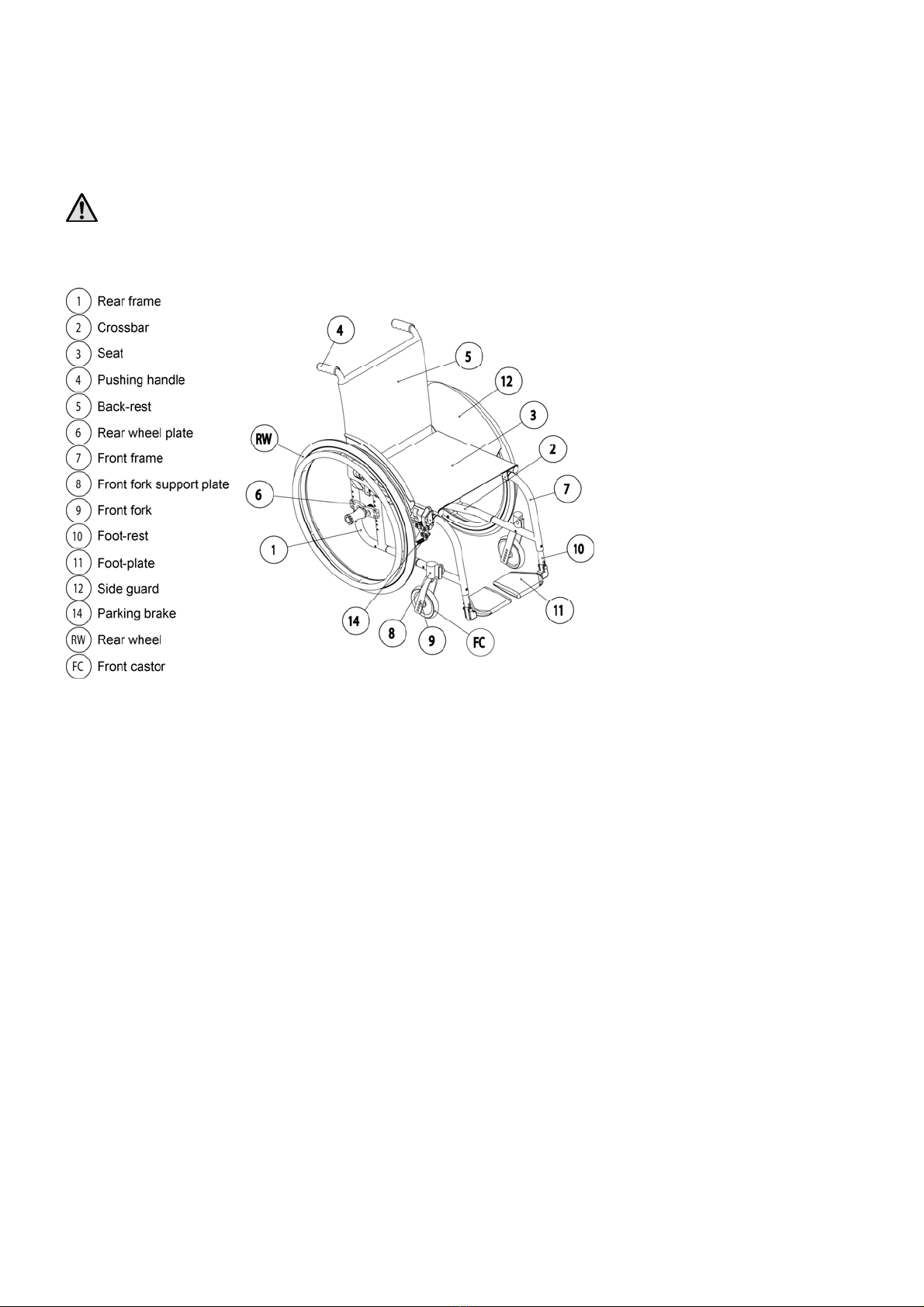
1.1DESCRIPTION .........................................................................................4
1.2FEATURES ..............................................................................................6
2.PREPARATION FOR USE..........................................................................6
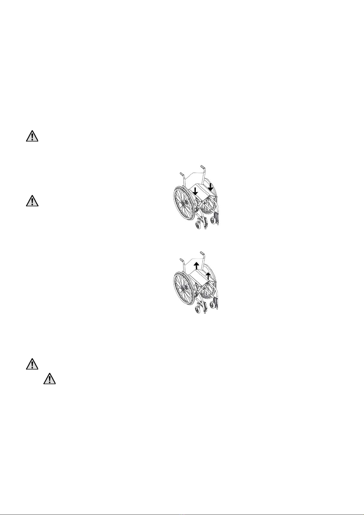
2.1WHEELCHAIR OPENING ..........................................................................6
2.2WHEELCHAIR FOLDING ..........................................................................6
2.3TYRE PRESSURE CHECK..........................................................................6
2.4REAR WHEELS ASSEMBLY CHECK...........................................................6
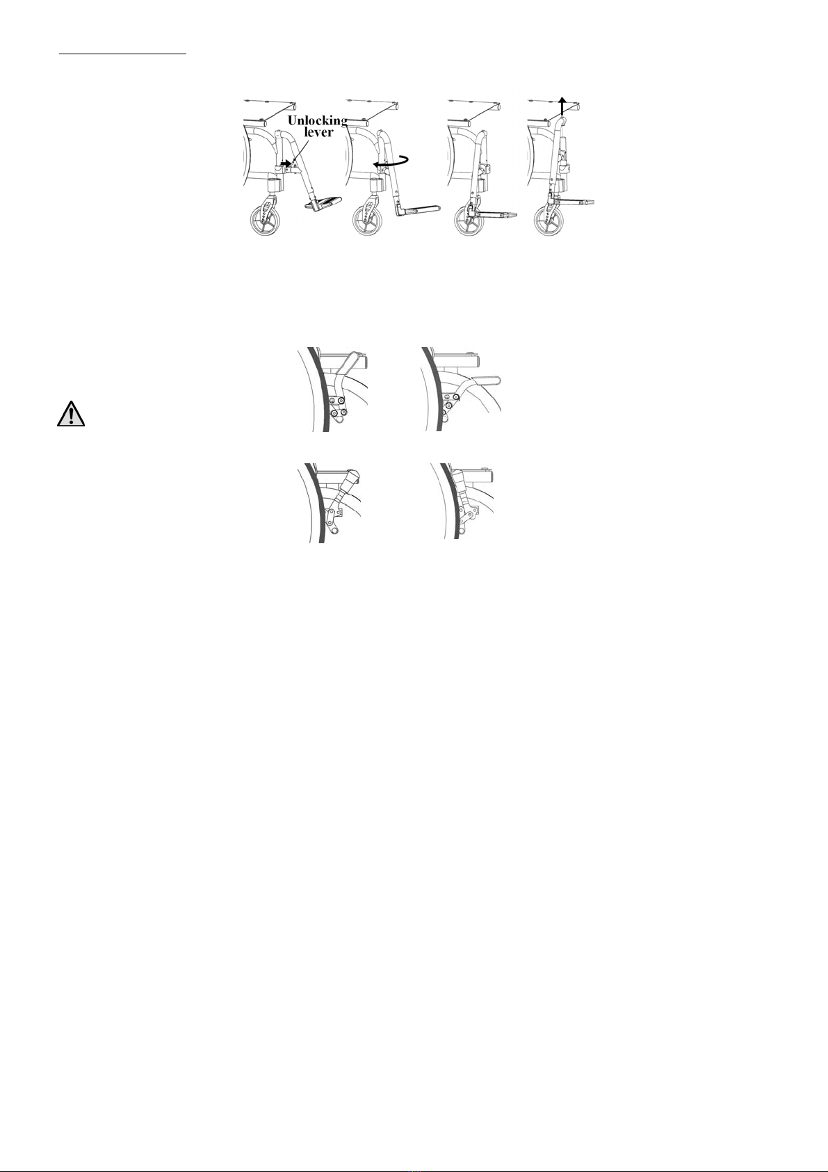
2.5FOOT-REST POSITIONING........................................................................8
2.6BRAKES CHECK......................................................................................9
2.7ACCESSORIES CHECK .............................................................................9
3.SETTING UP...............................................................................................10
3.1REAR SEAT HEIGHT ADJUSTMENT.........................................................10
3.2GRAVITY CENTRE ADJUSTMENT...........................................................10
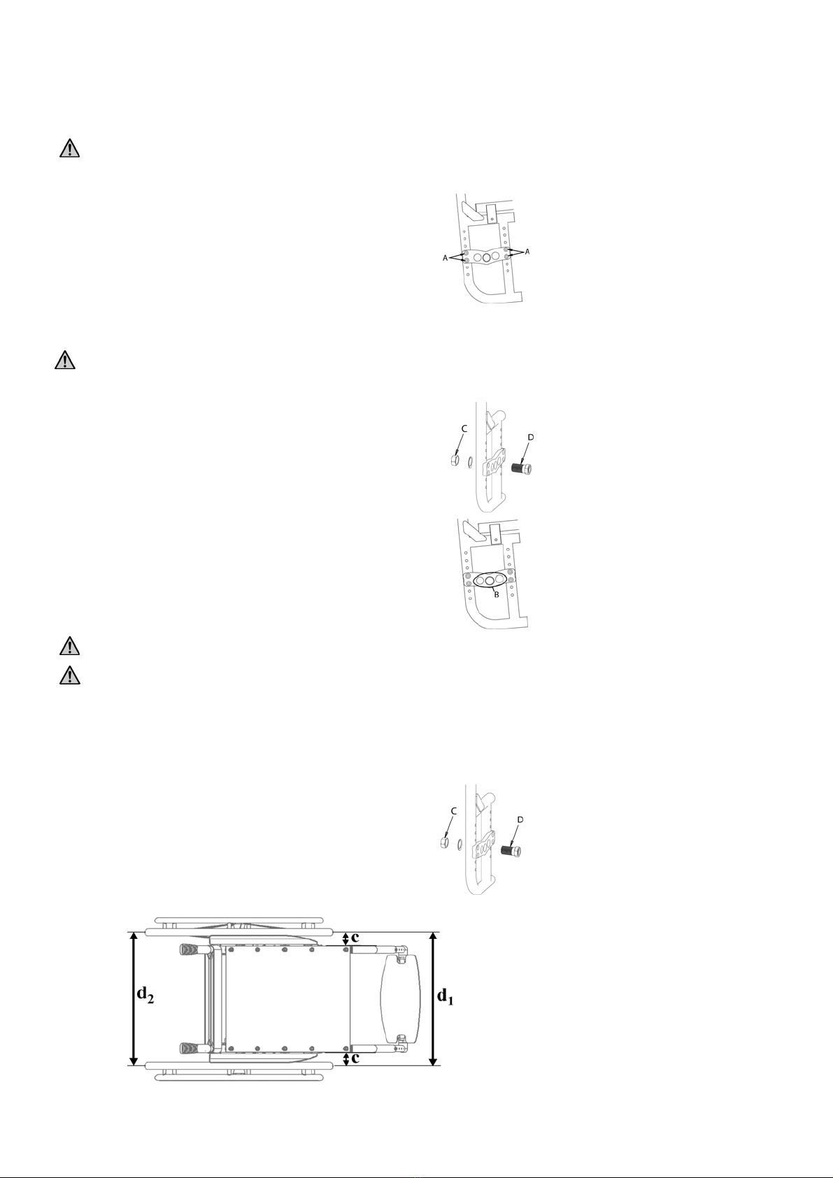
3.3REAR WHEEL CHAMBER ADJUSTMENT..................................................10
3.4FRONT SEAT HEIGHT ADJUSTMENT.......................................................12
3.5FRONT FORK SUPPORT PLATE ADJUSTMENT .........................................12
3.6BACK-REST TILT ADJUSTMENT.............................................................13
3.7SIDE GUARD ADJUSTMENT ...................................................................13
3.8BRAKES ADJUSTMENT AND MAINTENANCE ..........................................14
3.9SEAT UPHOLSTERY ADJUSTMENT AN REPLACEMENT............................14
3.10BACK-REST TENSION ADJUSTMENT ......................................................14
3.11BACK-REST HEIGHT ADJUSTMENT........................................................15
3.12HEIGHT ADJUSTABLE PUSHING HANDLES .............................................15
3.13FOOT-PLATE TO SEAT DISTANCE ADJUSTMENT.....................................15
3.14FOOT-PLATE TILT ADJUSTMENT ...........................................................15
4.ARM-REST..................................................................................................15
4.1DETACHABLE ARM-REST......................................................................17
4.2TIP-UP ARM-REST.................................................................................17
4.3HEIGHT ADJUSTABLE ARM-REST ..........................................................17
4.4“L” TYPE ARM-REST.............................................................................18
5.ANTI-TIP DEVICE.....................................................................................19
5.1CURVED REAR FRAME ANTI-TIP DEVICE ...............................................19
5.2CURVED REAR FRAME ANTI-TIP DEVICE ...............................................20
5.2.1Curved rear frame anti-tip device adjustment...........................20
5.2.2Telescopic end terminal adjustment...........................................20
5.3STRAIGHT REAR FRAME ANTI-TIP DEVICE.............................................20
5.3.1.Height adjustment anti-tip device..............................................21
6.DOUBLE PUSHRIM SINGLE DRIVE.....................................................22
7.HINGED BACK-REST...............................................................................23
8.SMALL WHEEL FOR NARROW PASSAGES WITH LEVER............23
9.UNBALANCING SYSTEM........................................................................24
10.EXTENDED WHEEL PLATE...................................................................24
11.STRETCHED BAR .....................................................................................24
12.TABLE..........................................................................................................24
13.ABDUCTOR ................................................................................................26
14.LATERAL SUPPORT ................................................................................27
15.HEAD-REST................................................................................................27
16.SPOKES GUARDS......................................................................................28
17.WC SEAT.....................................................................................................28
18.USE OF THE WHEELCHAIR ..................................................................29

2
19.WARNING TO REDUCE THE RISKS ASSOCIATED WITH MISUSE OF THE WHEELCHAIR 31
20.MAINTENANCE, INSPECTIONS AND CONTROLS...........................32
21.CLEANING INSTRUCTRION..................................................................34
22.TECHNICAL SERVICE.............................................................................35
23.WARRANTY TERMS................................................................................35
24.PACKAGING, SHIPPING AND DELIVERY..........................................36
25.MATERIALS DIFFERENTIATION.........................................................36

3
Thanks for choosing an OFF CARR wheelchair.
Since 1982 OFF CARR answers the customers' needs by developing highly innovative and technologic
solutions, always aimed at reducing daily mobility problems, with special attention to product style and to
improve customers' life quality.
OFF CARR has a certified system for quality management following UNI EN ISO 9001:2008 regulations
and a Medical device - Quality management system following UNI EN ISO 13485:2012 regulations.
OFF CARR products meet the 93/42/CEE directives, upgraded with the 2007/47/CE directive.
Before using or making adjustments on this device, carefully read the content of this
instruction manual.
If needed, please contact an authorized dealer or the manufacturer at the following address:
OFF CARR s.r.l.
Via dell’Artigianato II, 29
35010 Villa del Conte (Padova) Italy
Tel. +39 049 9325733 Fax +39 049 9325734

4
1. Introduction
The ultra-lightweight wheelchair DIVA is a non-intrusive medical device, specifically designed to reduce and counterbalance a
physical handicap.
This wheelchair is manually propelled on the back wheels, has many setups and a wide range of accessories that meet any
customer need.
Only qualified operators must setup the device.
It is forbidden to use the wheelchairs or parts of them in different ways from those described on this manual.
1.1 Description
DIVA is an aluminium folding frame wheelchair. Other details are made with aluminium, steel alloys or composite materials,
such as carbon fibre.
Various frame colors are available and can be combined with various anodized accessories and details sets.

5
The seat upholstery (3) and the back-rest (5) are usually made of black nylon cloth. The back-rest can be also made of
breathable material to increase the customer’s comfort. The back-rest upholstery is easily removable to make the cleaning and
washing operations easier and its straightening is adjustable by acting on the velstraps under the upholstery.
A comfortable compartment with closing zip can be added in the lower part of the back-rest and another can be placed frontally
under the seat.
The back-rest is adjustable in height by acting on the frame-fixing screws. On request, the wheelchair can be equipped with a
tilt-adjustable back-rest.
Different rear frame shapes are available (with setup limitations). The rear wheel plate (6) allows an easier adjustment of the
rear wheel position to find the most comfortable setup for the user. On demand, for special needs, the wheelchair can be
equipped with an extended wheel plate for safer setup. In this case, the reclining back-rest is compulsory.
20” or 22”or 24” rear wheel (RW) are available, with some setup restrictions. All rear wheels are equipped with the quick
releasing axle.
The front forks (9) have adjustable angles and can hold various wheel diameters (FC) at various heights, to better answer the
setup and agility needs of all users.
The front frame (7) is available with fixed or detachable foot-rests. Considering possible setup restrictions, the foot-plates (11)
can be single or double and adjustable in height and angle. Foot-holding belts and heel stops are available.
The wheelchair can be equipped with closed arm-rests or with open arm-rests with side guards. Different kind of arm-rests are
available. With open arm-rests or without arm-rests the wheelchair is provided with composite polymer side guards or with
aluminium side guards, as chosen on the order form.
The brake devices (14) are adjustable to counterbalance different wheel sizes and different wheel setups.
The wide and complete range of accessories available, allows a complete customization of DIVA, both aesthetically and
functionally.

6
1.2 Features
Ultra-lightweight wheelchair
Aluminium folding frame
Single or double crossbar
Tilt adjustable back-rest
Multiple positions for rear wheels
Tilt adjustable front fork support
Different kind of side guards and arm-rests
Fixed or detachable foot-rests
Single drive available
Maximum load of 120 kg
2. Preparation for use
The preparation for use of these devices must be performed by qualified personnel both to evaluate the suitability
of the product and to provide the correct instructions to the user.
2.1 Wheelchair opening
•Apply pressure with the open palm over the sides
of the seat (as shown on the drawing) until the seat
is perfectly aligned to the frame.
Be careful not to wrap the tubes of the
crossbar with your fingers to avoid being
pinched between the frame and the crossbar.
2.2 Wheelchair folding
•Fold up the foot-plate first to allow the folding of the
wheelchair frame;
•pull the seat upholstery upwards with both hands as
shown on the drawing.
2.3 Tyre pressure check
A periodical check of the tyre pressure may help to keep the wheelchair efficient and more comfortable.
Verify the tyre pressure value according to the value marked on the tyre. (Indicatively the maximum pressure is: 7.5 BAR for
high pressure rear wheels, 4.5 BAR for 20'', 22'', 24'' x1.3 / 8 wheels and 2.5 BAR for pneumatic front castors.)
The pressure for the Schwalbe Marathon Plus model should always be kept from a minimum of 7 BAR to a maximum of 9
BAR to prevent damage to the surface of the tyre itself.
In case of air transport is recommended to decrease the tyre pressure.
2.4 Rear wheels assembly check
DIVA wheelchairs are normally shipped with the rear wheels assembled.
Test for the right functioning of the quick release axle and proper assembly of the rear wheels:

7
•ensure the brakes are released;
•keeping the axle button pressed, pull out the wheel
from the hub;
•still holding down the axle button, insert it into the
hub on the frame of the wheelchair;
•check the efficiency of the engagement by trying
to pull out the wheel without pressing the button
and making sure it does not come off.
For safety reasons it is important to repeat this test every time that, for transport or maintenance reasons, the rear wheels are
removed and reassembled to the frame.

8
2.5 Foot-rest positioning
The DIVA wheelchair can be configured, depending on the model, with detachable or not detachable footrests. According to the
limits of setup, the footplate can be either single (automatically lifted with the closing of the wheelchair), or both single and
double, manually lifted.
Once the wheelchair is open, position the footplate by rotating it downwards, ready for use. If the footplate is single, pay
attention to engaging properly its connection pin to the corresponding connector on the frame.
Separate aluminium
profile footplates Single aluminium profile
footplate
The automatic footrest, at the opening of the wheelchair, is automatically placed and the footplate, in absence of weight, is
slightly tilted on one side. This condition is absolutely normal to allow the automatic closing. With a light weight on the plate, it
immediately takes a plain position.
In the case of a frame with removable footrests, the footrests are packed separately.
To insert the footrest:
•Open the wheelchair;
•Insert the footpads in their correct housing and rotate them starting from a 90° angle position from the frame (as shown).
Rotate them inwards until the hooking mechanism snaps.

9
To extract the footrest:
•Press the hooking lever and rotate the footrest outwards
•Remove the footrest from the hinge pin by pulling it upwards
Note: If necessary, you can turn the footrest to the inside of the wheelchair.
2.6 Brakes check
To check the correct functioning and the efficiency of the parking brakes act as following:
•activate the brake (Fig. P, S);
•check if the wheels are blocked.
The included brakes, except for
optional drum brakes, have to
be used only as parking brakes and
never to decrease the speed of the
wheelchair while moving.
To ensure the efficiency of the brakes it
is necessary to maintain the proper tyre
pressure and check frequently the wear
of the clamping elements.
Pushing brake “OFF”
position Pushing brake “ON”
position
Pulling brake “OFF”
position Pulling brake “ON”
position
2.7 Accessories check
Any accessory required at the time of the setup of the wheelchair is to be shipped separately. If so it should be properly installed
before using the wheelchair.
Fig. P
Fig. O
Fig. Fig, S

10
3. Setting up
The wheelchair is shipped in the setup chosen on the order form. The selected options in the order form should ensure the best
possible setup to match the customer needs. Considering potential setup restrictions it is still possible to perform other
adjustment to better fit the user’s needs.
Please refer to authorized and qualified personnel only to perform any type of adjustment on the wheelchair.
3.1 Rear seat height adjustment
•By pushing the axle button pull out the rear wheel from the
frame;
•Lean the wheelchair on its side;
•remove the “A” screws;
•move the inside threaded insert in the chosen position;
•fix the “A” screws.
3.2 Gravity centre adjustment
The further the rear wheels axles are assembled, the more active and agile the wheelchair becomes, but at the same time the
stability is reduced.
The further back the rear wheel axles are assembled, the more stable the wheelchair is, but more effort is required to push it.
•By pushing the axle button pull out the rear wheel from the
frame;
•loosen the “C” nut and remove from the rear plate the “D”
wheel bush;
•select the new position for the bushes between the three “B”
holes available, keeping the original sequence for spacers and
washer.
Note: consider that the further the hub is connected, the more
agile the wheelchair is, and the further back it is assembled,
the less active but the safest the wheelchair becomes
•connect again the wheels to the chair checking the correct
assembly (see par. 2.4)
•the operations always have to be performed symmetrically both
on left and right side.
Be sure to choose the same position in both wheel bushes on the back of the frame. Asymmetrical combinations produce
instability.
After changing the position of the back wheels, it is essential to adjust the front fork perpendicularity and the positioning of the
parking brakes.
3.3 Rear wheel chamber adjustment
The rear wheel camber is fixed according to the choice on the order form. It is however possible to change it if required.
On DIVA wheelchairs it is possible to change the wheel camber by replacing the rear bushes as follows:
•remove the rear wheels;
•unscrew and remove the “C” locking nut;
•replace the ”D” bush with a new one of the desired camber;
•place the “D” bush with the required camber in the correct
direction and the two flat surfaces approximately
perpendicular to the ground;
•insert the “C” washer and nut keeping it loose in order to be
able to perform a fine adjustment of the wheel camber;

11
•insert the rear wheels and check the distances between them (d1and d2),
measured on the front and on the back at the level of the hub as shown in the
figure; d1 and d2 have to be equal.
•check the “c” distance from frame to wheel and verify if it is equal both
on the left and on the right side;
•once the necessary corrections have been performed and all the above tests
are passed, tighten properly the “C” nut that secures the bushes to the holding
plates.

12
3.4 Front seat height adjustment
It is possible to vary the front height of the wheelchair by changing the diameter of the front wheels or by choosing a different
position of the wheel on the fork:
•unscrew completely one of the “D” screws and remove
the “E” pin, on the side of the non-removed “D” screw,
paying attention to the positions of the “F” spacers;
•if necessary, change the wheel;
•position the wheel hole in level with the most suitable
fork hole;
•insert the “E” pivot, remembering the correct positioning of the “F” spacers;
•fix the “D” screw.
Be sure to choose the same position in both wheels. Asymmetrical combinations produce instability.
After changing the front castor, it is extremely important to adjust the front fork perpendicularity (see. par.3.5).
3.5 Front fork support plate adjustment
Once the front and rear seat heights are set, it is necessary to test and to adjust the perpendicularity of the front fork support
plate. This adjustment is important to reach the maximum agility and the best driving sensitivity of the wheelchair.
•remove the “A” protective cap;
•loosen the two “B” screws that secure the fork support
plate;
•rotate the upper eccentric nut until the plate reaches the
perpendicular position to the ground;
•tighten the two “B” screws;
•Reposition the protective “A” cap.
Note: the two eccentric nuts have different profiles. The upper nut with a round profile allows a continuous adjustment of the
plate perpendicularity. The hexagonal profile eccentric nut is assembled in the lowest position; it is suggested to remove
and rotate it only when the rotation of the upper nut on its own is not enough to reach the correct position of the support
plate.

13
3.6 Back-rest tilt adjustment
The back-rest tilt angle is fixed according to the choice on the order form. It is however possible, if allowed by the chosen
configuration, to change it if required.
•remove the “A” screw;
•select the new position of the back-rest;
•insert and tighten the “A” screw.
NOTE: if the choices in the “A” area are not enough it
is possible to act also in the “B” area to extend the
adjustment range.
3.7 Side guard adjustment
If necessary, act as following to change the position of the side guards:
PLASTIC SIDEGUARD:
•remove the “A” and “B” screws;
•choose the new desired position of the side
guard considering that the ideal gap between it
and tyre is about 6 mm;
•tighten the “A” and “B” screws being careful
to the original positioning of the washers and
spacers.
ALUMINIUM SIDEGUARD:
To allow a gradual adjustment, the aluminium
clothes guards is fixed through the "A" and "B"
screws to some dedicated slots on the frame:
•unscrew without removing the “A” and “B”
screws;
•choose the new desired position of the side
guard considering that the ideal gap between it
and the tyre is about 6 mm;
•tighten the “A” and “B” screws.

14
3.8 Brakes adjustment and maintenance
The supplied brakes are designed for parking only and they are not suitable to reduce the wheelchair speed.
If the rear wheel position has been changed from its original one, it is necessary to proceed with the brake adjustment.
Act as following to adjust the brake position:
•leave the brake in OFF position (see par. 2.6 fig. O or R );
•loosen without removing the “A” screws that fix the brake to its support and the “B” screws that fix the support to the
frame.
•move the brake on its support until the “C”
knurled pin is about 10 mm far from the tyre;
•tighten the “A” and “B” screws while keeping the
“C” knurled pin perpendicular to the tyre;
•if the “C” knurled pin appears worn in the contact
area with the tyre, it is possible to turn it to find a
better contact area or to change it with a new one;
•Verify the efficiency of the brake (see par. 2.6) and if necessary repeat the
adjustment procedure.
3.9 Seat upholstery adjustment an replacement
The seat tension can be adjusted by acting on the velstraps:
Seat tension adjustment:
•fold the wheelchair;
•take off the caps (by removing the screw under the seat);
•take out the insert;
•adjust the seat width;
•plug the insert into the upholstery;
•plug insert and upholstery into the seat tube;
•insert the cap and fix the screw;
Seat upholstery replacement:
•lay the seat upholstery on a table and bend the velcro flap till the width "d" is 2cm over the nominal wheelchair width.
•plug the insert into the upholstery;
•plug insert and upholstery into the seat tube;
•insert the cap and fix the screw.
3.10 Back-rest tension adjustment
The back-rest tension can be adjusted by acting on the
velstraps:
•remove the upholstery cover of the back-rest. Normally it
is closed in the back side but according with the special
setup it can be folded down in front;
•adjust the upholstery tension by opening or closing a little
bit the velstraps under the upholstery;
•put the “B” upholstery cover back in position.
The “A” belts that adjust the back-rest tension cannot be excessively tight in order to avoid deforming the shape of the

15
wheelchair frame.
3.11 Back-rest height adjustment
The backrest height will be assembled according to the order form selection. It is however possible to change it over time.
If the wheelchair is equipped with pushing handles it is possible to move them up or down of a few centimetres as shown:
•remove the upholstery cover and loosen the tensioning
velstraps (see par.3.10) to reach the “A” screws that
connect the handle tube to the frame;
•remove both “A” screws;
•lower or raise the handles until reaching the most
suitable height (the tubes are pre-holed with 2 cm
steps);
•insert again the “A” screws and screw them firmly;
•set the correct backrest tension and fold the upholstery cover back (see
par.3.10).
The same procedure can be also followed if the pushing handles are height
adjustable.
3.12 Height adjustable pushing handles
If the wheelchair is equipped with height adjustable pushing handles
it is possible to adjust them as follows:
•loosen the clamp unscrewing the “B” knob;
•choose the most suitable position for the push-handle;
•tighten the “B” knob properly;
•turn the “B” knob towards an appropriate position;
Note: the “B” knob is a special spring lever. To change its position it is necessary to pull out the lever, turn it in the desired
position and release it again.
3.13 Foot-plate to seat distance adjustment
The telescopic footplate support is inserted in the front
frame of the wheelchair and secured through the “E” screw.
The height can be changed with 2cm pre-holed steps:
•loosen and remove the “E” screw;
•move the footplate to reach the desired distance from
the seat;
•insert again and fix tightly the “E” screw.
3.14 Foot-plate tilt adjustment
Single or separated footplates have the possibility to have their angle adjusted:
•leave the footplate up to be able to reach the “B” screw;
•loosen the “A” screw if the footplate is single;
•loosen the “B” screw if the footplates are divided;
•select the desired footplate angle;
•tighten properly the “A” or “B” screws.
Single aluminium
profile footplate Separate aluminium
profile footplates Automatic closure
foot-plate Plastic separate
foot-plate
Follow a similar procedure as above if the foot-plate is automatic closure or separated plastic foot-plate:
•loosen without removing the ”C” screws, if automatic closure foot-plate;
•loosen without removing the ”D” screws, if plastic separate foot-plate;
•select the desired footplate angle;
•tighten properly the “C” or “D” screws.
4. Arm-rest
DIVA wheelchair can be equipped with different arm-rest models:
oOpen Desk arm-rest (to be used with clothes guards fixed to the frame);
oClosed Desk arm-rest (with built-in clothes guards);

16
oClosed Height adjustable Desk arm-rest;
oOpen “U” arm-rest (to be used with clothes guards fixed to the frame);
oClosed “U” arm-rest (with built-in clothes guards);
oClosed Height adjustable “U” arm-rest;
oOpen Sports arm-rest (to be used with clothes guards fixed to the frame);
oClosed Sports arm-rest (with built-in clothes guards);
oClosed Height adjustable Sports arm-rest;
oTip-up height adjustable “L” arm-rest (to be used with clothes guards fixed to the frame).
Open Desk
Closed Desk
Height adj closed Desk
Open “U”
Closed “U” Height adj closed “U”
Open Sports
Closed Sports Height adj closed Sports
Tip-up and height adj “L”
The armrests are not designed to lift up the wheelchair either with or without user.

17
4.1 Detachable arm-rest
Desk, Sports and “U” arm-rests are detachable.
In order to detach the arm-rest act as follows:
•unlock the armrest by pushing the “A” lever;
•pull the armrest upwards until it is completely
removed from its back support
4.2 Tip-up arm-rest
Desk, Sports and “U” arm-rests are tip-up.
In order to detach the arm-rest act as follows:
•unlock the armrest by pushing the “A” lever and slowly rotating it backwards;
•rotate the armrests backwards;
•If the arm-rest is detachable pull the armrest upwards to remove it.
NOTE: when the arm-rest has to be put back on the wheelchair, be sure it is completely inserted on its back support in order to
avoid unwanted rotations of the arm-rest.
4.3 Height adjustable arm-rest
Desk, Sports and “U” height adjustable arm-rests are available.
In order to move the arm-rest up and down:
•pull the “B” lever;
•move the elbow-rest up or down in the desired
position;

18
4.4 “L” type arm-rest
Armrests are usually 22 cm high from the seat. The height of the L type armrests can be increased by 2 or 4 cm in order to
increase the comfort of the user:
•Remove the “B” screw;
•Select the desired height (the tube is pre-holed in steps of 2 cm, for a total possible adjustment of 4 cm) and insert the
previously removed screw;
•Tighten the “B” screw properly
According to the order form setup, L type armrests can be assembled to be rotating backwards and to be fixed or detachable. The
detachment occurs by pulling them up them like sports armrests.

19
5. Anti-tip device
The wheelchair can be equipped with left and/or right anti-tip devices.
Never use the anti-tip wheels as transit wheels.
5.1 Curved rear frame anti-tip device
When not in use the anti-tip wheel is positioned under the frame:
To activate the anti-tip device it is necessary to push it downwards and rotate it to the back until it snaps in the correct position.

20
5.2 Curved rear frame anti-tip device
The position of the anti-tip device is defined during assembly. It is however possible to change its distance from the ground if
necessary.
5.2.1 Curved rear frame anti-tip device adjustment
The position of the anti-tip device is defined during assembly. It is however possible to change its distance from the ground if
necessary.
•loosen without removing the “A” screws;
•rotate the fixing plate to obtain the desired ground-
wheel distance;
•fix again the “A” screws.
5.2.2 Telescopic end terminal adjustment
•Remove the “B” screw;
•slide the telescopic end terminal until the small
wheel is in the correct position;
•insert the “B” screw and fix it properly.
5.3 Straight rear frame anti-tip device
Straight rear frame anti-tip device is fixed on small wheel setups for narrow passage aid.
Table of contents
Other OFFCARR Wheelchair manuals

OFFCARR
OFFCARR QUASAR User manual

OFFCARR
OFFCARR Althea User manual

OFFCARR
OFFCARR QPX-AL User manual

OFFCARR
OFFCARR TEMPEL User manual

OFFCARR
OFFCARR Mizar Europa User manual

OFFCARR
OFFCARR COSTA User manual

OFFCARR
OFFCARR ASSIST User manual

OFFCARR
OFFCARR IDRA 2.0 User manual

OFFCARR
OFFCARR Althea User manual

OFFCARR
OFFCARR RUBY User manual