OfiTE 112-00 User manual

EP (Extreme Pressure) and
Lubricity Tester
#112-00 115 Volt
#112-00-1 230 Volt
Instruction Manual
Updated 10/11/2013
Ver. 1.4
OFI Testing Equipment, Inc.
11302 Steeplecrest Dr. · Houston, Texas · 77065 · U.S.A.
Tele: 832.320.7300 · Fax: 713.880.9886 · www.ofite.com
©Copyright OFITE 2013

Table of
Contents
Introduction..........................................................................................2
Description ...........................................................................................2
Specifications ......................................................................................2
Components.........................................................................................3
Control Panel .......................................................................................4
Lubricity Test .......................................................................................5
EP Test..................................................................................................8
Reporting Test Results.....................................................................9
Disassembly.......................................................................................10
Maintenance.......................................................................................10
Standardizing the Test Block .........................................................12
Block Adjustment ...........................................................................13
Measurements / Calculations...........................................................14
OFITE, 11302 Steeplecrest Dr., Houston, TX 77065 USA / Tel: 832-320-7300 / Fax: 713-880-9886 / www.ofite.com 1

When there is relative motion between two contacting bodies, frictional
forces that resist motion always come into play. Frictional resistance to
rotation of the drill string is called torque, and is especially enhanced when
drilling a deviated hole. Many different materials, such as graphite, fine
mica, and diesel or crude oil, have been used as mud additives to improve
lubricity. Since evaluation of the various materials cannot realistically be
done on a drilling rig, a lubricity test was designed to simulate the speed of
rotation of the drill pipe and the pressure with which the pipe bears against
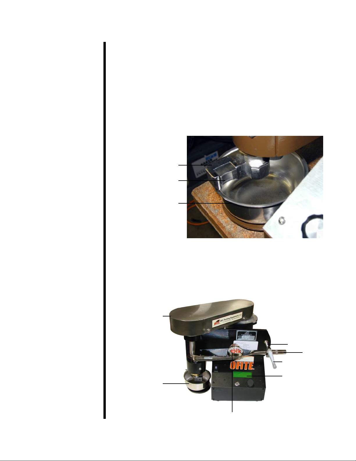
the wall of the bore hole. The OFITE combination EP (Extreme Pressure)
and Lubricity tester is a high-quality instrument used to measure the lubri-
cating quality of drilling fluids, provide data to evaluate the type and quanti-
ty of lubricating additives that may be required, and predict wear rates of
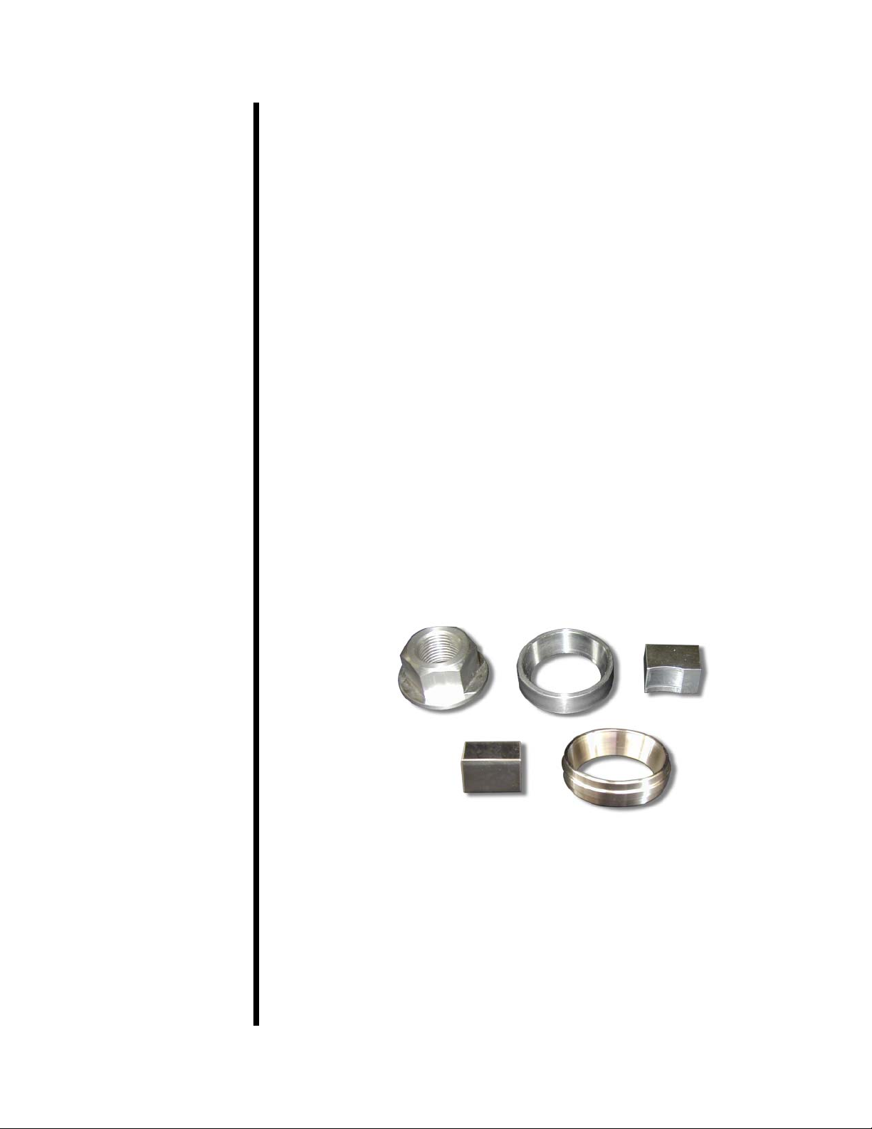
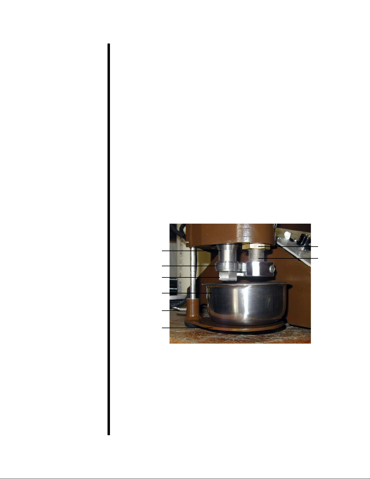
mechanical parts in known fluid systems. The test consists of measuring
the torque of a steel block while being pressed against a rotating steel ring.
The torque limit is 600 inch-pounds.
Lubricity (Surface to Surface Drag) Test
The more common lubricity test measures fluid resistance of various lubri-
cating additives. For the standard lubricity coefficient test, 150 inch-pounds
of force (the equivalent of 5,000 to 10,000 PSI (34,500 - 69,000 kPa) pres-
sure on the intermediate fluid) are applied between two hardened steel sur-
faces, a block, and a ring rotating at 60 RPM.
EP (Extreme Pressure) Test
This test produces an indication of the film strength of the fluid being tested
by applying a measured force to a torque-sensitive bearing cup with the
torque arm. The EP test is typically run at a high shear rate, 1,000 RPM,
with fluid pressures ranging from 5,000 to 10,000 PSI (34,500 - 69,000
kPa) between the steel surfaces.
- Belt-Driven Motor: ½ hp, 90 Volt DC, 5.5 Amps
- Maximum 600 inch-pounds of torque
- 1,000 RPM Maximum
- Size: 19" × 15" × 14" (48.3 × 38.1 × 35.6 cm)
- Weight: 56 lbs. (25.4 kg)
OFITE, 11302 Steeplecrest Dr., Houston, TX 77065 USA / Tel: 832-320-7300 / Fax: 713-880-9886 / www.ofite.com 2
Specifications
Description
Introduction

#111-02 Test Ring for Lubricity Test
#111-04 Test Block for EP Test
#111-06 Test Ring for EP Test
#111-08 Test Block for Lubricity Test
#111-09 Sample Cup
#111-10 Torque Wrench
#111-13 Fine Grinding Compount, Grit 280, 16 oz Can
#111-14 Coarse Grinding Compound, Grit 120, 16 oz Can
#111-16 3⁄4" Service Wrench
#111-17 11⁄4" Service Wrench
#111-18 15⁄16" Combination Wrench
#164-32 Male Connector for Power Cable (230 Volt Only)
#172-09 Fuse, 10 Amp
Optional:
#111-01 Padded Transport Case
#111-00-SP Spare Parts for #111-00:
#111-02 Test Ring for Lubricity Test; Qty: 6
#111-04 Test Block for EP Test; Qty: 6
#111-06 Test Ring for EP Test; Qty: 6
#111-08 Test Block for Lubricity Test; Qty: 6
#111-09 Sample Cup
#111-11 7x Measuring Magnifier with Inch Scale
#111-13 Fine Grinding Compount, Grit 280, 16 oz Can
#111-14 Coarse Grinding Compound, Grit 120, 16 oz Can
OFITE, 11302 Steeplecrest Dr., Houston, TX 77065 USA / Tel: 832-320-7300 / Fax: 713-880-9886 / www.ofite.com 3
Components
Top Row (Left to Right): Retainer Nut, Lubricity Test Ring, Lubricity Test Block
Bottom Row: EP Test Block (Left), EP Test Ring (Right)

Control
Panel
The instrument control panel consists of a display screen, a Scroll Wheel,
and an Exit button.
The Scroll Wheel spins clockwise and counter-clockwise. Spinning the
wheel scrolls through the menu and options. Pushing the Scroll Wheel in
signals acceptance.
The Exit button cancels any pending input and returns to the Main Menu.
Pushing the Exit button while on the Main Menu accesses the Zero Menu.
To access the Main Menu, push in the Scroll Wheel while on the home
screen. On the Main Menu you can set the motor speed to one of 5 preset
values:
1. Set RPM to 0
2. Set RPM to 60
3. Set RPM to 200
4. Set RPM to 600
5. Set RPM to 1000
To access the Manual Speed Select, spin the Scroll Wheel while on the
home screen. From here you can increase the motor speed by spinning
the wheel clockwise and decrease it by spinning it counter-clockwise.
By default, the speed increases by 1 RPM for each increment of wheel
spin. By pressing the wheel in, you can increase this increment to 10 or
100 RPM.
SPIN: ADJUST RPM
ENTER: ADJUST RPM BY 1, 10, 100
To access the Zero Menu, press the Exit button while on the home screen.
From here you can set the test time and torque values to zero.
1. Zero the Test Time
2. Set Torque = 0.0
3. Restore Last Torque
To stop the motor, press the Scroll Wheel in twice.
OFITE, 11302 Steeplecrest Dr., Houston, TX 77065 USA / Tel: 832-320-7300 / Fax: 713-880-9886 / www.ofite.com 4

Lubricity Test Refer to page 4 for instructions on using the control panel.
1. Clean the lubricity test ring (#111-02 with a flat outer surface) and the
lubricity test block (#111-08 with a concave groove on one side) with
Acetone and rinse them thoroughly with deionized water. All parts of
the machine in the sample area must be clean before starting a test.
Do not touch the metal contact areas with bare hands.
Removing the ring from the main shaft can change the alignment of the
contact area with the block. We recommend removing the ring only to
replace it or to switch between lubricity and extreme pressure tests.
2. Place the lubricity test ring squarely onto the tapered portion of the
main shaft. Using a 15⁄16" wrench, secure the test ring retainer nut.
Make sure the ring seats squarely on the taper of the shaft.
3. Turn on the power and let the machine run for approximately 15 min-
utes.
4. Place the lubricity test block in the block holder with the concave side
facing out and align it with the test ring.
5. Set the motor speed to 60 RPM.
6. After the unit has been running for 15 minutes, zero the torque reading
(refer to page 4 for instructions). Run the unit approximately 5 more
minutes and adjust again if required.
7. Fill the stainless steel sample cup with deionized water (260 - 280 mL)
and place it on the lowered cup stand. Raise the cup stand until the
test ring, test block, and block holder are fully submerged. Tighten the
thumbscrew to secure the cup stand.
OFITE, 11302 Steeplecrest Dr., Houston, TX 77065 USA / Tel: 832-320-7300 / Fax: 713-880-9886 / www.ofite.com 5
Sample Cup
Retainer Nut
Test Ring
Main Shaft
Thumb Screw
Cup Stand
Locking Nut
Torque
Bushing
Important
!
Note

8. Position the torque arm so that it fits inside the concave portion of the
torque arm clamp. Turn the torque adjust handle clockwise until the
torque gauge on the arm reads 150 inch-pounds.
Never apply torque to the test ring unless it is submerged in fluid.
9. Let the machine run for 5 minutes and then record the torque reading.
The torque reading should be 34 ± 2 (between 32 and 36). If the
torque reading is outside this range, see the "Standardizing the Test
Block" section on page 12. Otherwise, proceed to step 10.
10. Zero the torque reading. Then, lower the cup stand and discard the
fluid. Wipe any remaining fluid from the sample cup, block, block hold-
er, and test ring.
OFITE, 11302 Steeplecrest Dr., Houston, TX 77065 USA / Tel: 832-320-7300 / Fax: 713-880-9886 / www.ofite.com 6
Sample Cup
Test Block
Test Block Holder
Sample Cup
Belt Guard
Torque Gauge
Torque Arm
Display Screen
Torque Adjust Handle
Torque Arm Clamp
Important
!

11. Mix your test fluid (260 - 280 mL) for at least ten minutes. Pour the test
fluid into the stainless steel cup. Place the cup on the stand and raise
it until the block holder and test ring are fully immersed in the fluid.
Secure the stand in place with the thumbscrew.
12. Set the motor speed to 60 RPM, then zero the torque reading. Run the
machine for approximately 5 minutes and adjust again if necessary.
13. Turn the torque adjustment handle clockwise until 150 inch-pounds of
torque have been applied to the test block. Let the machine run for 3 to
5 minutes.
14. After 3 to 5 minutes, record the torque reading and release the
torque on the arm.
OFITE, 11302 Steeplecrest Dr., Houston, TX 77065 USA / Tel: 832-320-7300 / Fax: 713-880-9886 / www.ofite.com 7
Important
!

Before the test can be accurately run, the machine must be in proper
adjustment. To test for proper adjustment, or to run a standard test, pro-
ceed through the following steps.
Refer to page 4 for instructions on using the control panel.
1. Clean the EP test ring (#111-06 with a raised narrow surface) and the
EP test block (#111-04 cube with smooth surface) with Acetone and
rinse them thoroughly with deionized water. All parts of the machine in
the sample area must be clean before starting a test.
Do not touch metal contact areas with bare hands.
Removing the ring from the main shaft can change the alignment of the
contact area with the block. We recommend removing the ring only to
replace it or to switch between lubricity and extreme pressure tests.
2. Place the EP test ring squarely onto the tapered portion of the shaft.
Using a 15⁄16" wrench, secure the test ring retainer nut. Make sure the
ring seats squarely on the taper of the shaft.
3. Turn the power on. Let the unit run for 15 minutes.
4. Place the EP test block in the block holder.
5. Set the motor speed to 1000 RPM.
6. Zero the torque reading on the display (see page 4 for instructions).
7. Run the machine at 1,000 RPM for approximately 3 minutes, or until
the torque zero reading appears to stabilize and no longer drifts appre-
ciably. Zero the torque reading (see page 4).
8. Position the torque arm so that the arm fits inside the concave portion
of the torque arm clamp.
9. Fill the stainless steel sample cup with test fluid (260 - 280 mL) and
place it on the lowered cup stand. Raise the cup stand until the test
ring, test block, and block holder are submerged. Tighten the thumb-
screw to secure the cup stand.
10. Rotate the torque adjust handle clockwise so that the reading on the
torque wrench increases at a rate of no more than 5 inch-pounds per sec-
ond. Continue until the torque wrench reading reaches the desired load or
until a seizure occurs. If a seizure occurs, quickly record the readings on
the torque wrench and on the display screen, then remove the load.
Due to the extreme friction between the ring and the block, the
fluid will get very hot and may reach the boiling point.
OFITE, 11302 Steeplecrest Dr., Houston, TX 77065 USA / Tel: 832-320-7300 / Fax: 713-880-9886 / www.ofite.com 8
Important
!
EP Test
Important
!
Note

A seizure is defined as tearing and galling (scarring) of the metal to
metal contact between the test ring and the test block surface. This
represents a complete breakdown of the extreme pressure lubricating
ability of the fluid or mud under the test conditions. A seizure is identi-
fied by a rapid rise in the torque reading. It may also appear as a
sharp, substantial increase in current, which then drops back to normal.
This type of seizure usually occurs at a relatively low torque reading or
during tests of highly abrasive muds or muds containing a high solids
content. A seizure is also accompanied by an obvious change in the
pitch (sound) of the machine (a rasping sound). After a seizure, the
wear surface on the test block will be very large and will appear rough
and scarred.
11. Repeat steps 1 through 10 until a pass is obtained. A pass is identified
in one of two ways.
a. A five minute run at a constant load during which the torque meter
reading remains essentially constant and the wear surface is small
and polished.
b. A five minute run in which there is a moderate amount of torque
meter deflection and the wear surface is moderate, and may either
be polished or dull, depending upon the abrasiveness of the test
fluid.
12. After removing and cleaning the test block (see "Disassembly" below),
examine the test block for wear. With the aid of a magnifying glass
(part #111-11), observe the scar left on the block by the test ring. If the
scar is rectangular, the test block is properly aligned in the holder. Your
test is complete. If the scar is triangular or trapezoidal, the alignment is
off and must be corrected. Refer to the "Repositioning the Test Block"
section.
1. Record the lowest torque wrench reading (in inch-pounds) and the
average torque meter reading (display screen) at which the seizure
occurred.
2. Record the following at the conclusion of a pass or if a 5-minute test
does not produce a seizure.
a. Torque meter reading in inch-pounds.
b. Scar width in inches (refer to page 14).
c. Film strength in PSI. This value must be calculated. (refer to page 14)
d. Average current (torque reading on the display screen in pounds
divided by 10) in amps.
OFITE, 11302 Steeplecrest Dr., Houston, TX 77065 USA / Tel: 832-320-7300 / Fax: 713-880-9886 / www.ofite.com 9
EP Test
Reporting Test Results
Note

1. Turn the power off.
2. Lower the cup stand and turn the torque arm clamp up and away.
3. Swing the torque arm back to allow removal of the test block.
4. Remove and thoroughly rinse the test block with deionized water.
5. Remove the cup and discard the test fluid.
6. Remove the retaining nut and test ring.
7. Use Acetone, deionized water, and a brush to clean the entire test area,
including the test ring, test block, and block holder. To prevent rust,
ensure that the entire unit is clean and dry. If the machine is to be
stored for a long period of time, coat all components with oil.
1. The roller bearing in the main shaft may occasionally need to be
greased. If you notice a squeaking noise coming from the main shaft,
add a high-temperature bearing grease (such as Lubriplate No. 12601)
via the zerk fitting on the back of the unit.
2. The upper main shaft ball bearing is sealed and will need replacement
only when the shaft end-lay can be detected. Shaft end-lay is indicated
by excessive oscillation in the torque reading. To replace the bearing:
OFITE, 11302 Steeplecrest Dr., Houston, TX 77065 USA / Tel: 832-320-7300 / Fax: 713-880-9886 / www.ofite.com 10
Gear
Plate
Main Shaft
Maintenance
Disassembly

a. Remove the belt guard.
b. Remove the gear from the main shaft.
c. Unscrew the four screws beneath the gear and remove the plate to
reveal the bearing.
d. Press the bearing upward from underneath and slide it up and off
the main shaft.
e. Slide the new bearing down the main shaft and into place.
f. Re-install the plate and secure it tightly in place.
g. Re-install the gear, belt, and belt guard. Check the belt tension as
described below.
3. Keep the control panel clean and dry. Fluids on the panel can seep
around electrical components and cause damage.
4. Periodically remove the belt guard and check the belt tension. Ensure
sufficient tightness so that when the motor is stalled, the belt will not
slip. To increase the belt tension, loosen the motor mount bolts on the
back of the unit, slid the motor towards the torque adjust handle and
then retighten the mounting bolts. Re-install the belt guard.
OFITE, 11302 Steeplecrest Dr., Houston, TX 77065 USA / Tel: 832-320-7300 / Fax: 713-880-9886 / www.ofite.com 11

Maintenance
Standardizing the Test
Block
If the Coefficient of Friction of deionized water is not in the 32 to 36 range,
the ring and block surfaces must be reconditioned or standardized. In
order to standardize the block, a substantial portion (at least ½) of its
curved surface must be worn to a shiny condition with a minimum of
groove lines throughout this polished area.
Refer to page 4 for instructions on using the control panel.
1. Using a black marker, color the contact area of the test block. Install
the test block.
2. Turn the unit on and set the motor speed to 200 RPM.
3. Turn the torque wrench to bring the block into contact with the ring and
apply about 150 lbs. of pressure for 10 seconds.
4. Release pressure and reduce the motor speed to 0 RPM.
5. Remove the block and inspect the contact area. The markings left by
the ring should be centered top to bottom and left to right in the contact
area.
6. If the markings are not centered, complete the appropriate Block
Adjustment Procedure (page 13).
7. Repeat Steps 1 through 6 until the markings are centered.
8. Fill the sample cup about ¾ full with de-ionized water.
9. Cover the surface of the ring and the contact area of the block with
coarse grinding compound (part #111-14).
10. Turn the torque wrench to bring the block into contact with the ring.
11. Place the sample cup onto the cup pedestal and raise it to submerge
the ring and block.
12. Set the motor speed to 100 RPM and the pressure to 150 lbs. Run the
unit at these settings for six hours, changing the water and grinding
compound every two hours.
13. After six hours, switch to the fine grinding compound (part #111-13).
Increase the speed to 120 RPM and reduce the pressure to 75 lbs and
run the unit for another four hours. Change the water and grinding
compound every hour.
14. The complete burn-in process should take 10 hours. Clean the block
and ring with acetone to remove all of the grinding compound.
15. Return to step 9 of the Lubricity Test (page 6) and continue.
OFITE, 11302 Steeplecrest Dr., Houston, TX 77065 USA / Tel: 832-320-7300 / Fax: 713-880-9886 / www.ofite.com 12

Maintenance
Block Adjustment
The test block can be adjusted horizontally (left to right) or vertically (up
and down).
To adjust the block from left to right:
1. Loosen the socket head bolt located in the housing.
2. Using the supplied wrench turn the torque bushing. This will move
the shaft either left or right depending on the shaft position inside
the housing.
3. Tighten the socket head bolt in the housing.
To adjust the block up and down:
1. Loosen the socket head bolt in the housing.
2. Loosen the lock nut located on the torque bushing.
3. Center the block against the ring and adjust the lock nut (up or
down) so the lock nut is in contact with the housing while the block
is centered on the ring.
4. Tighten the socket head bolt to hold the adjustment.
5. Tighten the lock nut against the housing.
OFITE, 11302 Steeplecrest Dr., Houston, TX 77065 USA / Tel: 832-320-7300 / Fax: 713-880-9886 / www.ofite.com 13

Measurements
/ Calculations
Follow these steps to calculate the Film Strength of the test fluid:
A. To measure the scar length on the block, use a magnifier (part
#111-11) calibrated to read 0.005" (0.0127 cm). Place the magnifier
at the center of the scar parallel to the edges. This will allow you to
obtain the average width of the scar. Record the scar measurement
in inches.
B. To calculate the pressure on the block:
1. Begin by computing the total area of the scar on the block.
Multiply the width of the scar (in inches) by the length (in inches).
If you are measuring a trapezoidal scar, use the average width.
2. Calculate the force acting on the scar area by dividing the
torque meter reading (in inch pounds) at which a pass was
obtained by 1.5 in (the travel distance of the arm).
3. Calculate the pressure on the test block at the time the test was
stopped by dividing the force (2) by the scar area (1). This
pressure is the film strength of the mud. In equation form it is
written as follows:
P =
Where:
P = Film Strength (PSI)
T = Torque Meter Reading (in-lbs)
W = Scar Width (in)
L = Scar Length (in)
C. The Coefficient of Friction value for Deionized Water would be a
constant if the metallurgical structures of all rings and test blocks
were the same. At 60 RPM and 150 inch-pounds of load, the
torque meter reading should be 34. However, since every ring and
test block are different, a correction factor is required to achieve
accurate results. To calculate the correction factor, divide the stan-
dard meter reading for water (34) by the actual meter reading,
which you recorded in step 8 of the Lubricity Test (Page 6).
OFITE, 11302 Steeplecrest Dr., Houston, TX 77065 USA / Tel: 832-320-7300 / Fax: 713-880-9886 / www.ofite.com 14
T (in-lbs)
1.5 (in) × L (in) × W (in)

Correction Factor =
Mud Lubricity Coefficient = × Correction Factor
Percent (%) Torque Reduction at a Given Load = × 100
Where:
AL= Torque reading of untreated mud under force equal to BL
BL= Torque reading of treated mud under force equal to AL
Coefficient of Friction = =
Where:
F = The frictional force required to slide the block and ring surfaces
across each other at a given rate and is measured by the num-
ber of amperes required to turn the test ring at a prescribed
number of revolutions per minute.
W = The load or force with which the test block is pressed against
the test ring through the torque arm.
OFITE, 11302 Steeplecrest Dr., Houston, TX 77065 USA / Tel: 832-320-7300 / Fax: 713-880-9886 / www.ofite.com 15
F
W
Meter Reading
100
Meter Reading
100
Standard Meter Reading for Water
Actual Meter Reading for Water
AL- BL
AL
Other manuals for 112-00
1
This manual suits for next models
1
Table of contents
Other OfiTE Test Equipment manuals