OHAUS MB45 User manual

Ohaus Corporation
29 Hanover Road
Florham Park, NJ
07932-0900
Instruction Manual
MB45 Moisture Analyzer
On/Off
Test Menu
Display
Setup Enter Print
TARE
START/STOP
MB45

Ohaus Corporation, 29 Hanover Road, Florham Park, New Jersey, 07932, USA
Declaration of Conformity We, Ohaus Corporation, declare under our sole responsibility that the balance models listed below
marked with “CE” - are in conformity with the directives and standards mentioned.
Konformitätserkärung Wir, die Ohaus Corporation, erklären in alleiniger Verantwortung, dass die untenstehenden
Waagentypen, gekennzeichnet mit “CE” - mit den genannten Richtlinien und Normen übereinstimmen.
Déclaration de conformité Nous, Ohaus Corporation, déclarons sous notre seule responsabilité, que les types de balance ci-
dessous cité - munis de la mention «CE» - sont conformes aux directives et aux normes mentionnées ci-après.
Declaración de Conformidad Nosotros, Ohaus Corporation, declaramos bajo responsabilidad exclusiva que los modelos de
balanzas indicados a continuación - con el distintivo ,CE’ - están conformes con las directivas y normas citadas.
Dichiarazione di conformità Noi, Ohaus Corporation, U.S.A, dichiariamo sotto nostra unica responsabilità, che i tipi di bilance
specificati di seguito - contrassegnati con la marcatura “CE” - sono conformi alle direttive e norme citate.
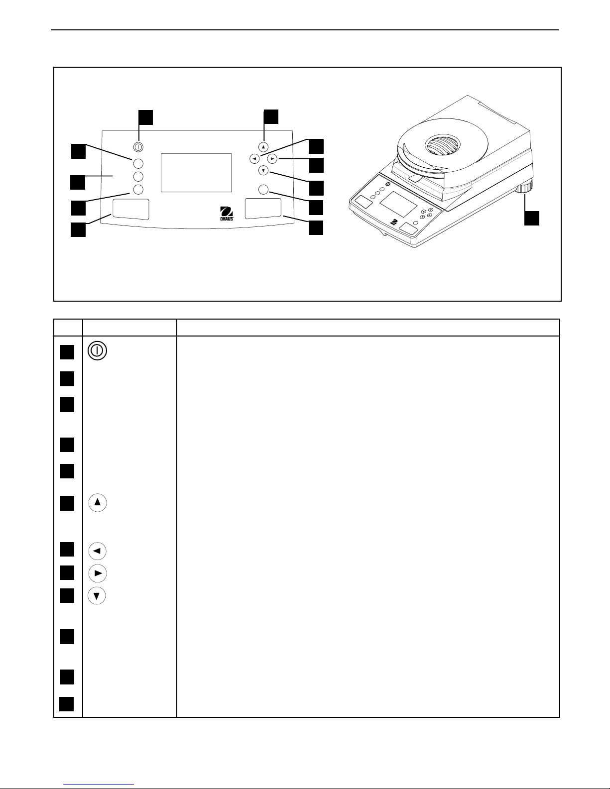
Balance Type/Waagentyp/Type de balance/Tipo de balanza/Tipo di bilancia Moisture Analyzer MB45
Marked with: Directive Standard
gekennzeichnet mit: Richtlinie Norm
munis de la mention: Directive Norme
con el distintivo: Directiva Norma
contrassegnati con la Direttiva Norma
marcatura:
EU 73/23/EEC Low Voltage EN61010-1:1993 + A2: 1995 Safety Regulations
EU 73/23/EEC Niederspannung EN61010-1:1993 + A2: 1995 Sicherheitsbestimmungen
EU 73/23/EEC Basse tension EN61010-1:1993 + A2: 1995 Consignes de sécurité
EU 73/23/EEC Baja tensión EN61010-1:1993 + A2: 1995 Disposiciones sobreseguridad
EU 73/23/EECBassatensione
EN61010-1:1993 + A2: 1995 Prescrizioni di sicurezza
EU 89/336/EEC EN55011: 1991 (class B) Emissions; EN61000-3-2
Electromagnetic compatibility EN50082-2:1995 Immunity; EN61000-3-3
EU 89/336/EEC EN55011: 1991 (class B) Funkstörungen; EN61000-3-2
elektromagnetische Verträglichkeit EN50082-2:1995 Immunität; EN61000-3-3
EU 89/336/EEC EN55011: 1991 (class B) Emissions parasites; EN61000-3-2
Compatibilité électromagnétique EN50082-2:1995 Immunité; EN61000-3-3
EU 89/336/EEC EN55011: 1991 (class B) Radiointerferencias; EN61000-3-2
Compatibilidad electromagnética EN50082-2:1995 Inmunidad; EN61000-3-3
EU 89/336/EEC EN55011: 1991 (class B) Radiointerferenze; EN61000-3-2
Compatibilità elettromagnetica EN50082-2:1995 Immunità; EN61000-3-3
ISO9001RegistrationforOhausCorporation.
OhausCorporation,USA,wasexaminedandevaluatedin1994bytheBureauVeritasQualityInternational,BVQI,
andwas awardedISO9001 registration. This certifiesthatOhaus Corporation,USA,has aqualitysystemthatconforms withthe internationalstandardsforquality
managementandqualityassurance(ISO9000series). RepeatauditsarecarriedoutbyBVQIatintervalstocheckthatthequalitysystemisoperatedinthepropermanner.
ISO9001-ZertifikatfürOhausCorporation.
DieFirmaOhausCorporation,USA,wurde1994durchdasBureauVeritasQualityInternationalBVQIgeprüft,underhielt
dasISO9001Zertifikat. Diesesbescheinigt,dassOhausCorporation,USAübereinQualitätssystemverfügt,welchesdeninternationalenNormenfürQualitätsmanagement
undQualitátssicherung(ISO9000er-Reihe)entspricht. AnlässlichvonWiederhol-AuditsdurchdasBVQIwirdperiodischüberprüft,obdasQualitätssystemzweckmässig
gehandhabtwird.
CertificatISO9000pourOhausCorporation.
LasociétéOhausCorporation,USA,aétécontrôléeen1994parBureauVeritasQualityInternationalBVQIetaobtenu
lecertificat,degréISO9001. Celui-ciattestequeOhausCorporation,USA,disposed’unsystèmequalitécorrespondantauxnormesinternationalespourlagestiondela
qualitéetpourI’assurancequalité(degréISO9000). DesauditsrégulierseffectuésparlaBVQIvérifientsilesystèmequalitéestappliquédefaconappropriée.
CertificadoISO9001paraOhausCorporation.
LafirmaOhausCorporation,USA,hasidoinspeccionadaporlaBureauVeritasQualityInternational(BVQI)yha
obtenidoelcertificadoISO9001. EstoacreditaqueOhausCorporation,USA,disponedeunsistemadecalidadquecumplelasnormasinternacionalesparagestiónygarantfa
decalidad(ISOserie9000). ConocasióndelasinspeccionesderepetibilidadporpartedelaBVQI,secompruebaperiódicamentesielsistemadecalidadsemanipulade
formacorrecta.
CertificatoISO9001perla OhausCorporation.
llsistemadigaranziadellaqualitàdellaSocietàOhausCorporation,USAècertificatoISO9001sindal1994dal
BureauVeritasQualityInternationalBVQI,ecosìfomisceladimostrazionecheilsuosistemadiGaranziaQualitàsoddisfaimassimirequisiti.VerificheperiodichedelBVQI
garantisconoche ilsistemaqualit
àopera correttamente.

NOTE:THIS EQUIPMENT HAS BEEN TESTED AND FOUND TO COMPLY WITH THE LIMITS FOR A CLASS A
DIGITAL DEVICE, PURSUANT TO PART 15 OF THE FCC RULES.
THESE LIMITS ARE DESIGNED TO PROVIDE REASONABLE PROTECTION AGAINST HARMFUL INTERFER-
ENCE WHEN THE EQUIPMENT IS OPERATED IN A COMMERCIAL ENVIRONMENT. THIS EQUIPMENT
GENERATES, USES, AND CAN RADIATE RADIO FREQUENCY ENERGY AND, IF NOT INSTALLED AND USED
IN ACCORDANCE WITH THE INSTRUCTION MANUAL, MAY CAUSE HARMFUL INTERFERENCE TO RADIO
COMMUNICATIONS. OPERATION OF THIS EQUIPMENT IN A RESIDENTIAL AREA IS LIKELY TO CAUSE
HARMFUL INTERFERENCE IN WHICH CASE THE USER WILL BE REQUIRED TO CORRECT THE INTERFER-
ENCE AT HIS OWN EXPENSE.
THIS DIGITAL APPARATUS DOES NOT EXCEED THE CLASS A LIMITS FOR RADIO NOISE EMISSIONS FROM
DIGITAL APPARATUS AS SET OUT IN THE INTERFERENCE-CAUSING EQUIPMENT STANDARD ENTITLED
DIGITAL APPARATUS, ICES-003 OF THE DEPARTMENT OF COMMUNICATIONS.
CET APPAREIL NUMERIQUE RESPECTE LES LIMITES DE BRUITS RADIOELECTRIQUES APPLICABLES AUX
APPAREILS NUMERIQUES DE CLASSE A PRESCRITES DANS LA NORME SUR LE MATERIEL BROUILLEUR :
APPAREILS NUMERIQUES, NMB-003 EDICTEE PAR LE MINISTRE DES COMMUNICATIONS.
Unauthorized changes or modifications to this equipment are not permitted.
NOTICE:
This manual was prepared by:
George W. Smidhum - Technical Writer
Steve Nickerson - Software Engineer
Neil Olesen - Project Engineer

4
Contents
OVERVIEW OF CONTROLS .................................................................................................................. 7
1. GETTING TO KNOW YOUR MOISTURE ANALYZER ................................................................................. 8
1.1 Introduction ...................................................................................................................................... 8
1.2 Overview of the Moisture Analyzer ....................................................................................................... 8
1.3 What is a Moisture Analyzer ?............................................................................................................. 8
1.4 Safety is first ................................................................................................................................... 10
1.5 What you should know about these instructions ................................................................................. 12
2. INSTALLATION ................................................................................................................................13
2.1 Unpacking and checking the standard equipment ............................................................................... 13
2.2 Selecting the location ....................................................................................................................... 14
2.3 Installing the heat shield, draft shield and sample pan holder ...............................................................14
2.4 Leveling the Moisture Analyzer .......................................................................................................... 15
2.5 Connecting to a power supply........................................................................................................... 15
2.6 Switching the Moisture Analyzer on or off ........................................................................................... 16
3. MAKING A SIMPLE MEASUREMENT ................................................................................................ 17
4. THE MENUs .................................................................................................................................... 21
4.1 What are the menus?....................................................................................................................... 21
4.2 Menu operation ............................................................................................................................... 22
5. ANALYZER SETUP ........................................................................................................................... 24
5.1 Lockout .......................................................................................................................................... 24
5.2 Weight calibration ........................................................................................................................... 25
5.3 Temperature calibration.................................................................................................................... 26
5.4 Language setting............................................................................................................................. 27
5.5 Audible signal level.......................................................................................................................... 27
5.6 Time and date setting ...................................................................................................................... 27
5.7 RS232 settings ............................................................................................................................... 29
5.8 Setting print and GLP printing on or off............................................................................................... 31
5.9 Adjusting display contrast and brightness .......................................................................................... 32
5.10 Factory reset ................................................................................................................................... 33
Contents

5
Contents
6. OPERATING YOUR MOISTURE ANALYZER .......................................................................................... 34
6.1 The operating concept...................................................................................................................... 34
6.2 Entering test ID................................................................................................................................ 34
6.3 Setting the drying profile ................................................................................................................... 35
6.4 Setting the drying temperature ........................................................................................................... 37
6.5 Selecting the switch-off criterion ........................................................................................................ 38
6.6 Result ............................................................................................................................................ 40
6.7 Custom units .................................................................................................................................. 40
6.8 Target weight .................................................................................................................................. 43
6.9 Print interval ................................................................................................................................... 43
6.10 Saving test setup ............................................................................................................................. 44
6.11 Running test setup........................................................................................................................... 44
6.12 Displaying data during run mode ...................................................................................................... 46
6.13 Exiting test setup and not saving changes .......................................................................................... 47
7. USING THE LIBRARY ....................................................................................................................... 48
8. HOW TO OBTAIN THE BEST RESULTS ............................................................................................... 49
8.1 Measurement principle of the Halogen Moisture Analyzer ..................................................................... 49
8.2 Sampling and sample preparation..................................................................................................... 50
8.3 Selection of the drying temperature .................................................................................................... 53
8.4 Selection of the drying program......................................................................................................... 54
8.5 Selection of the drying time............................................................................................................... 56
8.6 Analysis of the drying profile ............................................................................................................. 57
9. PRINTING TEST DATA ...................................................................................................................... 58
9.1 RS232 command table .................................................................................................................... 60
9.2 RS232 Pin out ................................................................................................................................ 60
10. CARE AND MAINTENANCE ............................................................................................................... 61
10.1 Cleaning interior/exterior components ................................................................................................ 61
10.2 Replacing power line fuse ................................................................................................................ 63
10.3 Troubleshooting .............................................................................................................................. 64
10.4 Error detection ................................................................................................................................. 65
10.5 Service information .......................................................................................................................... 65

6
Contents
10.6 Accessories .................................................................................................................................... 65
10.7 Specifications.................................................................................................................................. 66
A1 APPENDIX - APPLICATION EXAMPLES.............................................................................................. 67

Overview of controls
7
On/Off
Test Menu
Display
Setup Enter Print
TARE
START/STOP
MB45
Overview of controls
4
2
5
10
3
12
7
9
8
6
11
No. Designation Function
1 Turns ON/OFF display and fan. ON returns with last screen. (All modes)
2 Test Menu button When pressed, selects Test Library screen.
3 Display button When pressed, will return to the current test or cycles through several display
screens (run mode).
4Setup button When pressed, brings up analyzer setup menu.
5
5 Start/Stop button When pressed, either starts or stops drying process.
6button When pressed, travels up through menu options and selects alphanumeric
characters.
7button When pressed, travels to the left through displays.
8 button When pressed, travels to the right through displays.
9 button When pressed, travels down through menu options and selects alphanumeric
characters.
110 Enter/Print button When pressed, accepts selection/input (select mode) or sends print command
during a test (run mode).
11 Tare button When pressed, performs a tare function. Pressing during a test has no effect.
12 Leveling feet Used to level the Moisture Analyzer.
1
On/Off
Test Menu
Display
Setup Enter Print
TARE
START/STOP
MB45
11

8
Getting to know your Moisture Analyzer - Section 1
1. Getting to know your Moisture Analyzer
This section provides you with essential information on your MB45 Moisture Analyzer. Please read through the
section carefully even if you have previous experience with OHAUS Moisture Analyzers and be sure to familiarize
yourself with the safety notes.
1.1 Introduction
Thank you for deciding to purchase a MB45 Halogen Moisture Analyzer from Ohaus. Behind your instrument
stands OHAUS, a leading manufacturer of precision Moisture Analyzers, Balances, Scales and Indicators. An
Aftermarket Department with trained instrument technicians is dedicated to provide you with the fastest service
possible in the event your instrument requires servicing. OHAUS also has a Customer Service Department to
answer any inquiries regarding applications and accessories.
To ensure you make full use of the possibilities offered by your Moisture Analyzer, please read the manual
completely before installation and operation.
1.2 Overview of the Moisture Analyzer
The Moisture Analyzer offers a high level of operating convenience and useful functions to make accurate
measurements.
The Moisture Analyzer has the following features:
Up to twice as fast as IR Moisture Analyzers.
Fully programmable with front panel controls.
Extremely rugged and chemically resistant construction.
Ergonomic operating controls and a large, easily readable display.
Easy to follow menus for simplified operation.
Built-in functions for manual, automatic timing, printing intervals, and custom units.
Built-in selectable drying profiles.
Able to set step heating levels to accommodate a variety of sample types.
Built-in library stores up to 50 samples complete with setup parameters.
Built-in RS232 communication interface.
Any of five languages (English, French, Spanish, German, Italian) are selectable on the display.
Display contains all test data during drying process.
A variety of accessories includes disposable pan liners, calibration mass, temperature calibration kit,
interface communication cables, printer, and a security device.
1.3 What is a Moisture Analyzer?
The Ohaus Halogen Moisture Analyzer can be used to determine the moisture content of practically any sub-
stance. The instrument operates on the thermogravimetric principle: At the start of the measurement, the Mois-
ture Analyzer determines the weight of the sample; the sample is then quickly heated by the integral halogen
dryer unit and moisture vaporizes. During the drying operation, the instrument continuously determines the
weight of the sample and displays the result. On completion of drying, result is displayed as % moisture con-
tent, % solids, weight or % regain.

9
Section 1 - Getting to know your Moisture Analyzer
Of particular importance in practice is the rate of heating. In comparison with conventional infrared heating or
the drying oven method, for example, the halogen dryer of your instrument needs a shorter time to reach its
maximum heating power. It also allows the use of high temperatures; an additional factor in shortening the
drying time. Response times for the control of production are shorter resulting in increased productivity.
All parameters of a measurement (drying temperature, drying time, etc.) can be pre-selected. The Moisture
Analyzer offers many other possibilities. A few of these are listed here:
The integrated database for drying procedures stores the settings for your samples.
The drying characteristics can be matched to the type of sample.
You can choose between various types of result displays at any time.
Your settings and measurement results can be recorded and stored.
Built-in battery backup stores valuable data during a power failure.
Even though the Moisture Analyzer contains many functions, operation remains simple. The three button
controls on the front panel: Test Menu, Display and Setup allows entry into a variety of displays which includes
a test library where previous samples are recorded along with the test parameters so that a similar sample can
be run without the need to enter all new data. There are additional displays which indicate the test ID number,
selected temperature, actual temperature, time, initial weight and moisture content in percent, solids in percent,
grams or custom unit, % regain and a graphical display which illustrates the time and percentage.
Your Moisture Analyzer conforms with all common standards and directives. It supports standard procedures,
work techniques and records as required by GLP (Good Laboratory Practices) and SOP (Standard Operating
Procedure). We recommend the use of the OHAUS AS-142 Printer. Your Moisture Analyzer has a CE declaration
of conformity and OHAUS is registered to ISO 9001 - Quality Management System.

10
Getting to know your Moisture Analyzer - Section 1
Your Moisture Analyzer employs state of the art technology and meets the latest de-
mands regarding instrument safety. Improper operation can endanger personnel and
can cause property damage. For safe and dependable operation, please comply with
the following instructions:
The Moisture Analyzer is used for determination of the moisture in samples. Please
use the instrument exclusively for this purpose. Any other type of use can endanger
personnel and damage the instrument or other property.
The Moisture Analyzer must not be operated in a hazardous environment and only
under ambient conditions specified in these instructions.
The Moisture Analyzer may be operated only by trained personnel who are familiar
with the properties of the samples used and with the handling of the instrument.
Your Moisture Analyzer is supplied with a 3-pin power cable with an equipment
grounding conductor. Only extension cables which meet the relevant standards and
also have an equipment grounding conductor may be used. Intentional disconnec-
tion of the equipment grounding conductor is prohibited.
1.4 Safety is first
The Halogen Moisture Analyzer works with heat!
Ensure sufficient free space around the instrument to avoid heat accumulation and
overheating (approximately 1 m free space above the instrument).
Never place flammable materials on, below or next to the instrument as the area
around the dryer unit warms up.
Exercise caution when removing the sample. The sample itself, the sample cham-
ber and any sample containers may still be very hot.
During operation, you should never open the dryer unit as the ring-shaped heating
element or its protective glass can reach 400°C! If you have to open the dryer unit on
occasion, disconnect the instrument from the power supply and wait until the dryer
unit has cooled down completely.

11
Section 1 - Getting to know your Moisture Analyzer
Certain samples require special care!
With certain types of samples, there is a possibility of danger to personnel or damage to
property through:
Fire or explosion:
Flammable or explosive substances;
Substances containing solvents;
Substances which release flammable or explosive vapors when heated.
With such samples, work at a drying temperature that is low enough to prevent the
formation of flames or an explosion and wear protective goggles. Should there be
any uncertainty regarding the flammability of a sample, always work with a small
sample (maximum. 1 gram). In such cases, never leave the instrument unat-
tended! In cases of doubt, perform a careful risk analysis.
Poisoning, burning:
Substances which contain toxic or caustic components. Such substances may be
dried only in a fume hood.
Corrosion:
Substances which release corrosive vapors when heated (e.g. acids). In the case
of such substances, we advise you to work with small amounts of samples as the
vapor can condense on cooler housing parts and cause corrosion.
Please note that the user always takes responsibility and assumes liability for
damage caused by use of the types of samples mentioned above!
Never make any modifications or constructional alterations to the instrument and
use only original spare parts and optional equipment from Ohaus Corporation.
Your Moisture Analyzer is a rugged, precision instrument but you should still treat it
carefully; it will then provide you with many years of trouble-free operation.
Please comply with all notes and instructions in these operating instructions. Keep
the instructions in a safe place where they are immediately at hand if any points are
unclear. If you lose these instructions, please contact your OHAUS dealer for an
immediate replacement.

12
Getting to know your Moisture Analyzer - Section 1
1.5 What you should know about these instructions
These instructions guide you step by step through the operation of your Moisture Analyzer. Section 2 provides
detailed installation instructions. Section 3 allows you to perform a simple measurement. Section 4 explains
the menu operation. Section 5 explains how to set the analyzer up. Section 6 covers the configuring and
operation of the analyzer. Section 7 explains the use of the built-in library. Section 8 explains how to obtain the
best results. Section 9 details printing operations. Section 10 covers maintenance. A1 is an appendix with
application samples.
The following graphic orientation aids represent certain functions, notices and controls. These graphic aids are
not meant to be step by step operational procedures but simply a guide.
This hand symbol indicates pressing a button.
This representation symbolizes the current display of your Moisture
Analyzer.
This symbol indicates safety and hazard instructions which must be
complied with. Nonconformance with such instructions can lead to
personal injuries to the user, damage to the Moisture Analyzer or other
tangible assets or to malfunctions.
This symbol indicates additional information and instructions which
facilitate your handling of the Moisture Analyzer and contribute to proper
and economical use.

13
Section 2 - Installation
2. Installation
In this section, you will learn how you unpack and install your new Moisture Analyzer and prepare it for opera-
tion. On completion of the steps described in this section, your Moisture Analyzer is ready for operation.
2.1 Unpacking and checking the standard equipment
Open the package and remove the instrument and the accessories. Check the completeness of the delivery.
The following accessories are part of the standard equipment of your new Moisture Analyzer.
1 Box, Aluminum sample pans
1 Pan support
1 Pan handler
1 Specimen sample (circular, absorbent cellulose disk)
1 Draft shield element
1 Heat shield
1 Power cable
1 Set of operating instructions
1 Warranty card
Remove packing material from the instrument.
Check the instrument for transport damage. Immediately inform your Ohaus dealer if you have complaints or
parts are missing.
Store all parts of the packaging. This packaging guarantees the best possible protection for the transport of your
instrument.

14
Installation - Section 2
2.2 Selecting the location
The Moisture Analyzer should always be used in an environment which is free from excessive air currents, corro-
sives, vibration, and temperature or humidity extremes. These factors will affect displayed weight readings.
DO NOT install the Moisture Analyzer:
Next to open windows or doors causing drafts or
rapid temperature changes.
Near air conditioning or heat vents.
Near vibrating, rotating or reciprocating equipment.
Near magnetic fields or equipment that generate
magnetic fields.
On an unlevel work surface.
In confined areas, allow sufficient space around the
instrument for ease of operation and keep away from
radiating heat sources.
On/Off
TestMenu
Display
Setup Enter Print
TARE
START/STOP
MB45
On/Off
TestMenu
Display
Setup Enter Print
TARE
START/STOP
MB45
On/Off
TestMenu
Display
Setup Enter Print
TARE
START/STOP
MB45
Lift the cover straight up and Install the heat shield in the base of the
heating chamber.
Install the draft shield element (only one position possible) on top of the
heat shield.
Install the pan support into postion. Turn the pan support until it en-
gages. In the locked position, the rear arm of the pan support points
directly towards the rear of the analyzer.
2.3 Installing the heat shield, draft shield and sample pan holder
PAN SUPPORT
DRAFT SHIELD
HEAT SHIELD

15
Section 2 - Installation
2.5 Connecting to a power supply
Check to ensure the voltage identification label on the Moisture Analyzer
matches your local line voltage. If this is not the case, do not connect the
Moisture Analyzer to the power supply, contact your responsible OHAUS
dealer.
The halogen dryer unit is designed to operate at a specific line voltage
(120 V ac or 240 V ac). The dryer unit is installed at the factory and is
matched to the particular line voltage of the country of destination.
Connection to a line voltage that is too high can lead to burning out the
halogen heater, whereas, a supply voltage that is too low will prolong the
drying process and the instrument may not operate properly.
2.4 Leveling the Moisture Analyzer
Exact horizontal positioning and stable installation are prerequisites for repeatable results. To compensate for
small irregularities or inclinations at the location, the instrument can be leveled.
Adjust the leveling feet at the rear of the Moisture Anlyzer until the air
bubble in the indicator is centered. The level indicator is located under
the cover towards the rear of the Moisture Analyzer.
NOTE: The instrument should be leveled each time its location is
changed.
Leveling
Foot
Leveling
Indicator

16
Installation - Section 2
Connect the power cord supplied to the three pin connector located at the
rear of the Moisture Analyzer and to a power source. The Moisture
Analyzer becomes operational as soon as power is applied. The display
will remain off until the On/Off button is pressed.
WARNING:
If the power cable supplied is not long enough, use only a 3-pin exten-
sion cable with equipment grounding connector.
Allow the Moisture Analyzer to warm up for at least 30 minutes to
enable it to adapt itself to the ambient conditions. If the Moisture Analyzer
has been stored in a very cold environment before installation, it may
require several hours for it to stabilize.
2.6 Switching the Moisture Analyzer on and off
Your Moisture Analyzer is on at all times when connected to a power source. The display can be turned on or
off.
To switch the Moisture Analyzer on, press the On/Off button. An internal
diagnostic test is performed; the display lights and the logo and product
name appears followed by the initial display.
To switch the Moisture Analyzer off, press the On/Off button. After the
analyzer has been switched off, it is in the standby mode. If you wish to
perform a test, press the On/Off button again.
As your Moisture Analyzer needs no warm-up time when in the standby
mode and is immediately ready for testing samples, we advise you to
switch the display off by use of the On/Off button and not to disconnect it
from the power supply. This also ensures that the Moisture Analyzer is
always in thermal equilibrium.
On/Off CLEAR
PAN
PRESS
TARE
TEST ID: -DEFAULT-
TEMP/TIME: 100C / 10:00
TARGET WT: 5 GRAMS
0.000
* GRAMS

17
Section 3 - Making a simple measurement
3. Making a simple measurement
With your Moisture Analyzer powered on, you are ready to operate for the first time and perform a simple mea-
surement. For this simple test, you will enter the Test Menu and enable the test. By doing this test, you will
become familiar with the instrument and the various displays.
Included with your Moisture Analyzer is a specimen sample for your first measurement. This sample is an
absorbent glass fiber pad. During your first measurement, the instrument operates with the factory settings.
If the display is not visible and the unit is plugged into a power source,
press the On/Off button.
The display indicates the parameters for DEFAULT settings. Follow the
instructions on the lower left side of the display.
NOTE: If the unit has been operated, the default test settings may have
changed. If required, see Section 6 to reset the test parameters.
On/Off
TEST ID: -DEFAULT-
TEMP / TIME: 100°C / 10:00
TARGET WT: 1 GRAMS
0.000
GRAMS
CLEAR
PAN,
PRESS
TARE
For this simple test, the default settings are:
Drying temperature is set to: 100°C
Profile is set to: standard
Switch Off is set to: timed 10:00 minutes
Display is set to: % moist
Print interval is set to: OFF
Target weight is set to: 1 grams
Save is set to: NO
Open the cover on the Moisture Analyzer.
Clear the pan.
*
Place the empty sample pan in the pan handler (this is possible without
tilting the sample pan if you insert this in the pan handler from the side
directly below the round flange). Place the pan handler in the sample
chamber. Ensure that the tongue of the pan handler fits exactly in the slot
of the draft shield element. The sample pan must lie flat in the pan
handler.
Note: It is advisable for you to work with the pan handler at all times. The
pan handler is ergonomic, safe and provides protection against possible
burns due to a hot sample pan.

18
Making a simple measurement - Section 3
Place the specimen sample in the sample pan (glass fiber pad).
TEST ID: -DEFAULT-
TEMP / TIME: 100°C / 10:00
INITIAL WT: 0.930 G
0.930
* GRAMS
ADD
SAMPLE
CLOSE
COVER
Wet the specimen sample with a 0.5 to 1 gram of water.
NOTE: Minimum sample size must be greater than 0.5 gram.
Close the cover.
START/STOP
Starting the test
Press the Start/Stop button. The Moisture Analyzer starts the drying and
measurement process.
Press the Tare button. This sets the Moisture Analyzer to zero. A new
display now appears with instructions.
TARE

19
Section 3 - Making a simple measurement
Observing the test progress
There are five displays available when the Moisture Analyzer is running a test. The Display button on the front
panel when pressed repeatedly accesses each of the five displays during the run mode of the Analyzer and
cycles though each display in the order shown below.
The displays indicate the Test ID, Temperature/Time, Initial Weight, actual temperature, elapsed time duration of
the test, either moisture, solids, grams, percent regain or a graph representing the actual test progress.
Press the Display button repeatedly to view the progress of the sample test with different displays.
The test automatically stops at the end of 10:00 minutes. If you want to end the test sooner, press the START/
STOP button.
TEST ID: -DEFAULT-
TEMP / TIME: 100°C / 10:00
INITIAL WT: 0.930 G
70°C
0:20 4.04%
MOISTURE
Drying and measurement
You are now able to follow the progress of the drying cycle on the dis-
play. This first display comes up automatically when the test was started.
TEST ID: -DEFAULT-
TEMP / TIME: 100°C / 10:00
INITIAL WT: 0.930 G
TEST ID: -DEFAULT-
TEMP / TIME: 100°C / 10:00
INITIAL WT: 0.930 G
TEST ID: -DEFAULT-
TEMP / TIME: 100°C / 10:00
INITIAL WT: 0.930 G
TEST ID: -DEFAULT-
TEMP / TIME: 100°C / 10:00
INITIAL WT: 0.930 G
8:11 8:11
8:11
8:11
100.00
%MOISTURE 0.00
%SOLIDS
0.000
GRAMS
1000.00
% REGAIN
*
8:11 0.000G 100.00%
***
TEST ID: -DEFAULT-
TEMP / TIME: 100°C / 10:00
INITIAL WT: 1.000 G
0.000
%MOISTURE
TEST
OVER...
Congratulations!
You have just performed your first measurement with your new Moisture
Analyzer.
100°C 100°C 100°C
100°C
10:00

20
Making a simple measurement - Section 3
Carefully remove the sample pan handler from the drying area.
Warning: As the pan and sample may still be hot, you should let
these cool down before removing the pan from the pan handler!
To remove the sample pan from the pan handler, lift the pan slightly from
below and pull it sideways out of the pan handler (if you no longer need
the sample and pan, you can simply tilt the pan handler until the pan
slides out).
TARE
The last display from the test remains on the screen until you press the
Tare button.
Press the Tare button. This sets the Moisture Analyzer to zero. The
display returns to the first test display, ready to repeat the test.
If you want to get out of the test mode, simply press any other button on
the unit.
Continue to review the rest of this manual and become familiar with the
menus.
Other manuals for MB45
2
Table of contents
Other OHAUS Measuring Instrument manuals

OHAUS
OHAUS MB45 User manual

OHAUS
OHAUS STARTER 5000 User manual

OHAUS
OHAUS MB23 User manual

OHAUS
OHAUS a-AP30TUR User manual

OHAUS
OHAUS a-AB33M1 User manual

OHAUS
OHAUS MB45 User manual

OHAUS
OHAUS 7000 Series User manual

OHAUS
OHAUS MB90 User manual

OHAUS
OHAUS ST Series User manual

OHAUS
OHAUS CKW Series User manual

OHAUS
OHAUS a-AB33M1 User manual

OHAUS
OHAUS 5000 User manual

OHAUS
OHAUS ST300D-B User manual

OHAUS
OHAUS ST400 User manual

OHAUS
OHAUS MB90 User manual

OHAUS
OHAUS STARTER 300C User manual

OHAUS
OHAUS TD52 User manual

OHAUS
OHAUS Defender T24PE User manual

OHAUS
OHAUS Ranger 3000 Series User manual

OHAUS
OHAUS STARTER 2200 User manual