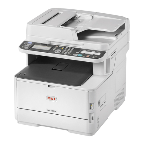
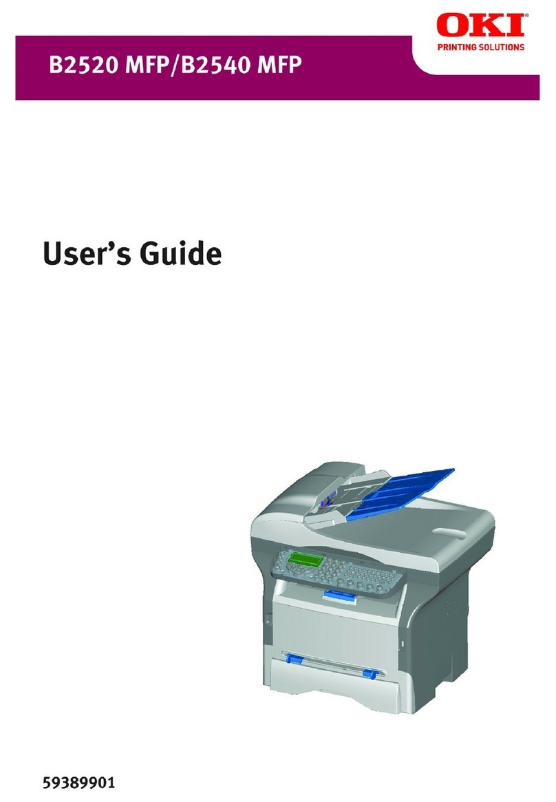
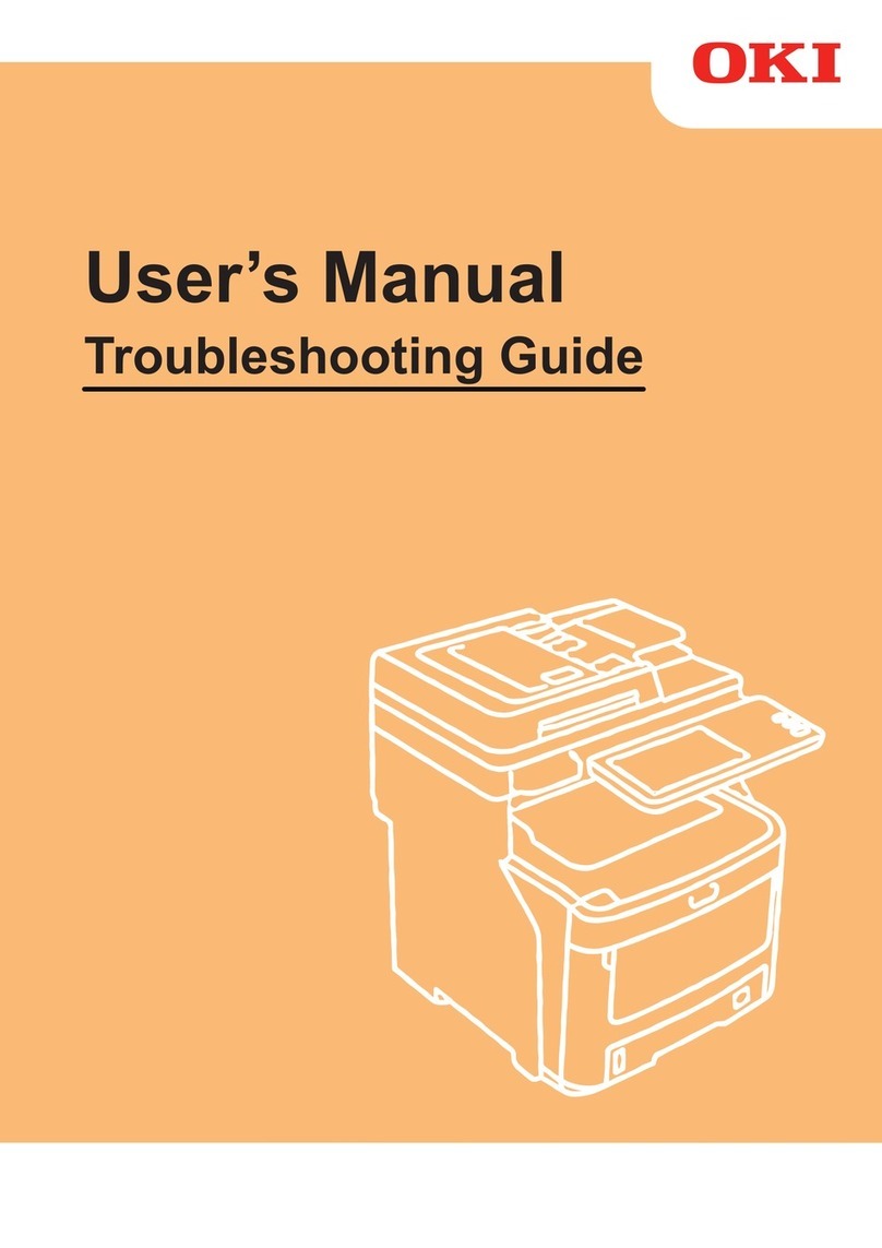
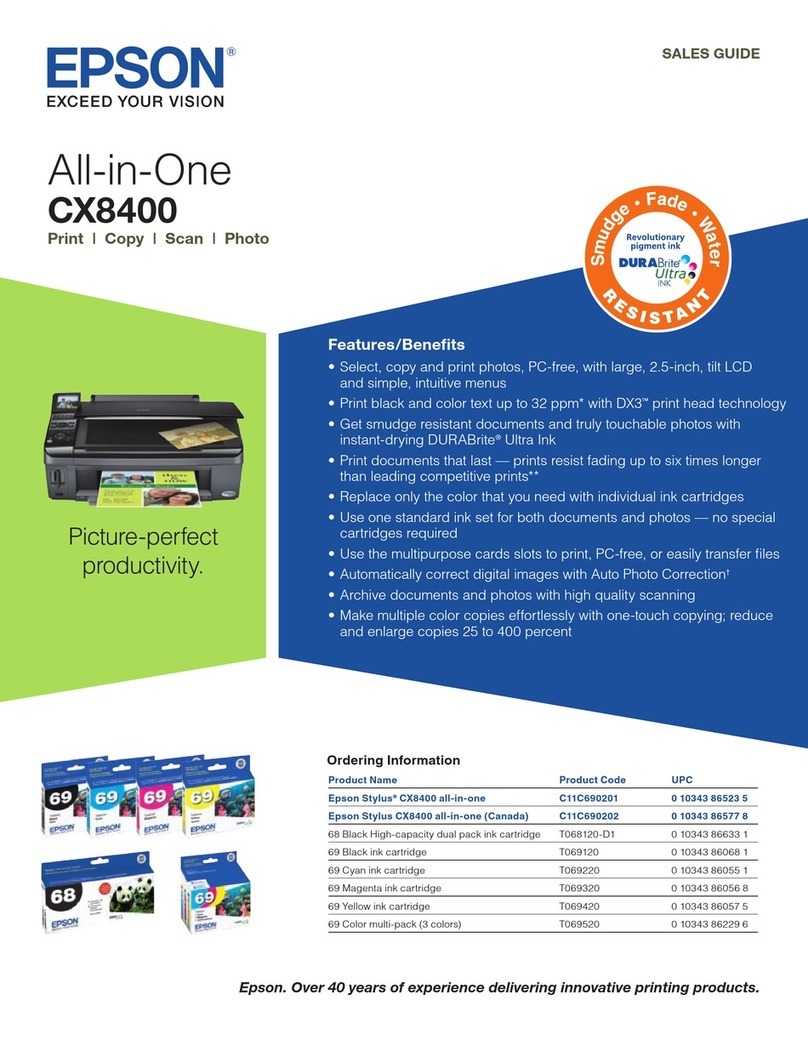
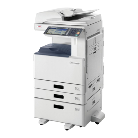
Oki MC-860 / CX2633MFP User manual

MC-860 / CX2633MFP
Service & Troubleshooting Guide
©2009 OkiData Americas, Inc.
Disclaimer
Every effort has been made to ensure that the information in this document is complete, accurate, and up to date. The
manufacturer assumes no responsibility for the results of errors beyond its control. While all reasonable efforts have been made
to make this document accurate and helpful as possible, we make no warranty of any kind, expressed or implied, as to the
accuracy or completeness of the information contained herein. For the most up-to-date service information available, visit our
website, www.okidata.com © Okidata Americas, Inc. 2009

2
Chapter 1 Maintenance Procedures – Printer / ADF / Scanner
1.1 Exterior Cleaning
1.2 Cleaning the LED lens array
1.3 Cleaning the Pickup Roller
1.4 Cleaning inside the Printer
1.5 Cleaning the ADF and Scanner
Chapter 2 Service Menus and Adjustments
2.1 How to Enter the Service Menu
2.2 Service Maintenance Menu Overview
2.3 System Maintenance
2.4 Panel Maintenance
2.5 Scanner Maintenance
2.6 Fax Maintenance
2.7 Printer Maintenance
2.7.1 Switch Scan Test
2.7.2 Motor & Clutch Test
2.7.3 Test Print - Monitoring Printer Environmental Conditions
2.7.4 Color Registration Error Correction Test
2.7.5 Density Error Correction Test
2.7.6 Consumable Item Counter Display
2.7.7 Factory/Shipping Mode Switching
2.7.8 Engine Parameter Setting – Fuse Check Method
2.8 Initialization Functions
Chapter 3 Troubleshooting Print Quality
3.1 Print Quality Problems Overview
3.2 Using New Consumable Units for Testing Purposes
3.3 Things to observe when analyzing Test Pages
3.4 Print-Quality Troubleshooting
Chapter 4 Troubleshooting Paper Feeding
4.1 Troubleshooting Paper Feed
4.1.1 Paper Feed Sensor Details
4.1.2 Jam Removal Procedure
Chapter 5 Troubleshooting Error Codes

Chapter 1 Maintenance Procedures – Printer
1.1 Exterior Cleaning
Clean inside and outside of the printer with a clean dry cleaning cloth and small vacuum cleaner as
required.
Note! Be careful not to touch the image drum terminals, the LED lens array and the LED head
connectors.
1. Turn OFF the power of the MFP.
Select “Setup” then “Shutdown”. Follow the on screen prompts. When shutdown is complete,
turn off the power switch on the printer.
2. Clean the surface of MFP.
3
Note! Do not use any liquid other than water and neutral detergent.
The MFP requires no lubrication.
Do not lubricate the unit.
Clean the surface of the unit with a clean
cloth wrung out using clean water or
neutral detergent.
Clean surface of the unit with soft clean cloth.

1.2 Cleaning the LED lens array
•Pull the document table lock lever to the front to release the lock, and raise the
document table.
Document Table
Document Table Lock Lever
•Press the top cover button and open the top cover.
CautionFailure to proceed with caution may result in burn injury. The fuser unit gets
very hot. Do not touch the surface of the fuser unit.
Top Cover Button
Top Cover
•Wipe the lens surface (at the four positions) of the LED head with soft tissue paper
gently and lightly.
4
Lens Surface of the LED Head
LED Heads

1.3 Cleaning the Pickup Roller
Note!Clean the pickup roller for tray 2 and tray 3 in the same procedure.
For the MP tray, clean the pickup roller in the same procedure for the feed roller only.
(Pad is not used.)
•Pull out the tray.
•Clean the feeder roller (large) and the feeder roller (small) with a clean cloth wrung
out using clean water
Feed Roller (Large)
Feed Roller (Small)
•Clean the pad portion of the tray with a clean cloth wrung out using clean water
T
ray 1
Pad
Roller
T
ray 2, Tray 3
5

1.4 Cleaning inside the Printer.
Toner can adhere to the metal shaft that is located in between the fuser and the cyan
image drum cartridge depending on the print pattern. Perform cleaning of the inside of
the MFP if toner has adhered to the metal shaft.
•Turn OFF the power of the MFP.
•Pull the document table lock lever to the front to release the lock, and raise
the document table. Then Press the top cover button and open the top cover.
•Remove the four image drum cartridges from the MFP.
Drum Cartridges
•Cover the removed image drum cartridge with a black paper.
Note! Use caution when handling the image drums. Be very careful not to expose the
image drum to direct sun light or intense light. Do not leave it out under normal
illumination even indoors for 5 minutes or longer.
•Remove the fuser unit from the MFP.
Caution Failure to proceed with caution may result in burn injury. The fuser unit gets
very hot. Do not touch the surface of the fuser unit.
•Raise the fuser unit lock lever (shown in blue) in the direction shown by the
arrow.
6

•Hold the handle of the fuser unit and remove it.
Fuser Handle
Fuser Unit Lock Lever (Blue)
•Remove the Transfer Belt unit from the MFP.
Transfer Belt
Retaining
Screws
(
Blue
)
Transfer Belt
•Thoroughly clean the interior of the printer and re-install the transfer belt,
fuser, and drum units. Inspect all units before re-installation.
7

1.5 Cleaning the ADF and Scanner
Clean the paper path of the ADF once every month or more in order to maintain high
print quality and to transport the documents smoothly.
•Open the document cover OPEN lever and open the document cover.
Document Cover Open Lever Document Cover
•Clean the document transport roller.
Clean surface of the roller with a clean cloth
wrung out using clean water or neutral
detergent.
.
Note! Clean the entire surface of the roller by rotating the roller by hand.
(Some types of rollers can rotate in one direction only.)
•Open the inside cover.
Clean surface of the roller with a clean cloth
wrung out using clean water or neutral
detergent.
Rollers Inside Cover
Dial
•Clean the document retainer roller.
8
Dial
Inside
top
cover
Clean surface of the roller with a clean cloth
wrung out using clean water or neutral
detergent.
Document
Retainer Roller

•Open the document table cover.
Platen Glass
Scanning Glass
Document
Retaining Pad
Clean the surface of the document retaining pad, the platen Glass and the scanning glass
with a clean cloth wrung out using clean water or neutral detergent.
9

Chapter 2 Service Menus and Adjustments
The service function is to be used for the purposes of MFP maintenance by the experienced
Maintenance / service engineer, and are not open to general users. The respective items of the service
function are contained in the service menu.
2.1 How Enter the Service Menu
Enter the service menu by the following operation.
1. The password entry screen is displayed when the special operation of the hardware keys is operated
while an MFP is running. The MFP enters this condition waiting for password entry.
2. When the password that is entered by maintenance/service engineer matches the specified password,
the service menu is displayed.
Special Operation of the Hardware Keys
The operation procedure to display the password entry screen of the service menu is described as
follows.
1. To display the password entry screen, press the [SETUP] key while an MFP is running.
2. Press the numeric keys in the order of [#] [1] [9] [3] [7].
3. The password entry screen is displayed.
Password Entry Screen
Value Default Display Condition
Enter the password that is required to enter the service menu. (OOOOOO) (Six zeros).
Note! Data entry will appear as
Asterisks.
10

Caution! The Password can be changed by the “Change Password” menu of the “System
Maintenance” menu. It is highly recommended that you DO NOT change this password. In the event
that the changed password is lost, the main control board and hard disk drive would need replacement.
This is not a covered expense under any machine warranty and you will incur the cost of the
replacement components.
Operation required to exit the Service Mode Screen
In order to complete operations of the service menu, the [Close] button that is displayed on the service
menu top screen should be pressed.
Note! If any setting change requires reboot of the MFP and the [Close] button is pressed, the MFP will
enter the normal operating condition after the MFP reboots.
11

2.2 Service Maintenance Menu – Overview
System Maintenance Screen Panel Maintenance Screen Copy Maintenance Screen
Scan Maintenance Screen Fax Maintenance Screen Printer Maintenance Screen
12

13
Service Maintenance Menu Structure is shown below.
Level 1 Level 2 Level 3 Level 4 Reboot
Process
OKIUSER When Closed
Format HDD When Executed
Format Flash ROM When Executed
Menu Reset None
All Reset When Executed
Test Print Menu
When Closed
System
Maintenance
(See Section 2.3)
Change Password New Password When Closed
Verify Password When Closed
LED Test None
LCD Test None
Panel
Maintenance
(See Section 2.4) OP Key Test None
Copy Maintenance Color Copy When Closed
Retrieve Shading Data None
Clean RADF Roller
None
Side Reg. NoneFBS
Front Edge None
Side Reg. None
Front Edge None
ADF (Front)
Back Edge None
Side Reg. None
Front Edge None
Scan
Maintenance
(See Section 2.5)
Adjust Scan Position
ADF (Back)
Back Edge None
Country Code When Closed
Echo support None
TX
Modem transmission speed None
Echo support None
RX
Modem transmission speed None
Pulse Make Ratio None
ON period None
MF(Tone) Duration
Off Period None
Calling Timer None
Attenuator None
MF Attenuator
None
Relay None
Tonal None
Fax Maintenance
(See Section 2.6)
Line Test
DTFM
None
IBM 5577 When Closed
IBM PPR III XL When Closed
EPSON FX When Closed
Personality
HP-GL/2 When Closed
Peak Control When Closed
Printer
Maintenance
(See Section 2.7)
Engine Diag. Mode
When Closed
Supplementary Description of “Reboot Process”
When Closed Reboot starts automatically when the [Close] button is pressed on the top screen of the service menu.
Reboot when executed Reboot starts automatically when the function is executed.
None Reboot is not executed and the screen moves into the normal operating condition when the [Close] button
is pressed on the top screen of the service menu.

2.3 System Maintenance
OKIUSER
Sets the MFP for the Destination Country.
Note! Should always be set for ODA (North America). Settings other than ODA may
result in erratic MFP operation. When the screen exits the service menu after this setting
is changed, the MFP reboots automatically.
Format HDD
Initialization of the HDD.
When [Format. HDD] is selected, the following confirmation screen is displayed.
When [Yes] is selected, the screen exits the menu and initialization of the HDD starts.
For details of the HDD initialization, refer to Section 2.8.
Format Flash ROM
Initialization of the Flash ROM.
When [Format Flash ROM] is selected, the following confirmation screen is displayed.
When [Yes] is selected, the screen exits the menu and initialization of the resident
mounted (on-board) Flash device starts.
For details of the Flash ROM initialization, refer to Section 2.8.
14

Menu Reset (Administrator Password Reset)
Returns the administrator password to the factory shipment setting (factory default) value.
When [Menu reset] is selected, the following confirmation screen is displayed. When
[Yes] is selected, the administrator password is reset to the factory shipment setting
(factory default) value.
For details of the administrator password reset, refer to Section 2.8.
All Reset
Returns the contents of the EEPROM, FLASH ROM and HDD to the factory shipment
setting (factory default) value. When [All Reset] is selected, the following confirmation
screen is displayed. When [Yes] is selected, the screen exits the menu, and contents of the
EEPROM, FLASH ROM and HDD are reset to the factory shipment setting (factory
default) value.
For details of the reset to the factory shipment setting, refer to Section 2.8.
Test Print Menu
Selects to display or not to display the menu [REPORT] – [PRINT] – [ID Check Pattern]
item, and [Engine Status] item. When [Disable] is selected in this setting, the [ID Check
Pattern] and [Engine Status] items are not displayed all the time. When the screen exits
the service menu after this setting is changed, the MFP reboots automatically.
15

Change Password
Note! The Password can be changed by the “Change Password” menu of the “System
Maintenance” menu. It is highly recommended that you DO NOT change this password.
In the event that the changed password is lost, the main control board and hard disk drive
would need replacement. This is not a covered expense under any machine warranty and
you will incur the cost of the replacement components.
2.4 Panel Maintenance
LED Test
All LED lamps are illuminated to check if any lamp is burned out or not.
Every time when the [SETUP] key is pressed, all LED lamps are turned ON and OFF.
Operating procedure
LED lamp = OFF Red LED lamp = ON
Green LED lamp = ON All LED lamps = ON
When the [Close] button is pressed, the screen returns to the panel maintenance menu.
16

LCD Test
Displays the test pattern on the LCD in order to check if there are inactive pixels on the
LCD.
Operating procedure
The following three kinds of test patterns can be displayed. To select the test patterns,
press the [SETUP] key.
Press the [SETUP]
key.
Press the [SETUP]
key.
Press the [SETUP]
key.
17

Control Panel Key Test
Checks if the MFP responds normally when the hardware key and the software key on
the control panel is pressed, by observing the LCD screen if the pressed key is displayed
or not on the LCD screen. This test aims at checking all of the keys. Therefore, all keys
should be pressed in the specified order in order to check that all keys have been pressed.
Operating procedure
When this test is selected, the panel key test screen is displayed as shown below. Press all
of the keys in the specified order as shown in the picture below.
When a key is pressed in the specified order, the following messages are displayed.
18
When a key is pressed in a wrong order, the following messages are displayed.

2.5 Scanner Maintenance
Shading Data Loading
Shading data of FBS and that of RADF (both-side copy model only) are loaded. This
item should be executed whenever any of the following items is performed.
•When the scanner lamp is replaced *
•When the mirror carriage adjustment is performed *
•When the scanner Main PCB is replaced
Operating procedure
When this item is selected Confirm that the RADF unit is closed.
the following screen is displayed. Then press the [Start] button.
Scanning Roller Cleaning
Operating procedure
When this item is selected, the following screen is displayed.
19

20
Scan Position Adjustment
Side registration adjustment - The separate setting items are prepared for FBS, ADF
(front side) and ADF (back side) independently.
Setting for Flat Bed Scanning (FBS)
Perform adjustment so that the scan start position in the horizontal scanning direction
during FBS Scanning stays within the reference value. Adjustment in increments of 1
item (5/600 dpi = 0.2117 mm) is possible in this setting. When a value is added in the
negative (-) direction, the scan image on a PC moves to the right. When a value is added
in the positive (+) direction, the scan image on a PC moves to the left.
Setting for ADF (front side)
Perform adjustment so that the scan start position in the horizontal scanning direction
during ADF front side scanning stays within the reference value. Adjustment in
increments of 1 item (5/600 dpi = 0.2117 mm) is possible in this setting. When a value is
added in the negative (-) direction, the scan image on a PC moves to the left. When a
value is added in the positive (+) direction, the scan image on a PC moves to the right.
Setting for ADF (rear side)
Perform adjustment so that the scan start position in the horizontal scanning direction
during ADF rear side scanning stays within the reference value. Adjustment in
increments of 1 item (5/600 dpi = 0.2117 mm) is possible in this setting. When a value is
added in the negative (-) direction, the scan image on a PC moves to the left. When a
value is added in the positive (+) direction, the scan image on a PC moves to the right.
Top End Position Adjustment
Perform adjustment so that the scan start position in the vertical scanning direction during
FBS scanning stays within the reference value. If shade is scanned at the top end of a
document, make adjustment in the positive direction. If deficiency occurs at the top end
of a document, make adjustment in the negative direction. Adjustment in increments of 1
item (0.1408 mm) is possible in this setting. When a value is added in the negative (-)
direction, the scan image on a PC moves down. When a value is added in the positive (+)
direction, the scan image on a PC moves up.
Setting for ADF (front side)
Perform adjustment so that the scan start position in the vertical scanning direction during
ADF front side scanning stays within the reference value. If shade is scanned at the top
end of a document, make adjustment in the positive direction. If deficiency occurs at the
top end of a document, make adjustment in the negative direction. Adjustment in
increments of 1 item (0.0619 mm) is possible in this setting. When a value is added in the
negative (-) direction, the scan image on a PC moves down. When a value is added in the
positive (+) direction, the scan image on a PC moves up.
Setting for ADF (back side)
Perform adjustment so that the scan start position in the vertical scanning direction during
ADF rear side scanning stays within the reference value. If shade is scanned at the top
end of a document, make adjustment in the positive direction. If deficiency occurs at the
top end of a document, make adjustment in the negative direction. Adjustment in
increments of 1 item (0.0619 mm) is possible in this setting. When a value is added in the
negative (-) direction, the scan image on a PC moves down. When a value is added in the
positive (+) direction, the scan image on a PC moves up.
Table of contents
Other Oki All In One Printer manuals