Oki OKIPOS 408II User manual

User’s Guide
moc.atadiko.ym59102601
RT322
OKIPOS 408II

Federal Communications Commission
Radio Frequency Interference
Statement
This device complies with Part 15 of the FCC Rules. Operation is subject to the following two conditions: (1) This
device may not cause harmful interference, and (2) this device must accept any interference received, including
interference that may cause undesired operation.
NOTE: This equipment has been tested and found to comply with the limits for a Class A digital device, pursuant to
Part 15 of the FCC Rules. These limits are designed to provide reasonable protection against harmful interference when
the equipment is operated in a commercial environment. This equipment generates, uses and can radiate radio frequency
energy and, if not installed and used in accordance with the instruction manual, may cause harmful interference to radio
communications. Operation of this equipment in a residential area is likely to cause harmful interference in which case
the user will be required to correct the interference at his own expense.
This statement will be applied only for the printers marketed in U.S.A.
FCC WARNING
Changes or modications not expressly approved by the party responsible for compliance could void the user’s
authority to operate the equipment.
For compliance with the Federal Noise Interference Standard, this equipment requires a shielded cable.
For RF interference suppression, if a ferrite core is provided with this device, afx it to the interface cable.
Statement of
The Canadian Department of Communications
Radio Interference Regulations
This Class A digital apparatus complies with Canadian ICES-003.
Cet appareil numérique de la classe A est conforme à la norme NMB-003 du Canada.
The above statement applies only to printers marketed in Canada.
©Copyright 2011 OKI Data Americas, Inc.

TABLE OF CONTENTS
1. Unpacking and Installation.....................................................................................................................1
1-1. Unpacking ....................................................................................................................................1
1-2. Choosing a place for the printer...................................................................................................2
2. Parts Identication and Nomenclature..................................................................................................3
3. Setup..........................................................................................................................................................4
3-1. Connecting the Cable to the PC ...................................................................................................4
3-2. Connecting the Cable to the Printer .............................................................................................5
3-3. Installing the Printer Software .....................................................................................................8
3-4. Connecting the Optional AC Adapter..........................................................................................9
3-5. Turning Power On......................................................................................................................10
3-6. Connecting to a Peripheral Unit.................................................................................................11
3-7. Loading the Paper Roll ..............................................................................................................12
4. Consumable Parts and AC Adapter.....................................................................................................17
4-1. Thermal Paper Roll ....................................................................................................................17
4-2. Thermal Label Paper Roll (Tack Label Paper) ..........................................................................19
4-3. AC adapter (option) ...................................................................................................................21
5. Control Panel and Other Functions .....................................................................................................22
5-1. Control Panel .............................................................................................................................22
5-2. Errors..........................................................................................................................................22
5-3. Self-Printing...............................................................................................................................24
6. Adjusting the Sensor..............................................................................................................................25
6-1. Adjusting the Near End Sensor Position....................................................................................25
6-2. PE and BM ( Paper End and Black Mark ) Sensor Adjustment ................................................27
6-3. NE (Near End) Sensor Adjustment............................................................................................28
7. Preventing and Clearing Paper Jams ..................................................................................................29
7-1. Preventing Paper Jams ...............................................................................................................29
7-2. Removing Paper Jam .................................................................................................................29
8. Periodical Cleaning................................................................................................................................30
8-1. Cleaning the Thermal Head .......................................................................................................30
8-2. Cleaning the Rubber Roller .......................................................................................................30
8-3. Cleaning the Sensors and the Surrounding Areas......................................................................30
8-4. Cleaning the Paper Holder and the Surrounding Area...............................................................30
9. Specications ..........................................................................................................................................31
9-1. General Specications..................................................................................................................31
9-2. Auto Cutter Specications .........................................................................................................32
9-3. Interface .....................................................................................................................................32
9-4. AC Adapter (Option) .................................................................................................................32
9-5. Environmental Requirements.....................................................................................................33
9-6. Reliability Specications ...........................................................................................................34
9-7. Black mark specications ..........................................................................................................35
10. Dip Switch Setting................................................................................................................................36
10-1.Parallel Interface Model..............................................................................................................37
10-2.RS-232C Interface Model ...........................................................................................................39
10-3. USB Interface Model .................................................................................................................42
10-4. EthernetInterface Model ............................................................................................................44
11. Parallel Interface..................................................................................................................................47

12. RS-232C Serial Interface.....................................................................................................................48
12-1. Interface Specications ..............................................................................................................48
12-2. RS-232C Connector ...................................................................................................................49
12-3. Cable Connections .....................................................................................................................51
12-4. Electrical Characteristics ...........................................................................................................51
13. USB and Ethernet Interface................................................................................................................52
13-1. USB Interface Specications .....................................................................................................52
13-2. Ethernet Interface Specications................................................................................................52
14. Peripheral Unit Drive Circuit .............................................................................................................53
15. Memory Switch Settings......................................................................................................................55
– 1 –
1. Unpacking and Installation
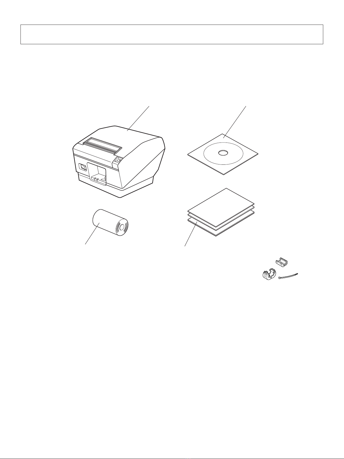
1-1. Unpacking
After unpacking the unit, check that all the necessary accessories are included in the package.
Note:The ferrite core and fastener provided with your
printer depend on your printer conguration.
Fig. 1-1 Unpacking
If anything is missing, contact the dealer where you bought the printer and ask them to supply
the missing part. Note that it is a good idea to keep the original box and all the packing materials
just in case you need to pack the printer up again and send it somewhere at a later date.
Note
Printer
Paper roll Setup sheets
CD-ROM

– 2 –
1-2. Choosing a place for the printer
Before actually unpacking the printer, you should take a few minutes to think about where
you plan to use it. Remember the following points when doing this.
P Choose a rm, level surface where the printer will not be exposed to vibration.
PThe power outlet you plan to connect to for power should be nearby and unobstructed.
PMake sure that the printer is close enough to your host computer for you to connect
the two.
PMake sure that the printer is not exposed to direct sunlight.
PMake sure that the printer is well away from heaters and other sources of extreme heat.
PMake sure that the surrounding area is clean, dry, and free of dust.
PMake sure that the printer is connected to a reliable power outlet. It should not be on
the same electric circuit as copiers, refrigerators, or other appliances that cause power
spikes.
PMake sure that the room where you are using the printer is not too humid.
WARNING
PShut down your equipment immediately if it produces smoke, a strange odor, or unu-
sual noise. Immediately unplug the equipment and contact your dealer for advice.
PNever attempt to repair this product yourself. Improper repair work can be dangerous.
PNever disassemble or modify this product. Tampering with this product may result in
injury, re, or electric shock.
– 3 –
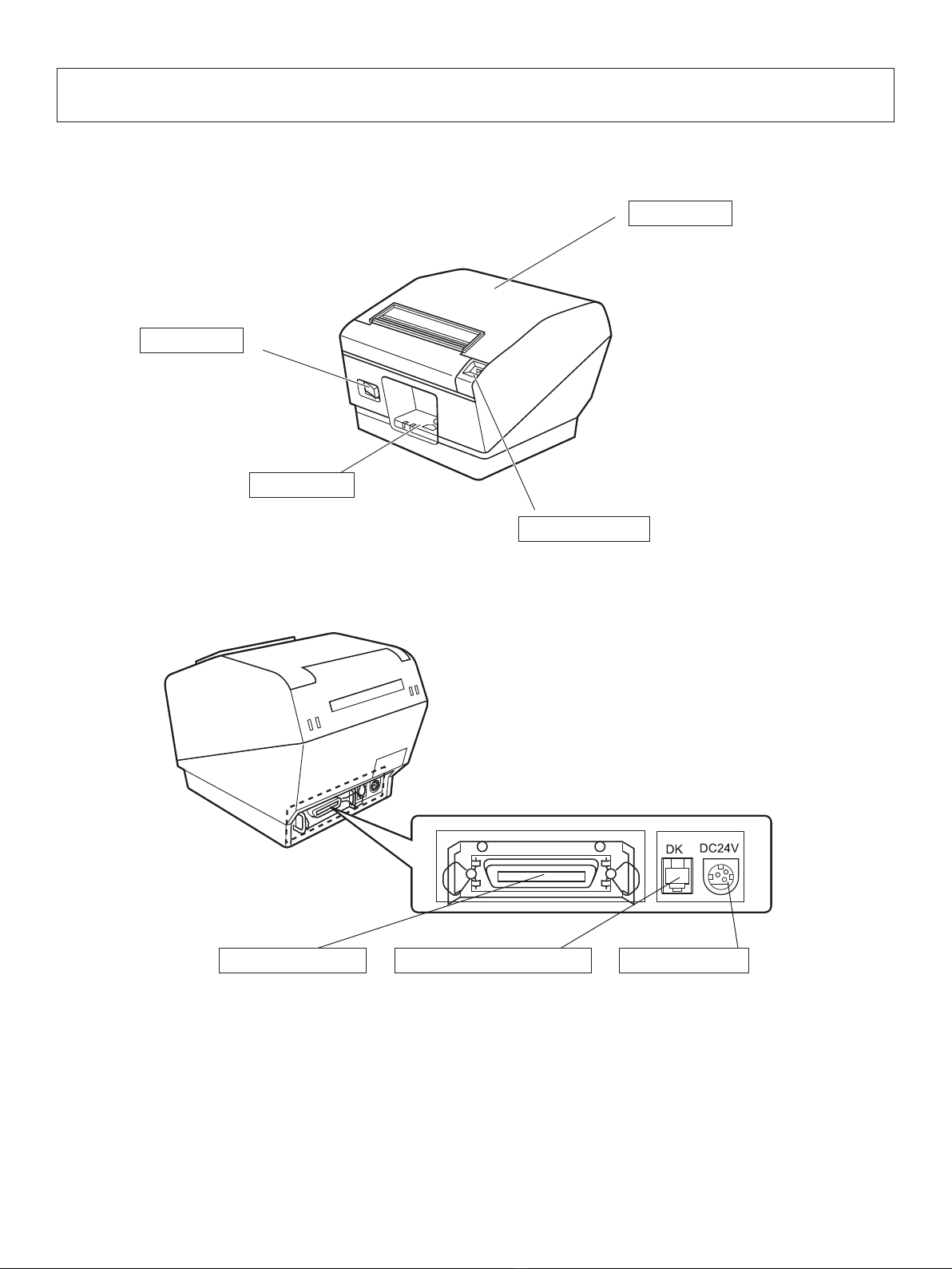
2. Parts Identication and Nomenclature
Interface connector
For connection to a
host computer.
Peripheral drive connector
Connects to peripheral units
such as cash drawers, etc.
Do not connect this to a
telephone.
Power connector
For connection of the
AC adapter.
Never unplug the
AC adapter while the
printer is on.
Printer cover
Open this cover to load
or replace paper.
Cover open lever
Push this lever in the direction of the
arrow to open the printer cover.
Power switch
Used to turn on/
off power to the
printer.
Control panel
Features LED indicators to
indicate printer status and
switches to operate the printer.
– 4 –
3. Setup
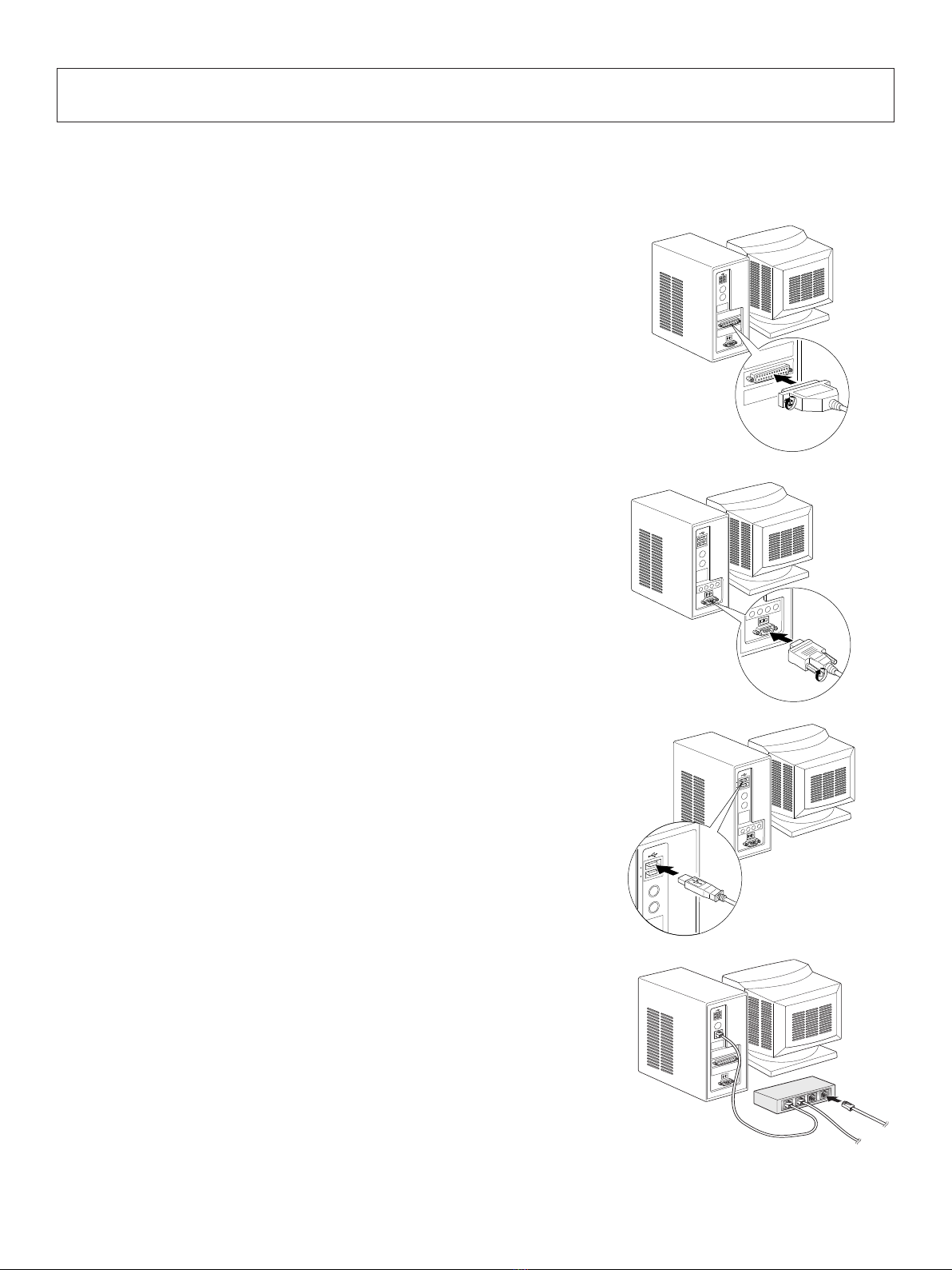
3-1. Connecting the Cable to the PC
3-1-1. Parallel Interface Cable
Connect the parallel interface cable to a parallel port
of your PC.
3-1-2. RS-232C Interface Cable
Connect the RS-232C interface cable to a RS-232C
port of your PC.
3-1-3. USB Interface Cable
Connect the USB interface cable to a USB port of
your PC.
3-1-4. Ethernet Interface cable
Connect the ethernet interface cable to a ethernet port
of your PC.

– 5 –
3-2. Connecting the Cable to the Printer
Note that the interface cable is not provided. Please use a cable that meets specications.
CAUTION
Before connecting/disconnecting the interface cable, make sure that power to the printer and
all the devices connected to the printer is turned off. Also make sure the power cable plug is
disconnected from the AC outlet.
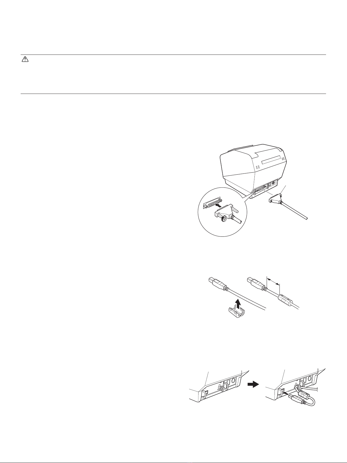
3-2-1. Parallel Interface Cable
(1) Make sure the printer is turn off.
(2) Afx the ferrite core onto the cable as shown in
the illustration.
(3) Pass the fastener through the ferrite core.
(4) Loop the fastener around the cable and lock it.
Use scissors to cut off any excess.
(5) Connect the interface cable to the connector on
the rear panel of the printer.
(6) Fasten the connector clasps.
Ferrite core
Interface cable
5 cm
(maximum)
Fastener
Parallel interface
cable
– 6 –
3-2-2. RS-232C Interface Cable
(1) Make sure the printer is turn off.
CAUTION
Before connecting/disconnecting the interface cable, make sure that power to the printer and
all the devices connected to the printer is turned off. Also make sure the power cable plug is
disconnected from the AC outlet.
(2) Connect the interface cable to the connector on the rear panel of the printer.
(3) Tighten the connector screws.
3-2-3. USB Interface Cable
Afx the ferrite core onto the USB cable as shown in
the illustration below and make sure to pass the cable
through the cable support as shown in the illustration.
RS-232C
interface
cable
4 cm (maximum)
Table of contents
Other Oki Printer manuals

Oki
Oki MICROLINE Turbo ML390 Owner's manual

Oki
Oki C130n User manual

Oki
Oki MPS730b Operating and maintenance instructions

Oki
Oki C3400n User manual

Oki
Oki ML8810 User manual

Oki
Oki C7300 User manual

Oki
Oki C3200n User manual

Oki
Oki B4400 Series User manual

Oki
Oki B710dn User manual

Oki
Oki MICROLINE 8810 User manual

Oki
Oki B720dn User manual

Oki
Oki PAGE 6E Reference guide

Oki
Oki C830dn Operation and maintenance manual

Oki
Oki C130n User manual

Oki
Oki OkiPos 407II User manual

Oki
Oki C5750 User manual

Oki
Oki C9650hdn User manual

Oki
Oki MAC TECHNICAL REFERANCE C7350 User manual

Oki
Oki ML521 Technical manual

Oki
Oki C711 Series Installation and operating instructions


