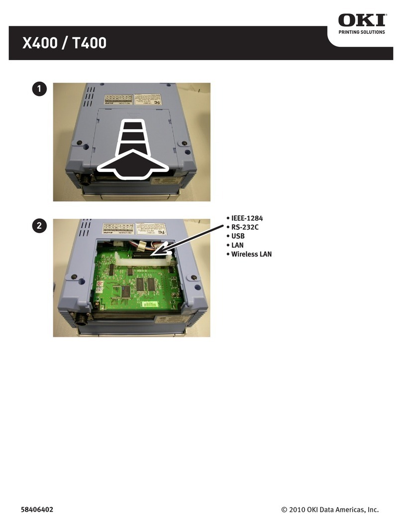
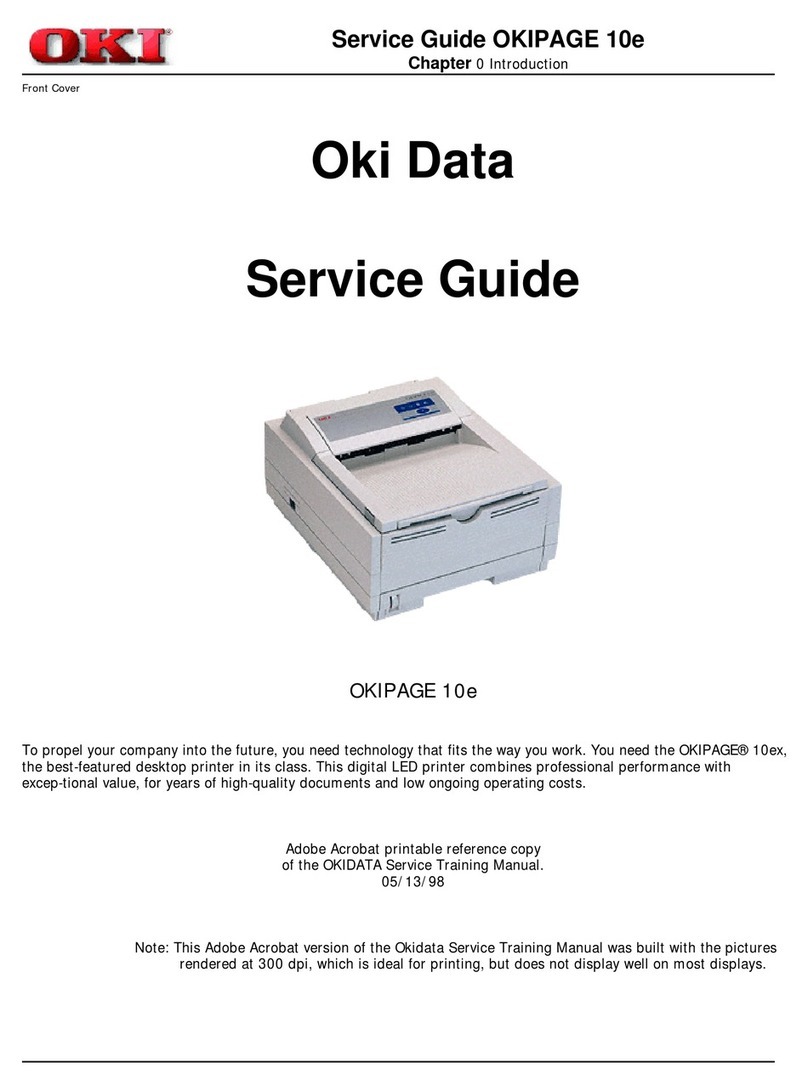
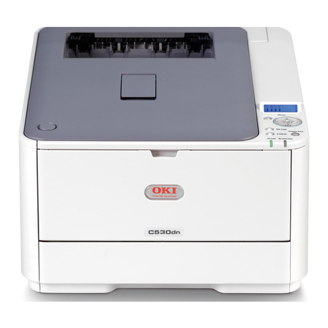
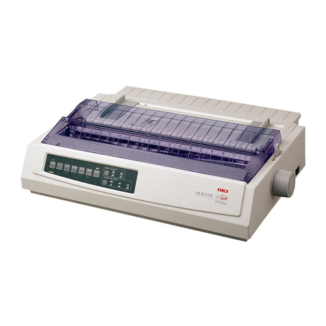
Oki T400 User manual


Copyright Information
Copyright © 2008by Oki Data. All Rights Reserved
Document Information ________________________________
T400/T410 User’s Guide
P/N 59307901, Revision 1.0
May, 2008
Disclaimer__________________________________________
Every effort has been made to ensure that the information in this document is
complete, accurate, and up-to-date. The manufacturer assumes no responsibility
for the results of errors beyond its control. The manufacturer also cannot guarantee
that changes in software and equipment made by other manufacturers and referred
to in this guide will not affect the applicability of the information in it. Mention of
software products manufactured by other companies does not necessarily
constitute endorsement by the manufacturer .
While all reasonable efforts have been made to make this document as accurate and
helpful as possible, we make no warranty of any kind, expressed or implied, as to
the accuracy or completeness of the information contained herein.
The most up-to-date drivers and manuals are available from the web site:
http://www.okiprintingsolutions.com
Trademark Information _______________________________
Oki and Oki Data are registered trademarks of Oki Electric Industry Company Ltd.
Apple, Macintosh and Mac OS are registered trademarks of Apple Computers Inc.
Hewlett-Packard, HP, and LaserJet are registered trademarks of Hewlett-Packard
Company.
Microsoft, MS-DOS and Windows are either registered trademarks or trademarks of
Microsoft Corporation in the United States and/or other countries.
Other product names and brand names are registered trademarks or trademarks of
their proprietors.

Warning
It is essential that the safety and operating procedures contained within
this manual be brought to the attention of, and are used by, all
personnel likely to operate this printer/product.
This printer/product must only be used for the purpose for which it was
designed.
This is a Class A product. In a domestic environment this product may
cause radio interference, in which case the user may be required to take
adequate measures.
Electrostatic discharges on the connector pins and on the memory card
may damage the printer.
In the case of fire, water must not be used on the product to extinguish
the fire, and the appropriate type of fire extinguisher should be readily
available.
No modifications, either mechanical or electrical, should be made to
this printer/product or accessory without the written consent of Oki
Data . Any modifications made without this consent may invalidate
guarantee claims.
Other manuals relating to this printer include additional information
relating to other aspects of the safe operation of the printer, and are
available from your Oki Data supplier.
All consumable waste, such as the label backing paper and used carbon
ribbon must be disposed of carefully, and in a manner that will cause
the minimum of environmental pollution.
Should you have any doubts regarding the setting, operating or any
safety aspects of this printer/product, please contact your Oki Data
supplier.
Oki Data makes no guarantee that all the features described in this
manual are available in all models. Due to Oki Data’s policy of
continuous development and improvement, specifications are liable to
change, without notice.

Consumables
Always use Oki Data carbon ribbons or equivalent. The use of incorrect
materials could a cause malfunction of the printer and void the
warranty.
Warranty and Copyright
Oki Data makes no guarantee of any kind with regard to this material,
including, but not limited to, the implied guaranties of merchantability
and fitness for a particular purpose.
Oki Data shall not be liable for errors contained herein or for any
incidental, consequential damages in connection with the furnishing,
performance, or use of this material.
This document contains proprietary information which is protected by
copyright.
All rights are reserved.
No part of this document may be reproduced or issued to third parties
in any form whatsoever without the express permission of Oki Data.
The information in this document is subject to change without notice.
© Copyright 2007 Oki Data Corporation


i
Contents
1. Overview ······································································································ 1
1.1 Technical Data······················································································ 1
1.2 Name of Parts······················································································· 2
1.2.1 Front View················································································· 2
1.2.2 Back View ················································································· 4
1.2.3 Top Cover Open········································································· 5
1.2.4 Front Cover Open······································································ 7
2. Connections·································································································· 9
2.1 Power Connection················································································· 9
2.2 Power On/Off ····················································································· 10
2.3 Printer Status Printout··········································································11
2.4 Computer Connection········································································· 12
2.4.1 Bi-directional parallel interface (standard)······························· 12
2.4.2 Optional interface (RS232C) ··················································· 13
2.4.3 Optional Interface (USB)························································· 14
2.4.4 Optional Interface (LAN) ························································ 15
3. Configuration······························································································ 17
3.1 Status Monitor···················································································· 17
3.2 DIP-SW Settings················································································· 21
3.2.1 Change Settings······································································· 22
4. Media Setting······························································································ 27
4.1 Ribbon Setting (Thermal Transfer only) ············································· 27
4.2 Paper Setting······················································································· 30
4.2.1 Standard and Cutter ································································· 30
4.2.2 Installing the Cutter Kit ··························································· 33
4.2.3 Dispenser················································································· 36
4.2.4 Installing the Dispenser Kit······················································ 40
5. Maintenance ······························································································· 52
5.1 Using the Oki Data Cleaning Kit ························································ 53
5.2 Using the lapping film ········································································ 54
6. Troubleshooting·························································································· 56
6.1 Print Difficulties················································································· 56
6.2 Paper is fed but does not print····························································· 56
6.3 Printout is not clear············································································· 57
6.4 When you confirm the printer settings················································ 57
6.5 When the Error Light is on ································································· 58
6.6 Error Number and its reason······························································· 58
6.7 Failure?······························································································· 59


1
1. Overvie
nic
T410
w
1.1 Tech al Data
T400
Print Type yDirect Thermal/ Thermal Transfer, Direct Thermal onl
Resolution 0.125 mm (8 dot/mm, 203 dpi) 0.083 mm (12 dot/mm, 305 dpi)
Speed User s lectable
2 to 6 ips User selectable
2 to 4 ips
e
from 50 mm/sec to 150 mm/sec from 50 mm/sec to 100 mm/sec
Darkness 5 / 6 steps selectable (by Printer Driver)
Print Area Print width 104 mm (4.1 in.) x
5.6 in.) Print width 104 mm (4.1 in.) x
400 mm (15.6 in.)400 mm (1
Media Width 25 (0.98 in.) ~ 115 mm (4.5 in.)
.1 in.) ~ 118 mm (4.6 in.) incl. Backing paper)(28 (1
Media Length and Batch:
Calliper Dispense:
Cutter:
Tear-Off
15 (0.6 in.) ~ 397 mm (15.6 in.) (18 (0.71 in.) ~400 mm (15.6
in.) incl. Backing paper) 0.08 (0.003 in.) ~ 0.19 mm (0.075 in.)
20 (0.78 in.) ~ 120 mm (4.7 in.) (23 (0.91 in.) ~ 123 mm (4.8
in.) incl. Backing paper) 0.08 (0.003 in.) ~ 0.19 mm (0.075 in.)
20 (0.78 in.) ~397 mm (15.6 in.) (23 (0.91 in.) ~400 mm (15.6
in.) incl. Backing paper) 0.08 (0.003 in.) ~ 0.19 mm (0.075 in.)
27 (1.06 in.) ~ 397 mm (15.6 in.) (30 (1.18 in.) ~ 400 mm (15.6
in.)incl. Backing paper) 0.08 (0.003 in.) ~ 0.19 mm (0.075 in.)
Label Roll Maximum Roll Diameter: 110 mm (4.3 in.) (Face out)
Label Inner Core Diameter: 40 mm (1.6 in.)
Media Types Die-Cut Label; Continuous material; Tag material, Roll type- Face-
out, Fan fold type, 2 color thermal paper
Carbon Ribbon 100 meter (325 ft.) long, Face out, I.D. 12.7 mm (0.5in.),
O.D. 39 mm(1.5 in.), Thickness: 4.5 Micron, black and colored up to
111 mm (4.4 in.) wide, center adjustment
Bar-Codes UPC-E / UPC-A, NW-7, Code 39, Code 93, Code 128, UCC / EAN
128, ITF 2 of 5, Industrial 2 of 5, Matrix 2 of 5, MSI, Bookland, Post-
net, RSS Composite Code
Bar-C :3, 2:5ode Ratios 1:2, 1
Bar-Cod Sizes Height: 4 dots to 600 dots; width – user definablee
Rotational capability 360° Rotation (0°, 90°, 180° and 270°)
2-D C Code, PDF 417, Micro PDFodes QR Code, Veri Code, Maxi
Fonts Outline FontU, S, M, XU, XS, XM, XB, XL, OCR-A, OCR-B,
Label nSe sing Reflective Sensor (eye-mark) bottom reading
(Gap) movableSee-through sensor
CPU 32 bit RISC / 80MHz
Memo te; Expanded: Flash-ROM 2 x 2Mbytery Standard: Flash-ROM 2MBy
Capacit Input Buffer 2.9MByte, SDRAM 8MBytey
Interface ECP Parallel (IEEE1284),RS232C, USB, LAN, Wireless LAN

2
witches: ONLINE Key; FEED Key, PowerOperation S
Setting Switches: 1 x 8 Dip-Switches
Front Panel
LED: POWER, ONLINE, ERROR
Dimen .); Width: 198 mm (7.8 in.);sions Height: 18
Depth: 230 mm (9.1 in.)
1 mm (7.1 in
Weight 3.0 kg (6.6 lbs.)
Power Hz, 90W (30% utilisation)110 - 240V +/- 10%, 50/60
Enviro 5 ~ +35° C, Humidity 30 ~ 80% RH non-Condensingnmental Operating: +
Conditions Storage: -5 ~ +45° C, Humidity 20 ~ 90% RH non-Condensing
Approvals CE, UL, CSA, TÜV-GS
Options Cutter, Dispenser
1.2 Na
1.2.1
me of Parts
ront ViewF
1. Top Cover
Open this cover when you position the paper or insert a new carbon
ribbon (thermal transfer only).
2. Power Switch
Press this switch to turn ON/OFF the printer.
3. Paper Check Window
To check the status of paper.
4. Front Cover
Open this cover to check the DIP-SW Settings and the printer status
or to install an optional dispenser or label cutter.

3
5. Operation Switches and LEDs
•POWERLED
When you turn on the power, the green light comes on.
Refer to “Connections”.
• ERROR LED
When an error occurs, the red light comes ON.
Refer to “Troubleshooting”.
•ONLINELED
When the green light is ON, the printer can receive data. When
the light is OFF, the printer cannot receive data.
• ONLINE Button
Press this button to stop receiving data. Resume by pressing
this button again. If this button is pressed while printing, the
printing is suspended. To resume printing, press this button
again.
• FEED Button
When you press this button in the offline state, you can feed
paper. If you turn on the power of the printer while simultane-
ously pressing this button you can print out the printer status.

4CT400/410
1.2.2 Back View
1. Power Connector
AC adapter connector.
2. Fanfold Paper Inlet
Open this to use fanfold paper.
3. Interface Connector

Operation Manual Overview
CT400/410 5
1.2.3 Top Cover Open
Thermal Transfer
Direct Thermal
9
1
3
2
4
511
6
8
7
9
1
2
4
5
3
6
8
10
11

6CT400/410
Overview Operation Manual
1. Paper Holder
When you use a roll of paper, insert the paper here. You can
adjust the width according to the paper size.
2. Paper Holder Slide Lever
Press this lever to adjust the paper holder width.
3. Head
Open this part to refill paper and the carbon ribbon (thermal
transfer).
4. Head Open/Close Lever
Press this to open the head.
5. Front Cover
Pull to open (Page 7).
6. Platen Roller
This is the part that feeds paper serving as platen roller for the
print head. Please keep this part clean.
7. Ribbon Unit
Set the ribbon here.
8. Sensor
Paper moves through this sensor.
9. Tool for Darkness Adjustment
This tool can be used for adjusting the potentiometers and the
DIP-SW settings.
10. Upper Cutter Edge of the Cutter Unit (Cutter Version Only)
The upper part of the cutter unit is installed here. Please keep
it clean.
11. Backing Paper Outlet (Dispenser version only)
Backing paper is dispensed through this opening.

Operation Manual Overview
CT400/410 7
1.2.4 Front Cover Open
1. Print Darkness and Offset Adjustment Volume
Depending on the DSW 6 setting you can either set the Print
Darkness or the Label Offset (Label Stop Position).
2. Label Sensor Adjustment
Do not use this. Only for use by service personnel.
3. DIP-SW
Appropriate settings are set according to your printer system
environment. You can change the settings.
Refer to “Configuration“.
4. Error Number Display
When the error light is ON, check the displayed number. This
number represents the cause of error.
Refer to “Troubleshooting” for more details.
5. Pitch Adjustement
Standard
Cutter (optional)
Dispenser (optional)

8CT400/410
Overview Operation Manual
This page is intentionally left blank.

Operation Manual Connections
CT400/410 9
2. Connections
2.1 Power Connection
1. Connect the power cable with the main unit and AC adapter as
shown in the figure. When you insert the AC adapter in the main
unit, set the stopper firmly.
2. Plug in the power cable to the outlet.
Stopper

10 CT400/410
Connections Operation Manual
2.2 Power On/Off
• Press the power switch at the front side of the main unit in the
“I” direction.
• When you turn on the power, the POWER light comes on.
Please make sure that the light is on.
• When you turn off the printer, flip the switch to the “0” direction.
Power Switch

Operation Manual Connections
CT400/410 11
2.3 Printer Status Printout
The printer status can be printed out.
The current status settings are printed to confirm the settings.
1. Turn ON the power of the printer while pressing the FEED but-
ton.
2. Whenabuzzer isheard,releasethe FEEDbuttonandpress the
following button:
ONLINE to print in large size.
FEED to print in small size.
3. The printer settings are printed.
Appropriate settings are set according to your printer (Default
settings). Please compare the standard values with the printout
to confirm the settings.
• To stop printing press the FEED button. Press the FEED button
again to resume printing.
• To leave this mode turn off the printer. Before turning off the
power of the printer, confirm that the printing process has
stopped.
Power Switch
ONLINE Button
FEED Button

12 CT400/410
Connections Operation Manual
2.4 Computer Connection
2.4.1 Bi-directional parallel interface (standard)
1. Turn off the power of the printer. Using an interface cable con-
nect the computer to the bi-directional parallel interface connec-
tor at the rear panel of the printer.
2. Be sure to use a IEEE1284 compatible cable.
Wire Connection Table for IEEE1284 compatible cable:
Host
1
2
3
4
5
6
7
8
9
10
11
12
13
14
32
31
36
33
19
21
23
25
27
29
30
Shield
Printer
1
2
3
4
5
6
7
8
9
10
11
12
13
Host Printer
14
15
16
17
18
19
20
21
22
23
24
25
Shield
Strobe
D0
D1
D2
D3
D4
D5
D6
D7
AKN
Busy
PE
Select
LF
Error
Init
Select in
GND
GND
GND
GND
GND
GND
GND
GND

Operation Manual Connections
CT400/410 13
2.4.2 Optional interface (RS232C)
Connecting the printer to your computer.
1. Turn off the power of the printer. Using an interface cable con-
nect the computer to the optional interface connector at the rear
panel of the printer.
2. Interface Cable
The wire connection varies depending on the communication
product.
Prepare an appropriate cable for the communication protocol.
Connector: D-SUB-25S.
Cable length: Less than 5 meters.
ER Control
1
2
3
4
5
6
7
20
2
3
4
5
6
7
20
1Status 3/4
1
2
3
4
5
6
7
20
2
3
4
5
6
7
20
1
Other manuals for T400
4
This manual suits for next models
1
Table of contents
Other Oki Printer manuals
Popular Printer manuals by other brands

Siemens
Siemens TELEPRINTER 100 operating instructions

Panasonic
Panasonic KX-PX20M - Photo Printer - 20 Sheets quick guide

Epson
Epson Stylus Color C70 Setup

AMT Datasouth
AMT Datasouth Documax 5380 quick start guide

Lexmark
Lexmark T650dtn quick reference

Gedge Systems
Gedge Systems GS8920 Operating & installation manual