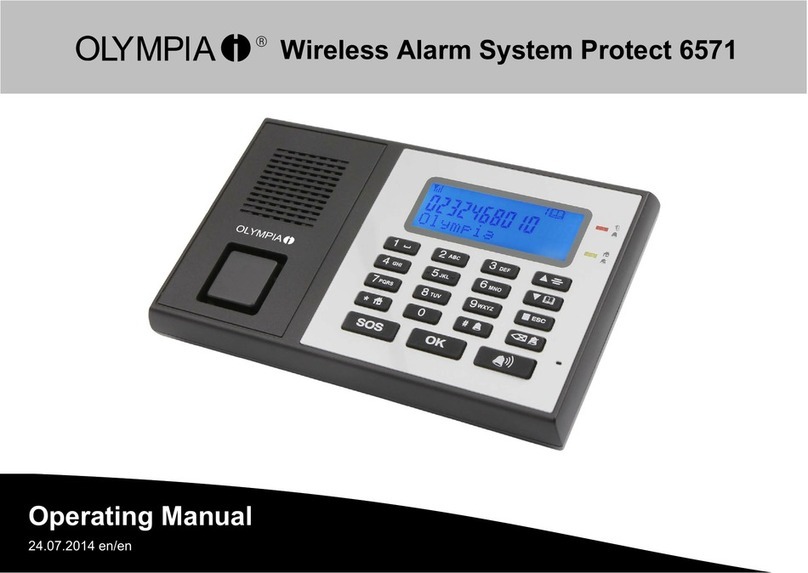
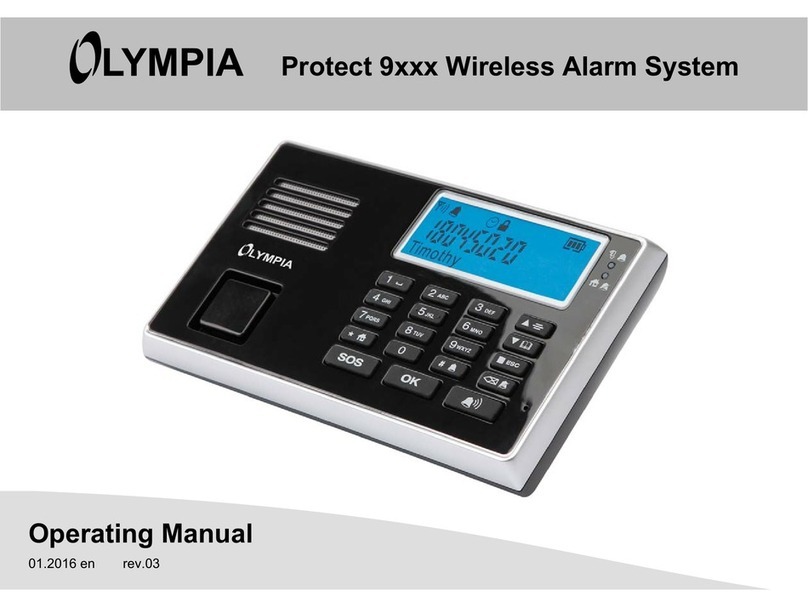
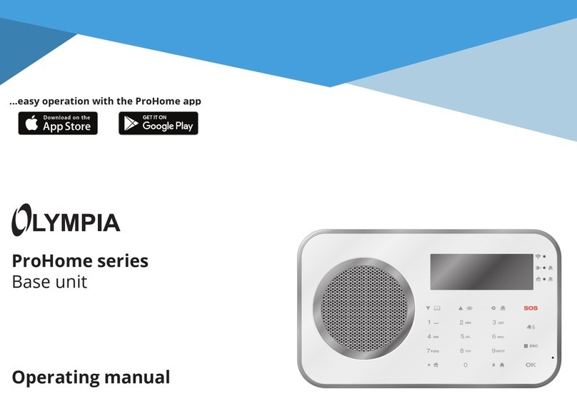
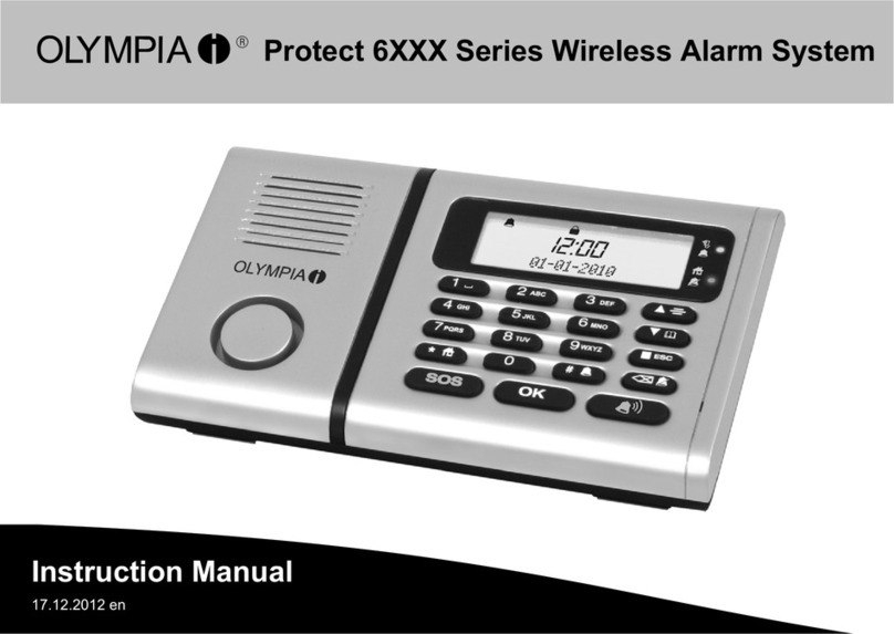
Olympia Protect Series User manual

Protect Series
Base Unit
Operating Manual


Hello,
We are delighted that you have decided to
purchase this reliable device from Olympia.
The descriptions on the following pages will
explain how easy it is to make your home
more safe and secure.

4PROTECT
Content
Before You Start . . . . . . . . . . . . . . . . . . . . . . 6
Safety Instructions . . . . . . . . . . . . . . . . . . . . 7
Intended Use . . . . . . . . . . . . . . . . . . . . . . . . . 9
Scope of Delivery . . . . . . . . . . . . . . . . . . . . . . 9
Overview of Base Unit . . . . . . . . . . . . . . . . 10
Front . . . . . . . . . . . . . . . . . . . . . . . . . . . . . . . . 10
Rear . . . . . . . . . . . . . . . . . . . . . . . . . . . . . . . . . 11
Display . . . . . . . . . . . . . . . . . . . . . . . . . . . . . . . 12
Keys and Operating Elements . . . . . . . . . . . 13
Control Lamps. . . . . . . . . . . . . . . . . . . . . . . . . 14
Overview of Remote Control. . . . . . . . . . . 14
Menu Structure . . . . . . . . . . . . . . . . . . . . . . 15
Putting the Base Unit into Operation . . . 16
Positioning the Base Unit . . . . . . . . . . . . . . . 16
Inserting the SIM Card (Option) . . . . . . . . . . 17
Inserting the Batteries (Option) . . . . . . . . . . 18
Connecting the Power Adapter . . . . . . . . . . 19
Setting Up the Base Unit . . . . . . . . . . . . . . 20
Setting the Key Lock. . . . . . . . . . . . . . . . . . . . 20
Setting the Language . . . . . . . . . . . . . . . . . . . 21
Setting the Time and Date. . . . . . . . . . . . . . . 21
Registering Sensors . . . . . . . . . . . . . . . . . . . . 22
Deregistering Sensors . . . . . . . . . . . . . . . . . . 23
Renaming Sensors . . . . . . . . . . . . . . . . . . . . . 23
Individual Voice Message . . . . . . . . . . . . . . . 23
&RQȴJXULQJWKH7HOHSKRQH8QLW. . . . . . . . . . 24
Saving Alarm Call Numbers. . . . . . . . . . . . . . 25
Saving an SOS (Emergency Call) Number . . 26
Testing the Telephone Unit. . . . . . . . . . . . . . 26
Setting the Trigger Delay . . . . . . . . . . . . . . . . 27
Setting the Arming Delay. . . . . . . . . . . . . . . . 28
Setting the Alarm Period . . . . . . . . . . . . . . . . 28
Switching the Warning Signal from the
%DVH8QLW2Q2 . . . . . . . . . . . . . . . . . . . . . . 28
Setting the Key Tone . . . . . . . . . . . . . . . . . . . 29
Setting the Volume of the Voice Output . . . 29
Setting the Contrast . . . . . . . . . . . . . . . . . . . . 29

5
PROTECT
Monitoring Functions . . . . . . . . . . . . . . . . . 30
Alarm Mode. . . . . . . . . . . . . . . . . . . . . . . . . . . 31
At Home Mode . . . . . . . . . . . . . . . . . . . . . . . . 31
Silent Mode . . . . . . . . . . . . . . . . . . . . . . . . . . . 32
Disarmed Mode . . . . . . . . . . . . . . . . . . . . . . . 32
Panic Alarm . . . . . . . . . . . . . . . . . . . . . . . . . . . 33
Emergency Call (SOS) . . . . . . . . . . . . . . . . . . . 33
PIR At Home Mode . . . . . . . . . . . . . . . . . . . . . 34
Smoke and Water Detectors. . . . . . . . . . . . . 35
Function of the Key . . . . . . . . . . . . . . . . . 35
Remote Access by Phone . . . . . . . . . . . . . . 36
Appendix . . . . . . . . . . . . . . . . . . . . . . . . . . . . 37
Restoring the Default Factory Settings . . . . 37
Changing the Battery . . . . . . . . . . . . . . . . . . . 37
System Extensions . . . . . . . . . . . . . . . . . . . . . 37
Technical Data - Base Unit. . . . . . . . . . . . . . . 38
Technical Data - Remote Control . . . . . . . . . 38
Cleaning and Service . . . . . . . . . . . . . . . . . . . 38
Information on Disposal . . . . . . . . . . . . . . . . 39
Guarantee . . . . . . . . . . . . . . . . . . . . . . . . . . . . 39
Information on Conformity. . . . . . . . . . . . . . 39

6PROTECT
BEFORE YOU START
Before You Start
The alarm system is a passive security product and has been conceived as a deterrent. Additional measures are
necessary to prevent and hinder burglary and theft.
You can obtain all the necessary information on this from your local police station.
You can increase security by integrating additional sensors from the Olympia range. We also provide outdoor sirens,
door/window contacts, motion detectors, vibration sensors, water detectors, glass breakage detectors and much
more.
<RXFDQȴQGPRUHLQIRUPDWLRQRQVHFXULQJ\RXUKRPHRQRXUZHEVLWHwww.olympia-vertrieb.de
Read the operating manual thoroughly and observe all the information contained when using the alarm
system. Keep the operating manual in a safe place for future reference.
Pay attention to this symbol. Texts which are highlighted by this symbol provide helpful information on
handling the alarm system.

7
PROTECT
SAFETY INSTRUCTIONS
Safety Instructions
The following warnings apply to the entire document.
Read and observe all the warning information to protect
yourself and the environment from any harm.
The following warnings indicate potentially dangerous sit-
uations which could lead to serious injuries or even fatal
injuries if the information is ignored.
WARNING!
Risk of fatal injury from electric shock! NEVER use
the device if you suspect damage to the power
cable or power plug or there are visible signs of
damage to the power cable or power plug.
NEVER complete any repairs to the device yourself.
Never open the device because it contains no
components which you may service yourself. In the
event of a fault, contact our Service Department.
WARNING!
5LVNRIVXRFDWLRQ&KLOGUHQFDQVZDOORZVPDOO
parts, packaging and protective foils. Keep the
device and packaging out of reach of children.
WARNING!
Risks to health through batteries! Keep batteries
out of reach of children. Do not swallow batteries. If
any type of battery or round cell is swallowed, seek
medical attention immediately.
WARNING!
Risk of explosion! Improper storage of batteries can
put your health and the environment at risk.
Batteries may contain toxic, ecologically hazardous
heavy metals. Never open, damage or swallow
batteries or allow them to pollute the environment.

8PROTECT
SAFETY INSTRUCTIONS
The following warnings indicate potentially dangerous
situations which could lead to minor or slight injuries if
the information is ignored.
CAUTION!
This device can be used by children from the age of
bDQGSHUVRQVZLWKUHVWULFWHGSK\VLFDOVHQVRU\RU
mental capabilities or a lack of experience and
knowledge as long as they are supervised or have
been instructed with regard to safe use of the
device and are aware of the potential risks involved
with its use. Children must never play with the
device. Cleaning and user maintenance may not be
completed by children without any supervision.
CAUTION!
Hearing damage through loud alarm signal! Due to
legal requirements, the alarm signal continues for
PD[LPDOO\bVHFRQGV7KHDODUPVLJQDOVZLWFKHV
RDXWRPDWLFDOO\DIWHUDERXWbVHFRQGVLIWKH
user does not interrupt it. Use ear protectors when
testing the device. Do not remain in the vicinity of
the acoustic alarm for a longer period when it has
been triggered.
The following warnings indicate potentially dangerous
situations which could lead to property damage if the
information is ignored.
ATTENTION!
Property damage through the use of inappropriate
batteries! The use of inappropriate batteries can
cause a loss of function of the device. Only use
batteries of the type described in Section "Technical
Data".
ATTENTION!
3URSHUW\GDPDJHWKURXJKHQYLURQPHQWDOLQȵXHQF-
HV3UHYHQWHQYLURQPHQWDOLQȵXHQFHVVXFKDV
exposure to smoke, dust, vibration, chemicals,
moisture, heat and direct sunlight.

9
PROTECT
INTENDED USE
Intended Use
The alarm system in the Protect Series is suitable for
monitoring rooms and houses, as long as there is a reli-
able wireless connection to the registered sensors (e.g.
door/window contacts, smoke detector).
A condition for complying with the intended use is that
the equipment is installed correctly and the information
in the manual is observed and maintained.
Any other use is considered unintended use.
This operating instruction manual contains important
information on setting up and handling the equipment.
Always hand over this operating manual if the alarm sys-
tem is transferred to others.
Scope of Delivery
Please check the contents of the package carefully. If any-
thing is missing or has been damaged during transport,
DO NOT put the alarm system into operation! Keep the
packaging in a safe place to protect the equipment from
damage should it need to be dispatched in future.
Base unit
Power adapter
Remote control
Batteries [DONDOLQHEDWWHULHV$$$b9
1 x round cell battery, CR2032
Assembly material Base unit legs, screws, dowels
Operating manual

10 PROTECT
OVERVIEW OF BASE UNIT
Overview of Base Unit
Front
1
2
3
4
5
1Display 4Function keys
2Loudspeaker 5Digit keys
3Control lamps

11
PROTECT
OVERVIEW OF BASE UNIT
Rear
1
2
3
4
5
6
7
10
9
8
1Rubberised base unit legs 6Battery compartment cover
2Recesses for mounting bracket 7Connection port for power adapter
3Battery compartment 8Connection for external antenna (option)
4Compartment for SIM card 9Antenna switch
5MicroUSB connection port 10 Reset key

12 PROTECT
OVERVIEW OF BASE UNIT
Display
4
3
2
1
6
5
7
8
9
10
11
12
13
14
1Delay activated (arming, triggering, key lock) 8More information in plain text (e.g. Register)
2Telephone unit activated for emergency call (SOS) 9Key lock activated
3At Home mode activated 10 Telephone unit activated
4Alarm mode activated 11 Recorded message playing
5Silent mode activated 12 Storage location of phone number
6Display of the network availability 13 Save icon
7Display for plain text (e.g. 19:09)14 Base unit battery is almost empty

13
PROTECT
OVERVIEW OF BASE UNIT
Keys and Operating Elements
The following table indicates the functions assigned to
the individual keys and operating elements on the front
of the base unit of the alarm system.
SOS key
&RQȴUPHQWULHV
Panic key
Open the menu; navigate in the menu; in-
crease the loudspeaker volume in Hands-
free mode
Open Save mode for alarm phone num-
bers; navigate in the menu; reduce the
loudspeaker volume in Handsfree mode
Disarmed mode key; exit the menu; stop
the countdown
-Silent mode key; delete input
Alarm mode key
At Home mode key
Digit keys to enter your settings

14 PROTECT
OVERVIEW OF REMOTE CONTROL
Control Lamps
7KHIROORZLQJWDEOHLQGLFDWHVWKHȵDVKLQJDQGOLJKWXS
behaviour of the control lamps on the front of the base
unit of the alarm system.
Operation via power adapter
Top LED Bottom LED
Silent mode Lights up Flashing
Alarm mode Flashing 2
At Home mode Lights up Lights up
Disarmed mode Lights up 2
Operation with batteries
Top LED Bottom LED
Silent mode 2 Flashing
Alarm Mode Flashing 2
At Home Mode 2 Lights up
Disarmed Mode 2 2
Overview of Remote Control
The remote control enables you to switch monitoring
IXQFWLRQVRQDQGRWULJJHUD3DQLFDODUPRUPDNHDQ
emergency call via the base unit of the alarm system.
4
5
2
3
1
1Lamp indicator
2Disarm key
3Alarm key
4Panic key / Emer-
gency call key
5At Home key

15
PROTECT
MENU STRUCTURE
Menu Structure
(Open the menu)
Review
Register
Entry Code
KeyLock Delay
Date/Time
Check SIM $
Alarm Setup Trigger Delay
Trigger Tone On
2
Arming Delay
Alarm Period
Voice Message High
Low
2
Base alarm On
2
Device Setup Smoke & Flood Standard
Always on
PIR Home Mode On
2
Remote control
Display&Tone Key Tone High
Low
2
Contrast
Language
7KHDGMDFHQWPHQXVWUXFWXUHLQGLFDWHVWKHSUHGHȴQHG
language, namely German.
If you want to set another language, follow the operating
sequence in the menu structure.
More detailed information on operating and navigating in
the base unit is provided in Section Setting Up the Base
8QLWRQb3DJHb.

16 PROTECT
PUTTING THE BASE UNIT INTO OPERATION
Putting the Base Unit into Operation
This section explains how to position the alarm system or mount it on a wall optimally, insert the batteries and SIM
card and supply power to the alarm system.
Positioning the Base Unit
Set the base unit down on a level, non-slip surface.
To ensure even more operating convenience, we recommend that you
install the legs supplied to the underside of the base unit. The base
unit legs latch in place audibly.
• Do not place the base unit on or in the direct vicinity of large metallic ob-
jects or electrical sources of interference which could impair the wireless
communication.
• Position the base unit as centrally as possible in the area to be monitored
to ensure optimum radio transmission of all components.
• You can install the base unit on a wall. To do this, screw two screws in the
wall, 100 mm apart and horizontally aligned, and hook the heads of the
screws in the recesses on the rear of base unit.
*CLICK*

17
PROTECT
PUTTING THE BASE UNIT INTO OPERATION
SIM
Inserting the SIM Card (Option)
If you don‘t want to use a SIM card, you can skip this chapter.
ΖI\RXZDQWWREHQRWLȴHGRQ\RXUPRELOHSKRQHLQWKHHYHQWRIDQDODUPEHLQJWULJJHUHG\RXQHHGDFRPPHUFLDOO\
available SIM card. Insert the SIM card in the base unit as described below.
1 Slide the SIM card holder to the side to unlock the holder.
2 Pivot the holder up and insert the SIM card in the holder.
The metallic contacts of the SIM card must face down.
3 Pivot the holder downwards and slide the holder to the side to lock it.
Please note that contractually linked costs may ensue when the tele-
phone unit establishes connections to saved numbers via the SIM
card.
If you use an external antenna, set the switch on the antenna
to Ext..

18 PROTECT
PUTTING THE BASE UNIT INTO OPERATION
Inserting the Batteries (Option)
The use of batteries serves as a safeguard against power failure. In the case of normal power supply using the power
DGDSWHUWKHEDWWHULHVDUHQRWDHFWHGΖQWKHHYHQWRIDSRZHUIDLOXUHSRZHULVVXSSOLHGWRWKHEDVHXQLWE\WKHEDW-
teries until the power supply returns or the batteries are empty.
ATTENTION! Risk of property damage through the use of inappropriate batteries! The use of inappropriate
batteries can cause a loss of function of the device. Only use the batteries supplied or those of the type de-
scribed in Section "Technical Data".
1 Loosen the screw in the battery compartment cover using an
appropriate screwdriver.
2 Remove the battery compartment cover.
3 Insert three appropriate batteries in the battery compart-
ment. Pay attention that the batteries are inserted the
right way around.
4 Replace the battery compartment cover and tighten the
screw in the battery compartment cover tight.

19
PROTECT
PUTTING THE BASE UNIT INTO OPERATION
Connecting the Power Adapter
Power is supplied to the base unit of the alarm system via the power adapter. To ensure an uninterrupted power
supply, you can insert the optionally available batteries the base unit (see Section Inserting the Batteries (Option)
RQb3DJHb).
1 Loosen the screw in the battery compartment cover using an appropriate screwdriver.
2 Remove the battery compartment cover.
3 Plug the power adapter in the connection socket for the power adapter on
the underside of the base unit.
4 Replace the battery compartment cover and tighten the screw in
the battery compartment cover tight.
5 Plug the power adapter in a properly installed power socket.
If you want to insert a SIM card or batteries in the base
unit, refer to the sections “Inserting a SIM Card (Op-
tion)” and “Inserting the Batteries (Option)” before
closing the battery compartment.
Use the cable duct to lay the power cable on the
underside of the base unit.

20 PROTECT
SETTING UP THE BASE UNIT
Setting Up the Base Unit
This section explains how to adapt the base unit of the
alarm system to your own personal needs.
Also observe the information in the operating manual
with regard to the individual sensors which you want to
connect to the base unit of the alarm system.
Setting the Key Lock
Before beginning to operate the base unit, deactivate the
key lock function.
The SOS and Panic keys are excluded from the key
lock function and are always functional!
Entry Code
The base unit is protected by means of a four-digit entry
code in order to prevent access to the base unit by unau-
thorised third parties.
7KHSUHGHȴQHGHQWU\FRGHLVDFWLYHZKHQWKHIDFWRU\
VHWWLQJVDUHVHW7KHSUHGHȴQHGHQWU\FRGHLVSURYLGHGLQ
the battery compartment of the base unit and on the rear
side of this operating manual.
For reasons of security, we recommend that you
FKDQJHWKHSUHGHȴQHGHQWU\FRGHE\\RXURZQ
personal entry code.
1 Select the Entry Code menu option.
2 &RQȴUPE\SUHVVLQJ7KHSUHGHȴQHGHQWU\
FRGHDSSHDUVLQWKHGLVSOD\7KHȴUVWGLJLWȵDVKHV
3 Enter your own personal, 4-digit entry code.
This manual suits for next models
5
Table of contents
Other Olympia Security System manuals

Olympia
Olympia 5912 User manual
Olympia
Olympia BS-468/A User manual

Olympia
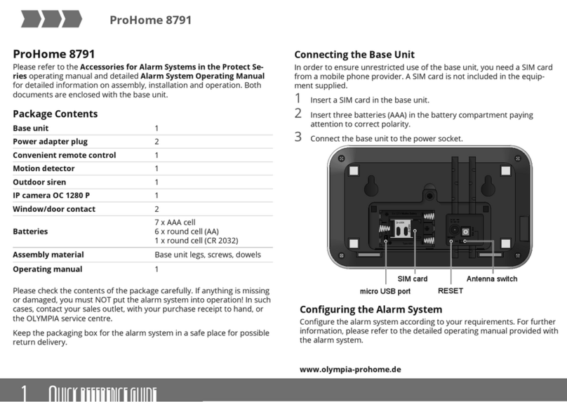
Olympia prohome 8791 User manual

Olympia
Olympia CI 200 User manual

Olympia
Olympia Protect 9XXX Series User manual

Olympia
Olympia Secure AS 602 User manual

Olympia
Olympia SECURE AS 302 User manual

Olympia
Olympia SECURE AS 605 User manual
Olympia
Olympia Protect 6 Series User manual
Olympia
Olympia Protect 9 Series User manual