Omnik Omniksol-15k-TL2 User manual

User Manual V1.2
User Manual
-Installation
-Operation
Omniksol-15k-TL2
Omniksol-17k-TL2
Omniksol-20k-TL2
Omnik New Energy Co.,Ltd.


1
Catalog
1. Notes on this manual...............................................................................................................................3
1.1 General notes..............................................................................................................................................3
1.2 Symbols Used ..............................................................................................................................................3
1.3 Target Group ...............................................................................................................................................4
2. Preparation................................................................................................................................................5
2.1 Safety Instructions.......................................................................................................................................5
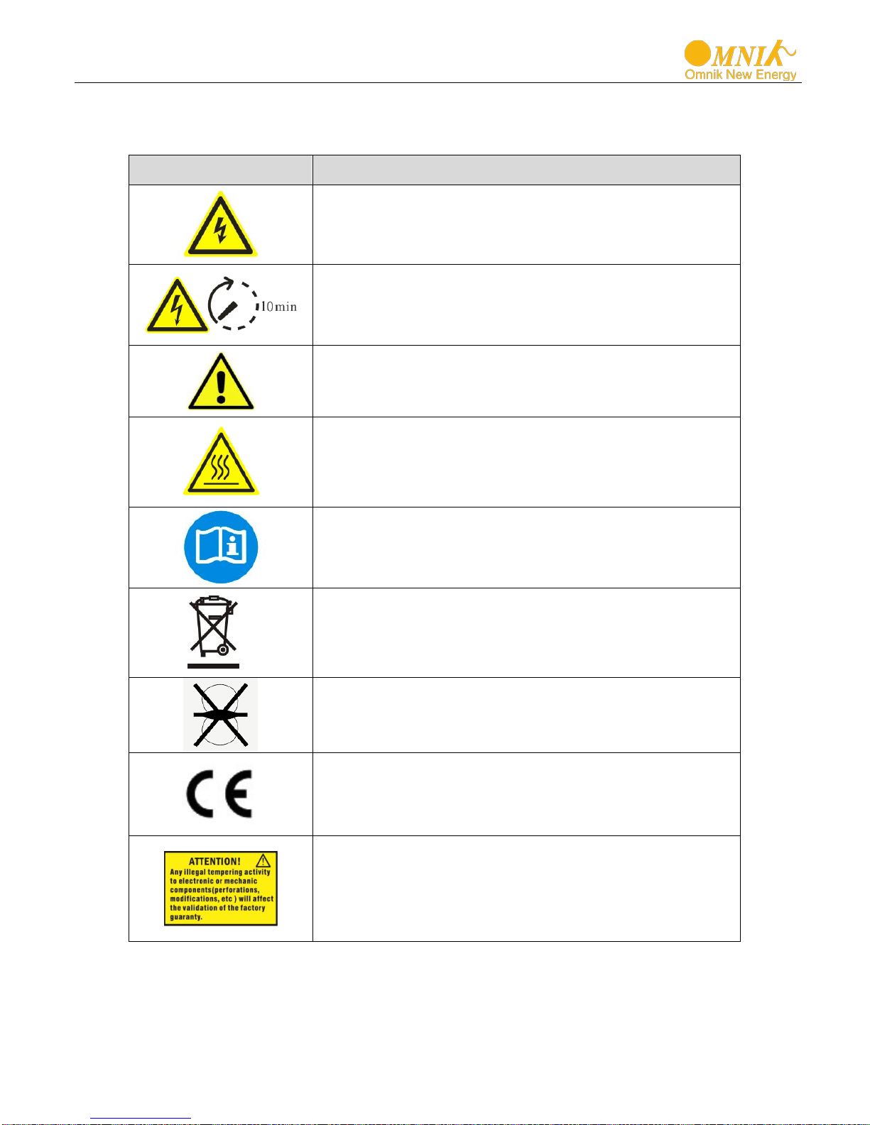
2.2 Explanations of Symbols on Inverter...........................................................................................................7
3. Product Information.................................................................................................................................8
3.1 Overview .....................................................................................................................................................8
3.2 Major Characteristics ..................................................................................................................................9
3.3 Technical Data .......................................................................................................................................... 10
4. Packing checklist ...................................................................................................................................12
4.1 Assembly parts ......................................................................................................................................... 12
4.2 Product Appearance................................................................................................................................. 13
4.3 Product Identification .............................................................................................................................. 14
4.4 Further Information ................................................................................................................................. 14
5. Installation...............................................................................................................................................15
5.1 Safety........................................................................................................................................................ 15
5.2 dimensions, weight .................................................................................................................................. 15
5.3 Mounting Instructions.............................................................................................................................. 16
5.4 Safety Clearance....................................................................................................................................... 17
5.5 Mounting Procedure ................................................................................................................................ 18
6. Electrical Connection.............................................................................................................................19
6.1 Safety........................................................................................................................................................ 19
6.2 DC Side Connection .................................................................................................................................. 20
6.3 AC side connection................................................................................................................................... 23
7. Display.....................................................................................................................................................25
7.1 LCD Panel.................................................................................................................................................. 25
7.2 Indicator ................................................................................................................................................... 26
7.3 Button....................................................................................................................................................... 26

2
7.4 Display ...................................................................................................................................................... 27
7.5 State Information ..................................................................................................................................... 42
8. Communication Setting.........................................................................................................................44
8.1 GPRS Card................................................................................................................................................. 44
8.2 Installation of communication card ......................................................................................................... 45
8.3 Register on monitoring website............................................................................................................... 48
8.4 Login monitoring System.......................................................................................................................... 52
8.5 WiFi card................................................................................................................................................... 57
8.6 Netwoek Settings ..................................................................................................................................... 58
8.7 RS485 card................................................................................................................................................ 68
9. Recycling and Disposal.........................................................................................................................69
10. Troubleshooting .....................................................................................................................................70
11. Abbreviation............................................................................................................................................72
12. Contact ....................................................................................................................................................73

3
1.Notes on this manual
1.1 General notes
The main purpose of this User’s Manual is to provide instructions and detailed
procedures for installing, operating, maintaining, and troubleshooting the following three
types of Omnik New Energy-Solar Inverters:
•Omniksol-15k-TL2
•Omniksol-17k-TL2
•Omniksol-20k-TL2
Please keep this user manual all time available in case of emergency.
1.2 Symbols Used
DANGER
DANGER indicates a hazardous situation which, if not
avoided, will result in death or serious injury.
WARNING
WARNING indicates a hazardous situation which, if not
avoided, can result in death or serious injury or moderate
injury.
CAUTION
CAUTION indicates a hazardous condition which, if not
avoided, can result in minor or moderate injury.
NOTICE
NOTICE indicates a situation that can result in property
damage, if not avoided.

4
1.3 Target Group
•Chapter 1, 2, 3, 4, 7, 8, 9, 10 ,11 and Chapter 12 are intended for anyone who is intended
to use Omnik Grid Tie Solar Inverter. Before any further action, the operators must first
read all safety regulations and be aware of the potential danger to operate high-voltage
devices. Operators must also have a complete understanding of this device’s features and
functions.
•Chapter 5 and Chapter 6 are only for qualified personnel who are intended to install or
uninstall the Omnik Grid Tie Solar Inverter. Installation must be suitable to the on-site
conditions and comply with local regulations and technical rules.
WARNING
Do not use this product unless it has been successfully installed
by
qualified personnel in accordance with the instructions in
Chapter 5, “Installation”.
NOTICE
Hereby qualified personnel means he/she has the valid license
from the local authority in:
•
Installing electrical equipment and PV power systems
(up to 1000 V).
•Applying all applicable installation codes.
•
Analyzing and reducing the hazards involved in
performing electrical work.
•
Selecting and using Personal Protective Equipment
(PPE).

5
2.Preparation
2.1 Safety Instructions
DANGER
DANGER due to electrical shock and high voltage
DO NOT touch the operating component of the inverter, it
might result in burning or death.
TO prevent risk of electric shock during installation and
maintenance, please make sure that all AC and DC terminals
are plugged out.
DO NOT stay close to the instruments while there is severe
weather conditions including storm, lighting etc.
WARNING
The installation,service ,
recycling and disposal of the
inverters must be performed by qualified personnel only in
compliance with national and local standards and
regulations. Please contact your dealer to get the
information of authorized repair facility for any maintenance
or repairmen.
Any unauthorized actions including modification of product
functionality of any form will affect the validation of warranty
service; Omnik may deny the obligation of warranty service
accordingly.

6
CAUTION
The PV inverter will become hot during operation; please
don’t touch the heat sink or peripheral surface during or
shortly after operation。
Risk of damage due to improper modifications.
Never modify or manipulate the inverter or other components
of the system.
NOTICE
Public utility only
The PV inverter designed to feed AC power directly into the
public utility power grid,do not connect AC output of the
device to any private AC equipment.

7
2.2 Explanations of Symbols on Inverter
Symbol Description
Dangerous electrical voltage
This device is directly connected to public grid, thus all
work to the inverter shall only be carried out by
qualified personnel.
DANGER to life due to high electrical voltage!
There might be residual currents in inverter because
of large capacitors. Wait 10 MINUTES
before you
remove the front lid.
NOTICE, danger!
This device directly connected with electricity
generators and public grid.
Danger of hot surface
The components inside the inverter will release a log
of heat during operation, DO NOT touch aluminum
housing during operating.
An error has occurred
Please go to Chapter 10 “Trouble Shooting” to remedy
the error.
This device SHALL NOT be disposed of in
residential waste
Please go to Chapter 9 “Recycling and Disposal” for
proper treatments.
Without Transformer
This inverter does not use transformer for the isolation
function.
CE Mark
Equipment with the CE mark fulfils the basic
requirements of the Guideline Governing Low-Voltage
and Electromagnetic Compatibility.
No unauthorized perforations or modifications
Any unauthorized perforations or modifications are
strictly forbidden, if any defect or damage
(device/person) is occurred, Omnik shall not take any
responsibility for it.

8
3.Product Information
3.1 Overview
•Industrial Layout
•Excellent Heat Elimination
•Effective Shield For DC/AC/Communication Connections

9
3.2 Major Characteristics
Omnik inverter has following characteristics which make Omnik inverter “High Efficiency,
High Reliability, High Cost Effective Ratio”
•Comply with multiple safety regulation of European, Asia Pacific and Oceania countries.
•Double MPPT Tracking, MPPT tracking accuracy up to 99.9%.
•Max. Efficiency 98.2%, European Efficiency 97.8%.
•Professional radiating design, protection Level IP65, work properly under severe
outdoor circumstances.
•Full solution of safety protection, DC switch integrated.
•Flexible input and output connections support RS485, Ethernet and USB
communication.
•Transformer less design and high power density, it is lighter and more convenient for
installation.

10
3.3 Technical Data
Type Omniksol-15k-TL2 Omniksol-17k-TL2 Omniksol-20k-TL2
Input (DC)
Max. PV Module Power 18000W 20400W 24000W
Max DC Voltage
1000V
1000V
1000V
Nominal DC Voltage 640V 640V 640V
Operating MPPT Voltage Range 250-800V 250-850V 250-850V
MPPT Voltage Range at Nominal
Power
360-800V 440-850V 480-850V
Start up DC Voltage 300V 300V 300V
Turn off DC Voltage
250V
250V
250V
Max. DC Current (A/B) 22A/22A 22A/22A 22A/22A
Max. Short Circuit Current for each
MPPT
25A/25A 25A/25A 25A/25A
Max. inverter back feed current to
the array [ A ] 0 A / 0 A 0 A / 0 A 0 A / 0 A
Number of MPP trackers 2 2 2
Number of DC Connection A:3/B:3 A:3/B:3 A:3/B:3
DC Connection Type Amphenol connector Amphenol connector Amphenol connector
Output (AC)
Nominal AC Power (cos phi = 1) 15000W 17000W 20000W
Nominal AC Voltage 3/N/PE; 220/380V
3/N/PE; 230/400V
3/N/PE; 240/415V
3/N/PE; 220/380V
3/N/PE; 230/400V
3/N/PE; 240/415V
3/N/PE; 220/380V
3/N/PE; 230/400V
3/N/PE; 240/415V
Nominal Grid Frequency 50Hz/60Hz 50Hz/60Hz 50Hz/60Hz
Max. AC Current 23.0A 26.0A 29.0A
Maximum output fault current 24.0A 27.0A 30.0A
Maximum output protection current
25.0A 28.0A 31.0A
Grid Voltage Range* 185-276V 185-276V 185-276V
Grid Frequency Range* 45-55Hz/55-65Hz 45-55Hz/55-65Hz 45-55Hz/55-65Hz
Power Factor 0.9i…1…0.9c 0.9i…1…0.9c 0.9i…1…0.9c
Total Harmonic Distortion (THD) <3% <3% <3%
Night time Power Consumption
<3W
<3W
<3W
AC Connection Type Terminal Blocks Terminal Blocks Terminal Blocks
Efficiency
Max. Efficiency 98.0% 98.0% 98.0%
Euro Efficiency 97.2% 97.2% 97.4%
MPPT Efficiency 99.9% 99.9% 99.9%
Safety and Protection
Protection Functions
Array ground insulation resistance monitoring Output over current protection
Residual current monitoring Surge protection
Array polarity reverse monitoring Output over/under voltage protection
Array over voltage protection
Output over/under frequency protection
Anti-island protection Over temperature protection
Array over current protection
Output short circuit protection
Protection Class I (According to IEC 62103)
Overvoltage Category PV II / Mains III (According to IEC 62109-1)

11
Type
Omniksol-15k-TL2
Omniksol-17k-TL2
Omniksol-20k-TL2
Reference Standard
Safety Standard
EN 62109-1/-2 , IEC 62109-1/-2
EMC Standard
EN 61000-6-1, EN 61000-6-2, EN 61000-6-3, EN 61000-6-4, EN 61000-3-11, EN
61000-3-12
Grid Standard VDE-AR-N-4105, VDE 0126-1-1, EN 50438, G59/3, IEC 62116, IEC 61727,
IEC61683, IEC 60068, NRS 097-2-1, NB/T 32004
Physical Structure
Dimensions (WxHxD) 558x560x182mm
Weight 45kg
Environmental Protection Rating IP 65 (According to IEC 60529)
Cooling Concept Fan cooling
Mounting Information Wall bracket
General Data
Operating Temperature Range
-20°C to +60°C(derating above 45℃)
Relative Humidity 0% to 100%
Max. Altitude (above sea level) 2000m
Noise Level <45dB
Environmental Category Rating
Outdoor, suitable to wet locations
Pollution class
II
UV resistance Yes
Isolation Type Transformerless
Display 5’ LCD Display
Data Communication Interfaces RS485 / WiFi / GPRS optional
Standard Warranty 5~25 years optional
*The AC voltage and frequency range may vary depending on specific country grid

12
4.Packing checklist
4.1 Assembly parts
After you receive the Omnik inverter, please check if there is any damage on the carton,
and then check the inside completeness for any visible external damage on the inverter
or any accessories. Contact your dealer if anything is damaged or missing. we will be
glad to assist you if required.
A
B
C
D
E
F
G
H
I
J
K
Object Quantity Description Object Quantity Description
A 1 Omnik inverter G 6 DC connector
B
1
Wall mounting bracket
H
5
Cord end terminal
C
1
user manual
I
4
Screw (M4X12)
D
4
Screw(ST6x50)
J
1
Connection diagram
E
4
Expansion tube
K
1
Removable front shield
F
1
AC cover

13
4.2 Product Appearance
•Front
Object Description
A Removable front cover
B LED Light (Three)
C Functional key(Four)
D LCD Display
•Bottom
Object Description
A DC switch
B Plug connectors for DC input.
C Communication interface
D Terminal for grid connection (AC output)
A
B
C
D
B
C
D
A

14
4.3 Product Identification
You can identify the inverter by the side nameplate. Information such as serial number
(SN.), type of the inverter, as well as inverter specifications are specified on the side
name plate. The name plate is on the middle part of the right side of the inverter
housing. And the following figure is the side name plate example as on Omniksol-20k-
TL2.
4.4 Further Information
If you have any further questions concerning the type of accessories or installation,
please check our website www.omnik-solar.com or contact our service hotline.

15
5.Installation
5.1 Safety
5.2 dimensions, weight
Model
weight
Dimension (L×W×D)
Omniksol-15K-TL2
45kg
558mm×560mm×182mm
Omniksol-17K-TL2
45kg
558mm×560mm×182mm
Omniksol-20K-TL2
45kg
558mm×560mm×182mm
DANGER
DANGER to life due to potential fire or electricity shock.
DO NOT install the inverter near any inflammable or
explosive items.
This inverter will be directly connected with HIGH
VOLTAGE power generation device, the installation must
be performed by qualified personnel only in compliance with
national and local standards and regulations.
NOTICE
NOTICE due to the inappropriate or the harmonized
installation environment may jeopardize the life span
of the inverter.
Installation directly expose under intensive sunshine is not
recommended.
The installation site MUST have good ventilation condition.

16
5.3 Mounting Instructions
•Omnik inverter is designed for indoors and outdoors installation
•Please mount the inverter in the direction as illustrated above
•Install the inverter in the vertical direction is recommended, with a max.15 degrees
backwards.
•For the convenience of checking the LCD display and possible maintenance
activities, please install the inverter at eye level.
•Make sure the wall you selected is strong enough to handle the screws and bear the
weight of the inverter
•Ensure the device is properly fixed to the wall
•It is not recommended that the inverter is exposed to the strong sunshine, because
the excess heating might lead to power reduction
•The ambient temperature of installation site should be between -25 °C and +60 °C
( between -13 °F and 140 °F )
•Make sure the ventilation of the installation spot, not sufficient ventilation may
reduce the performance of the electronic components inside the inverter and shorten
the life of the inverter

17
5.4 Safety Clearance
Observe the following minimum clearances to walls, other devices or objects to
guarantee sufficient heat dissipation and enough space for pulling the electronic solar
switch handle.
Direction Minimum clearance
Above 50 cm
Below 40 cm
Sides 30 cm
30cm
50cm
30cm
40cm

18
5.5 Mounting Procedure
1) Mark 4 positions of the drill holes on the wall according to the paper installation position
scale packed in the carton box.
2) First, according to the marks, drill 4 holes in the wall. Then, place four expansion tubes in
the holes using a rubber hammer. Next, wring 4 screws into the expansion tubes.
This manual suits for next models
2
Table of contents
Other Omnik Inverter manuals

Omnik
Omnik NS Series User manual

Omnik
Omnik SMP300 User manual

Omnik
Omnik Omniksol-3k-TL2 User manual

Omnik
Omnik Omniksol-10k-TL3 User manual

Omnik
Omnik Omniksol-1k-TL2 User manual

Omnik
Omnik Omniksol-2k-TL3-S User manual

Omnik
Omnik Omnikhyd Inverter 3KW User manual

Omnik
Omnik Omniksol-5KW-TH-TL3-NS User manual

Omnik
Omnik Omniksol-3k-TL User manual

Omnik
Omnik Omniksol-1k-TL-M User manual