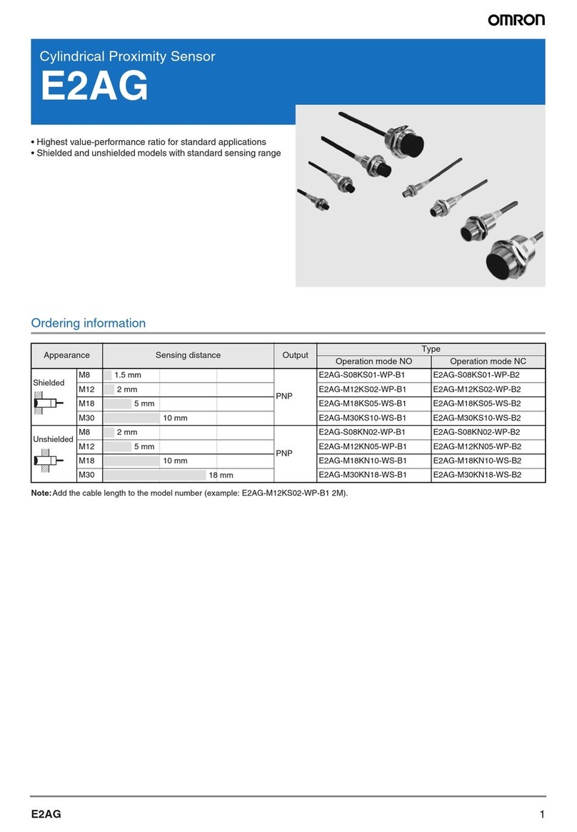
Omron F160 Vision Sensor User manual

Cat. No. Z147-E1-02
F160
Vision Sensor
Manual 3:
EXPERT MENU
OPERATION MANUAL

F160 Vision Sensor
Manual 3: Expert Menu Operation Manual
Revised June 2002

iv

v
Notice:
OMRON products are manufactured for use according to proper procedures by a qualified opera-
tor and only for the purposes described in this manual.
The following conventions are used to indicate and classify precautions in this manual. Always
heed the information provided with them. Failure to heed precautions can result in injury to people
or damage to property.
!DANGER Indicates an imminently hazardous situation which, if not avoided, will result in
death or serious injury.
!WARNING Indicates a potentially hazardous situation which, if not avoided, could result in
death or serious injury.
!Caution Indicates a potentially hazardous situation which, if not avoided, may result in
minor or moderate injury, or property damage.
OMRON Product References
All OMRON products are capitalized in this manual. The word “Unit” is also capitalized when it
refers to an OMRON product, regardless of whether or not it appears in the proper name of the
product.
Visual Aids
The following headings appear in the left column of the manual to help you locate different types
of information.
Note Indicates information of particular interest for efficient and convenient opera-
tion of the product.
1,2,3... 1. Indicates lists of one sort or another, such as procedures, checklists, etc.
Precaution Indicates information required to take full advantage of the functions and per-
formance of the product. Incorrect application methods may result in the loss
of damage or damage to the product. Read and follow all precautionary infor-
mation.
CHECK Indicates points that are important in using product functions or in application
procedures.
TwoCamera Indicates information required when using a 2-camera system.
SeeAlso Indicates where to find related information.
HELP Indicates information helpful in operation, such as the definition of terms.
OMRON, 2001
All rights reserved. No part of this publication may be reproduced, stored in a retrieval system, or trans-
mitted, in any form, or by any means, mechanical, electronic, photocopying, recording, or otherwise,
without the prior written permission of OMRON.
No patent liability is assumed with respect to the use of the information contained herein. Moreover,
because OMRON is constantly striving to improve its high-quality products, the information contained
in this manual is subject to change without notice. Every precaution has been taken in the preparation
of this manual. Nevertheless, OMRON assumes no responsibility for errors or omissions. Neither is
any liability assumed for damages resulting from the use of the information contained in this publica-
tion.

vii
TABLE OF CONTENTS
SECTION 1
Expert Menu Features . . . . . . . . . . . . . . . . . . . . . . . . . . . . . . . . . 1
1-1 Special Features of the Expert Menu. . . . . . . . . . . . . . . . . . . . . . . . . . . . . . . . . . 2
1-2 Types and Features of Measurement Methods . . . . . . . . . . . . . . . . . . . . . . . . . . 4
1-3 Compatibility with Conversational Menu . . . . . . . . . . . . . . . . . . . . . . . . . . . . . 14
1-4 Operational Flow . . . . . . . . . . . . . . . . . . . . . . . . . . . . . . . . . . . . . . . . . . . . . . . . 15
1-5 Menus . . . . . . . . . . . . . . . . . . . . . . . . . . . . . . . . . . . . . . . . . . . . . . . . . . . . . . . . 16
SECTION 2
Basic Operations . . . . . . . . . . . . . . . . . . . . . . . . . . . . . . . . . . . . . 21
2-1 Starting the F160 and Displaying Images . . . . . . . . . . . . . . . . . . . . . . . . . . . . . 22
2-2 Menu Operations . . . . . . . . . . . . . . . . . . . . . . . . . . . . . . . . . . . . . . . . . . . . . . . . 24
2-3 Two-camera Unit . . . . . . . . . . . . . . . . . . . . . . . . . . . . . . . . . . . . . . . . . . . . . . . . 32
2-4 Setting Inspection Conditions . . . . . . . . . . . . . . . . . . . . . . . . . . . . . . . . . . . . . . 35
2-5 Run Mode . . . . . . . . . . . . . . . . . . . . . . . . . . . . . . . . . . . . . . . . . . . . . . . . . . . . . 61
2-6 Saving Settings and Exiting the F160 . . . . . . . . . . . . . . . . . . . . . . . . . . . . . . . . 63
SECTION 3
Selecting and Setting Measurement Methods . . . . . . . . . . . . . 65
3-1 Area (Variable Box). . . . . . . . . . . . . . . . . . . . . . . . . . . . . . . . . . . . . . . . . . . . . . 68
3-2 Defect (Variable Box) . . . . . . . . . . . . . . . . . . . . . . . . . . . . . . . . . . . . . . . . . . . . 80
3-3 Gravity and Axis . . . . . . . . . . . . . . . . . . . . . . . . . . . . . . . . . . . . . . . . . . . . . . . . 90
3-4 OCR for 1 Character . . . . . . . . . . . . . . . . . . . . . . . . . . . . . . . . . . . . . . . . . . . . . 98
3-5 Classification . . . . . . . . . . . . . . . . . . . . . . . . . . . . . . . . . . . . . . . . . . . . . . . . . . 102
3-6 Surface Defects . . . . . . . . . . . . . . . . . . . . . . . . . . . . . . . . . . . . . . . . . . . . . . . . 112
3-7 Density Data . . . . . . . . . . . . . . . . . . . . . . . . . . . . . . . . . . . . . . . . . . . . . . . . . . 117
3-8 Edge Pitch . . . . . . . . . . . . . . . . . . . . . . . . . . . . . . . . . . . . . . . . . . . . . . . . . . . . 121
3-9 Edge Position. . . . . . . . . . . . . . . . . . . . . . . . . . . . . . . . . . . . . . . . . . . . . . . . . . 126
3-10 Edge Width . . . . . . . . . . . . . . . . . . . . . . . . . . . . . . . . . . . . . . . . . . . . . . . . . . . 133
3-11 Gray Search and Precise Search . . . . . . . . . . . . . . . . . . . . . . . . . . . . . . . . . . . 141
3-12 Flexible Search . . . . . . . . . . . . . . . . . . . . . . . . . . . . . . . . . . . . . . . . . . . . . . . . 148
3-13 Labeling. . . . . . . . . . . . . . . . . . . . . . . . . . . . . . . . . . . . . . . . . . . . . . . . . . . . . . 155
3-14 Relative Search . . . . . . . . . . . . . . . . . . . . . . . . . . . . . . . . . . . . . . . . . . . . . . . . 165
3-15 Rotation Search . . . . . . . . . . . . . . . . . . . . . . . . . . . . . . . . . . . . . . . . . . . . . . . . 173
SECTION 4
Detailed Setting Operations . . . . . . . . . . . . . . . . . . . . . . . . . . . 183
4-1 Calibration . . . . . . . . . . . . . . . . . . . . . . . . . . . . . . . . . . . . . . . . . . . . . . . . . . . . 185
4-2 Position Displacement Compensation. . . . . . . . . . . . . . . . . . . . . . . . . . . . . . . 197
4-3 Details on Expressions. . . . . . . . . . . . . . . . . . . . . . . . . . . . . . . . . . . . . . . . . . . 211

viii
TABLE OF CONTENTS
4-4 Display Details. . . . . . . . . . . . . . . . . . . . . . . . . . . . . . . . . . . . . . . . . . . . . . . . . 225
4-5 Display Strings. . . . . . . . . . . . . . . . . . . . . . . . . . . . . . . . . . . . . . . . . . . . . . . . . 227
4-6 Displaying Measurements . . . . . . . . . . . . . . . . . . . . . . . . . . . . . . . . . . . . . . . . 230
4-7 Displaying Judgements . . . . . . . . . . . . . . . . . . . . . . . . . . . . . . . . . . . . . . . . . . 233
4-8 Displaying Measurement Region Names . . . . . . . . . . . . . . . . . . . . . . . . . . . . 237
4-9 Displaying Measurement Time . . . . . . . . . . . . . . . . . . . . . . . . . . . . . . . . . . . . 238
4-10 Displaying Fixed Figures. . . . . . . . . . . . . . . . . . . . . . . . . . . . . . . . . . . . . . . . . 240
4-11 Displaying Results (Lines, Boxes, Circles, and Cursors) . . . . . . . . . . . . . . . . 242
4-12 Editing Measurement Regions and Position Compensation Regions . . . . . . . 245
SECTION 5
Other Functions . . . . . . . . . . . . . . . . . . . . . . . . . . . . . . . . . . . . 251
5-1 Changing Scenes and Scene Groups . . . . . . . . . . . . . . . . . . . . . . . . . . . . . . . . 252
5-2 Backing Up Data . . . . . . . . . . . . . . . . . . . . . . . . . . . . . . . . . . . . . . . . . . . . . . . 258
5-3 Checking Image Density Distribution: Line Brightness . . . . . . . . . . . . . . . . . 268
5-4 Checking I/O Status with External Devices . . . . . . . . . . . . . . . . . . . . . . . . . . 270
5-5 Memory Card Operations . . . . . . . . . . . . . . . . . . . . . . . . . . . . . . . . . . . . . . . . 273
SECTION 6
System Settings . . . . . . . . . . . . . . . . . . . . . . . . . . . . . . . . . . . . . 283
6-1 Entering System Mode . . . . . . . . . . . . . . . . . . . . . . . . . . . . . . . . . . . . . . . . . . 284
6-2 Camera Settings. . . . . . . . . . . . . . . . . . . . . . . . . . . . . . . . . . . . . . . . . . . . . . . . 284
6-3 Measurement Result Output Destinations. . . . . . . . . . . . . . . . . . . . . . . . . . . . 286
6-4 Screen Display and Monitor . . . . . . . . . . . . . . . . . . . . . . . . . . . . . . . . . . . . . . 290
6-5 Customizing Operations . . . . . . . . . . . . . . . . . . . . . . . . . . . . . . . . . . . . . . . . . 301
6-6 Setting Conditions for Saving Measurement Images . . . . . . . . . . . . . . . . . . . 310
6-7 Using BUSY Signals . . . . . . . . . . . . . . . . . . . . . . . . . . . . . . . . . . . . . . . . . . . . 314
6-8 Selecting Items to be Shown in Overall Judgements. . . . . . . . . . . . . . . . . . . . 315
6-9 Setting Startup Conditions. . . . . . . . . . . . . . . . . . . . . . . . . . . . . . . . . . . . . . . . 316
6-10 Setting the Calendar Date and Time (Date/Time) . . . . . . . . . . . . . . . . . . . . . . 317
6-11 Checking System Information. . . . . . . . . . . . . . . . . . . . . . . . . . . . . . . . . . . . . 317
6-12 Changing to Conversational Menus. . . . . . . . . . . . . . . . . . . . . . . . . . . . . . . . . 319
SECTION 7
Appendix . . . . . . . . . . . . . . . . . . . . . . . . . . . . . . . . . . . . . . . . . . 321
7-1 Terminology. . . . . . . . . . . . . . . . . . . . . . . . . . . . . . . . . . . . . . . . . . . . . . . . . . . 322
7-2 Character Codes. . . . . . . . . . . . . . . . . . . . . . . . . . . . . . . . . . . . . . . . . . . . . . . . 323
7-3 Troubleshooting. . . . . . . . . . . . . . . . . . . . . . . . . . . . . . . . . . . . . . . . . . . . . . . . 324
7-4 FAQ. . . . . . . . . . . . . . . . . . . . . . . . . . . . . . . . . . . . . . . . . . . . . . . . . . . . . . . . . 328


xi
About this Manual:
This manual describes setup procedures for the F160 Vision Sensor and it includes the sec-
tions described below.
This is one of four manuals used to operate the F160. Refer to the following table for the
contents of each manual.
Please read the above manuals carefully and be sure you understand the information pro-
vided before attempting to install or operate the F160.
Section 1 Expert Menu Features explains the features of the Expert Menu mode and its
compatibility with the Conversational Menu mode.
Section 2 Basic Operations describes the basic operations of the Expert Menus.
Section 3 Selecting and Setting Measurement Methods explains the measurement
methods provided by the Expert Menu (except for the gravity and area measurement
method, which is explained in Section 2).
Section 4 Detailed Setting Operations explains in more detail the basic setting operations
for the Expert Menus that were explained in Section 2.
Section 5 Other Functions describes additional functions such as changing the measure-
ment setup or backing up data.
Section 6 System Settings describes how to set conditions related to the system environ-
ment.
Section 7 Appendix provides information on terminology, character codes, troubleshooting,
and answers to FAQs.
Manual Contents Cat. No.
1:Setup Manual Provides information on system hardware and installa-
tion. Be sure to read this manual first. Z144-E1-02
2:Conversational
Menu Operation
Manual
Describes operation of the F160 using the Conversa-
tional Menus. The Conversational Menus enable the sim-
plest operation based on registered images of
acceptable and unacceptable products.
Z145-E1-02
3: Expert Menu
Operation Manual Describes operation of the F160 using the Expert Menus.
The Expert Menu enable application of all F160 capabili-
ties, including setting region images and criteria.
Z147-E1-02
4:Communications
Reference Man-
ual
Describes the communications settings and communica-
tions protocol used to transfer data through the parallel
interface or serial interface.
Z146-E1-02
!WARNING Failure to read and understand the information provided in this manual may result in per-
sonal injury or death, damage to the product, or product failure. Please read each section in
its entirety and be sure you understand the information provided in the section and related
sections before attempting any of the procedures or operations given.


1
SECTION 1
Expert Menu Features
This section explains the features of the Expert Menu mode and its compatibility with the Conversational Menu
mode.
1-1 Special Features of the Expert Menu. . . . . . . . . . . . . . . . . . . . . . . . . . . . . . . . 2
1-2 Types and Features of Measurement Methods . . . . . . . . . . . . . . . . . . . . . . . . 4
1-2-1 Measurement Methods . . . . . . . . . . . . . . . . . . . . . . . . . . . . . . . . . . . 4
1-2-2 Features of Measurement Methods. . . . . . . . . . . . . . . . . . . . . . . . . . 6
1-3 Compatibility with Conversational Menu . . . . . . . . . . . . . . . . . . . . . . . . . . . . 14
1-4 Operational Flow . . . . . . . . . . . . . . . . . . . . . . . . . . . . . . . . . . . . . . . . . . . . . . . 15
1-5 Menus . . . . . . . . . . . . . . . . . . . . . . . . . . . . . . . . . . . . . . . . . . . . . . . . . . . . . . . 16
1-5-1 Menus for One Camera . . . . . . . . . . . . . . . . . . . . . . . . . . . . . . . . . . . 16
1-5-2 Menus for Two Cameras . . . . . . . . . . . . . . . . . . . . . . . . . . . . . . . . . . 19

2
Special Features of the Expert Menu Section 1-1
1-1 Special Features of the Expert Menu
Seventeen Measurement Methods for Various Detection Needs
Select the measurement method according to application.
Complicated detection is also possible, by combining multiple measurement
methods and with detailed settings.
• Area (var. box)
• Defect (var. box)
• Gravity and area (See note.)
• Gravity and axis (See note.)
• OCR for 1 chara
• Classification
• Defect
• Density data
• Edge pitch
• Edge position (See note.)
• Edge width
• Gray search (See note.)
• Precise search
• Flexible search
• Labeling (See note.)
• Relative search
• Rotation search (See note.)
Note Position displacement compensation is also supported for these
measurement methods.
Two-camera Operation
If two Cameras are connected, detection can be performed from two directions
and the field of vision can be split in two.
SeeAlso Refer to page 32.
Smooth Setup Changes
Scenes can be used to change between up to 32 types of measurement set-
ups. Simply change the scene to change to a different measurement setup. A
128-MB Memory Card can be used to store up to 1,024 scenes.
SeeAlso Refer to page 252.
Flexible Settings for Data Output to External Devices
In addition to simply outputting measurement results, expressions or arith-
metic functions can be set to output special data, such as the distance
between two regions or the maximum measurement value.

3
Special Features of the Expert Menu Section 1-1
SeeAlso Refer to page 211.
Up to 35 Screens of NG Measurement Object Images
Past defects can be checked on screen.
Saved images are cleared when the power is turned OFF.
Images can be saved as bitmaps, which are useful when creating reports or
operating procedures.
SeeAlso Refer to page 310.
Customizing
Customize Screens
SeeAlso Refer to page 225.
• Messages displayed on screen can be changed for easier comprehension
of the measurement and its purpose.
0.LABEL MON
Scene names can be changed according to the
measurement details (See note.).
Customize
Measurement region names can be changed
to suit the measurement. (See note.)
Individual region
0.Presence
Judge : OK
Correleation : 92
Position X : 200.000
Position Y : 140.000
0.Scn 0 OK 67ms
Freeze
OK 67ms
Freeze
MON
Individual region
0.Gray search
Judge : OK
Correlation : 92
Position X : 200.000
Position Y : 140.000

4
Types and Features of Measurement Methods Section 1-2
• The display method for the measurement results can also be changed as
required.
Customize Operations
SeeAlso Refer to page 301.
• Access can be limited by using a password to prevent incorrect operation.
• Frequently-used operations can be allocated to the Console Keys, allow-
ing faster, one-touch operation.
1-2Types and Features of Measurement Methods
Various measurement methods can be selected according to the application
and measurement details. The possible applications for some measurement
methods is much wider depending on the way the method is used. In this sec-
tion, however, only the most typical applications are described.
1-2-1 Measurement Methods
The Expert Menu has 17 types of measurement.
• Area (variable box)
• Defect (variable box)
• Gravity and area
• Gravity and axis
• OCR for 1 character
• Classification
• Defect
• Density data
• Edge pitch
• Edge position
• Edge width
• Gray search
• Precise search
• Flexible search
• Labeling
• Relative search
• Rotation search
Freeze
OK 67ms
0.LABEL MON
Fixed figures, such as lines, can always be displayed.
(Useful as a guide to the position of the measurement object.)
Figures can be displayed at
detection position
A display cursor is displayed
at the label detection position
in this example.
Difference from standard
: 20
Measurement value displayed in suitable position.
Use suitable characters.

5
Types and Features of Measurement Methods Section 1-2
Guide to Selecting Measurement Methods
Measurement target Example
measurement
methods
Typical application
examples
Size (area) Gravity and area
Area (var. box) Detect presence (expiration
dates, parts, etc.)
Detect adhesive coatings.
Detect caulking of metal parts.
Position Center of gravity coor-
dinates (Processing
time: Short)
Gravity and area Robot handling.
Position PCBs.
Any particular coordi-
nates (Processing
time: Long)
Gray search
Precise search
Flexible search
Robot handling.
Position PCBs.
Dimensions Edge position
Edge width Detect dimensions of molded
products (e.g., width of tiles or
paper, length of bolts, internal
diameter of PCB holes.)
Position displacement Relative search Detect position displacement
(printing, labels, etc.)
Fluid volume checks.
Detect insufficient tightening of
caps.
Shape (correlation) Gray search
Precise search
Flexible search
Detect foreign items in pack-
ages.
Discriminate between direc-
tions (parts, marks, etc.)
Angle Gravity and axis
Rotation search Detect rotary switch position
(angle).
Number Edge pitch
Labeling Detect number of pins (IC,
connectors, etc.)
Detect detached wiring cables.
Detect number of gears.
Defect Defect
Defect (var. box) Detect marks on sheeting.
Detect defects and burrs on
molded products.
Check pinholes.
Detect impurities in fluids.
Examine exterior of chip parts.
Brightness Density data Detect foreign objects.
Detect presence.
Characters OCR for 1 character Read lot number.
Classification Classification Discriminate between grades,
e.g., on fruit boxes.
(X,Y)
(X,Y)
1234

6
Types and Features of Measurement Methods Section 1-2
1-2-2 Features of Measurement Methods
Area (Var. Box) Use an area (variable box) measurement to adjust the measurement region (a
box) for measurement objects with varying sizes or positions and find their size
and center of gravity.
The upper, lower, left, and right edges of the measurement object are found.
With the edges detected, the F160 can determine where the measurement
object is. Even if the size and position of the measurement object changes, the
F160 can move the measurement region appropriately.
Once the edges have been found, the image is converted to a binary image
and the area and center of gravity of the measurement region are found.
SeeAlso Refer to page 7 for information on Gravity and Area.
Defect (Var. Box) Use a defect (variable box) measurement to adjust the measurement region (a
box) for measurement objects with varying sizes or positions and find defects.
The edges are found in the same way as for Area (var. box) and the measure-
ment region is moved as required.
Once the edges have been found, the defects inside the measurement region
are detected.
SeeAlso Refer to page 9 for information on Defect.
Gravity and Area Use a gravity and area measurement to find the size and position (center of
gravity) of a measurement object.
Measurement region
Upper edge
Lower edge
Left edge Right edge
Measurement region
Measurement region

7
Types and Features of Measurement Methods Section 1-2
The image read by the Camera is a 256-gradation image. This is converted to
a binary image made up of black and white pixels. The F160 focusses on the
white areas only and performs measurement.
Area The area is the number of white pixels in the measurement region.
Center of
Gravity The center of gravity is the center of the area of white pixel. When the white
pixel area of the region forms a square, the center of gravity is the intersection
of the lines from diagonal corners.
HELP Refer to page 322 for information on the center of gravity.
CHECK When a gravity and area measurement is used, an object will receive an OK
judgement if the number of white pixels is the same as the OK setting, even if
the shape is different. To distinguish shapes, use a gray search, precise
search, or flexible search.
CHECK Use an area (var. box) measurement for measurement objects with varying
measurement region sizes or positions.
Gravity and Axis Use a gravity and axis measurement to find the angle of a measurement
object.
This measurement method also calculates the axis angle, in addition to the
binary center of gravity and area calculations described previously.
Axis Angle The axis angle is the angle of the major axis of an ellipse that is diagrammati-
cally equivalent to the area occupied by the white pixels.
CHECK More processing time is required to calculate the axis angle. To simply find the
area and center of gravity, use a gravity and area measurement.
Measurement region
No. of white pixels = area
Center of gravity of the white pixels
Measurement region
Axis angle
No. of white pixels = area
Center of gravity of white pixels
q

8
Types and Features of Measurement Methods Section 1-2
OCR for 1 Character
Use an OCR for 1 character measurement to recognize alphanumeric charac-
ters and special symbols. The F160 provides a dictionary, so no models need
to be registered.
The F160 recognizes two candidates, 1st candidate and 2nd candidate, from
the dictionary, that are most similar to the character image in the measurement
region.
If the density deviation is not greater than the set value, the image is recog-
nized as having no pattern (no detectable marks).
CHECK An expression can be set to output the character code of the recognized char-
acter to an external device. The output when no pattern is detected is the
underscore (_) character code.
Classification Use a classification measurement to classify products, for example, on a line
for a variety of products.
A model is registered beforehand that will serve as the classification reference.
Up to 36 types of models can be registered to index numbers 0 to 35.
When the printing quality or shape of the model is inconsistent, register multi-
ple models to the same index number. Up to 5 models can be registered to the
same index number.
CHECK When multiple models are registered to the same index number, the F160
automatically creates auxiliary models between the models that are regis-
tered. If the auxiliary models are added to the registered models when
searches are performed, stable searches are possible even if there are varia-
tions between the registered models. You can select whether or not to use
auxiliary models in searches. Refer to page 323 for information on auxiliary
models.
Measurement region
5
1st candidate: 5
2nd candidate: S
A
C
B
Model registraion
A
B
C
0
1
2
3
4
5
6
7
Index 0 to index 35
A
B
C
A registered to 0 C registered to 2B registered to 1
Model (Up to 5 models can be registered)
SFT+- ¯:Switch

9
Types and Features of Measurement Methods Section 1-2
The F160 outputs the number of the index for the model that most resembles
the image. If there is no model that resembles the image, NG is output. Once
that data has been received by the external device, the product can be classi-
fied at the next processing stage.
CHECK Expressions must be set to output data to an external device.
Defect Use a defect measurement to detect defects in unpatterned measurement
objects.
This method checks for surface defects by measuring variations in density.
The shape of the measurement region can be chosen from arc, box, circumfer-
ence, or line.
CHECK The measurement object cannot be measured correctly if there is a pattern or
marks on the object. This method uses variations in density, so if there is a
pattern or marks within the measurement region it will be detected as a defect.
To measure areas with patterns or marks, use a gray search, precise search,
or flexible search. Refer to page 11.
CHECK Use a defect (variable box) measurement for measurement objects with vary-
ing measurement region sizes or positions.
Density Data Use a density data measurement to detect the presence of a measurement
object.
Example: Detecting the Presence of Electronic Parts
Set two measurement regions, one for the part location and one for the back-
ground. The density average of each is measured and the difference is used to
check if the part is present. If the part is present, the density difference with
the background will be large. If the part is not present, the density difference
will be small.
0
Camera
12
Searches for the model with the highest correlation.
Outputs the index number.
A
B
C
Measurement region
Defect
Other manuals for F160 Vision Sensor
5
Table of contents
Other Omron Accessories manuals

Omron
Omron FZ3 Series User manual

Omron
Omron E3F User manual

Omron
Omron V680-HAM91 User manual

Omron
Omron F10 User manual

Omron
Omron ZFX-C10 COMMUNICATION User manual

Omron
Omron E3X-DAC-S Series User manual

Omron
Omron E3X-DA-SE-S User manual

Omron
Omron E3Z-LT User manual

Omron
Omron E2 ELITE User manual

Omron
Omron FQ-AC Series User manual

Omron
Omron E2KQ-X User manual

Omron
Omron Z510 User manual

Omron
Omron E3X-MDA11 User manual

Omron
Omron FZ2-30 10 Series User manual

Omron
Omron TL-T User manual

Omron
Omron ZG - User manual

Omron
Omron EQUO Series User guide

Omron
Omron ZS Operating manual

Omron
Omron ZN-KMX21 Series User manual

Omron
Omron E32 - User manual