Omron F250-C50 C55 - SETUP 09-2001 User manual

)9LVLRQ6HQVRU
)&&
0DQXDO6HWXS0DQXDO
3URGXFHG6HSWHPEHU

iv

v
Notice:
OMRON products are manufactured for use according to proper procedures by a qualified opera-
tor and only for the purposes described in this manual.
The following conventions are used to indicate and classify precautions in this manual. Always
heed the information provided with them. Failure to heed precautions can result in injury to people
or damage to property.
!DANGER Indicates an imminently hazardous situation which, if not avoided, will result in
death or serious injury.
!WARNING Indicates a potentially hazardous situation which, if not avoided, could result in
death or serious injury.
!Caution Indicates a potentially hazardous situation which, if not avoided, may result in
minor or moderate injury, or property damage.
OMRON Product References
All OMRON products are capitalized in this manual. The word “Unit” is also capitalized when it
refers to an OMRON product, regardless of whether or not it appears in the proper name of the
product.
Visual Aids
The following headings appear in the left column of the manual to help you locate different types
of information.
Note Indicates information of particular interest for efficient and convenient opera-
tion of the product.
1,2,3... ,QGLFDWHVOLVWVRIRQHVRUWRUDQRWKHUVXFKDVSURFHGXUHVFKHFNOLVWVHWF
Precaution Indicates information required to take full advantage of the functions and per-
formance of the product. Incorrect application methods may result in the loss
of damage or damage to the product. Read and follow all precautionary infor-
mation.
CHECK Indicates points that are important in using product functions or in application
procedures.
TwoCamera Indicates information required when using a 2-camera system.
SeeAlso Indicates where to find related information.
HELP Indicates information helpful in operation, such as the definition of terms.
¸OMRON, 2001
All rights reserved. No part of this publication may be reproduced, stored in a retrieval system, or trans-
mitted, in any form, or by any means, mechanical, electronic, photocopying, recording, or otherwise,
without the prior written permission of OMRON.
No patent liability is assumed with respect to the use of the information contained herein. Moreover,
because OMRON is constantly striving to improve its high-quality products, the information contained
in this manual is subject to change without notice. Every precaution has been taken in the preparation
of this manual. Nevertheless, OMRON assumes no responsibility for errors or omissions. Neither is
any liability assumed for damages resulting from the use of the information contained in this publica-
tion.


vii
TABLE OF CONTENTS
PRECAUTIONS . . . . . . . . . . . . . . . . . . . . . . . . . . . . . . . . . . . . . xi
1 Special or Critical Applications. . . . . . . . . . . . . . . . . . . . . . . . . . . . . . . . . . . . . xii
2 General Safety Precautions . . . . . . . . . . . . . . . . . . . . . . . . . . . . . . . . . . . . . . . . xii
3 Regulations and Standards. . . . . . . . . . . . . . . . . . . . . . . . . . . . . . . . . . . . . . . . .xiii
SECTION 1
Introduction. . . . . . . . . . . . . . . . . . . . . . . . . . . . . . . . . . . . . . . . . . 1
1-1 Installation Precautions . . . . . . . . . . . . . . . . . . . . . . . . . . . . . . . . . . . . . . . . . . . . 2
1-2 Confirming Package Contents. . . . . . . . . . . . . . . . . . . . . . . . . . . . . . . . . . . . . . . 6
1-3 Product Availability. . . . . . . . . . . . . . . . . . . . . . . . . . . . . . . . . . . . . . . . . . . . . . . 6
SECTION 2
Special Features, Installation, and Connections . . . . . . . . . . . . 7
2-1 Special Features. . . . . . . . . . . . . . . . . . . . . . . . . . . . . . . . . . . . . . . . . . . . . . . . . . 8
2-2 Basic System Configuration . . . . . . . . . . . . . . . . . . . . . . . . . . . . . . . . . . . . . . . 12
2-3 Component Names and Functions. . . . . . . . . . . . . . . . . . . . . . . . . . . . . . . . . . . 14
2-4 Mounting the Controller . . . . . . . . . . . . . . . . . . . . . . . . . . . . . . . . . . . . . . . . . . 15
2-5 Connecting Peripheral Devices . . . . . . . . . . . . . . . . . . . . . . . . . . . . . . . . . . . . . 17
2-6 Power Supply and Ground. . . . . . . . . . . . . . . . . . . . . . . . . . . . . . . . . . . . . . . . . 19
SECTION 3
Lenses, Lighting, and Memory Cards. . . . . . . . . . . . . . . . . . . . 21
3-1 CCTV Lenses. . . . . . . . . . . . . . . . . . . . . . . . . . . . . . . . . . . . . . . . . . . . . . . . . . . 22
3-2 Lighting . . . . . . . . . . . . . . . . . . . . . . . . . . . . . . . . . . . . . . . . . . . . . . . . . . . . . . . 25
3-3 Memory Cards. . . . . . . . . . . . . . . . . . . . . . . . . . . . . . . . . . . . . . . . . . . . . . . . . . 27
SECTION 4
Connecting External Devices. . . . . . . . . . . . . . . . . . . . . . . . . . . 29
4-1 Connecting through the Parallel Interface. . . . . . . . . . . . . . . . . . . . . . . . . . . . . 30
4-2 Connecting through the Serial Interface . . . . . . . . . . . . . . . . . . . . . . . . . . . . . . 37
SECTION 5
Troubleshooting and Maintenance . . . . . . . . . . . . . . . . . . . . . . 43
5-1 Troubleshooting. . . . . . . . . . . . . . . . . . . . . . . . . . . . . . . . . . . . . . . . . . . . . . . . . 44
5-2 Maintenance. . . . . . . . . . . . . . . . . . . . . . . . . . . . . . . . . . . . . . . . . . . . . . . . . . . . 46
5-3 Regular Inspections . . . . . . . . . . . . . . . . . . . . . . . . . . . . . . . . . . . . . . . . . . . . . . 49
5-4 Specifications. . . . . . . . . . . . . . . . . . . . . . . . . . . . . . . . . . . . . . . . . . . . . . . . . . . 50
5-5 F200/F300 Camera Parameters . . . . . . . . . . . . . . . . . . . . . . . . . . . . . . . . . . . . . 68
5-6 Connecting a Strobe Device . . . . . . . . . . . . . . . . . . . . . . . . . . . . . . . . . . . . . . . 70
Index. . . . . . . . . . . . . . . . . . . . . . . . . . . . . . . . . . . . . . . . . . . . . . . 71
Revision History . . . . . . . . . . . . . . . . . . . . . . . . . . . . . . . . . . . . . 73


ix
$ERXWWKLV0DQXDO
This manual describes the hardware for the F250 Vision Sensor and how to install the com-
ponents, and it includes the sections described below. This is one of two manuals used to
operate the F250. Refer to the following table for the contents of each manual.
Please read the above manuals carefully and be sure you understand the information pro-
vided before attempting to install or operate the F250.
Section 1 Introduction describes the precautions that must be taken when installing and
operating the F250 Vision Sensor.
Section 2 Special Features, Installation, and Connections shows a basic F250 system
configuration and explains how to install the F250 and connect it to a power supply and
peripheral devices.
Section 3 Lenses, Lighting, and Memory Cards describes how to select and use these
components most effectively.
Section 4 Connecting External Devices describes how to connect external devices
through a parallel interface (the parallel connectors) or serial interface (the RS-232C/RS-
422 connector or Ethernet connector).
Section 5 Troubleshooting and Maintenance provides tables to help identify and correct
hardware errors that may occur with the F250 as well as information on maintenance and
periodic inspections.
Manual Contents Cat. No.
1:Setup Manual Provides information on system hardware and installa-
tion. Be sure to read this manual first. SCHB-736A
2:OperationManual
(on CD-ROM) The Operation Manual CD-ROM is packed with the
F250-UME Application Software. This manual explains
basic operations such as installing the Application Soft-
ware, setting up inspection processes, and communicat-
ing with external devices.
Z153-E1-01
!WARNING Failure to read and understand the information provided in this manual may result in per-
sonal injury or death, damage to the product, or product failure. Please read each section in
its entirety and be sure you understand the information provided in the section and related
sections before attempting any of the procedures or operations given.


xi
PRECAUTIONS
This section provides general precautions for using the F250 Vision Sensor.
The information contained in this section is important for the safe and reliable application of the F250
Vision Sensor. You must read this section and understand the information contained before attempting to
set up or operate an F250 Vision Sensor.
1 Special or Critical Applications. . . . . . . . . . . . . . . . . . . . . . . . . . . . . . . . . . . . xii
2 General Safety Precautions . . . . . . . . . . . . . . . . . . . . . . . . . . . . . . . . . . . . . . . xii
3 Regulations and Standards. . . . . . . . . . . . . . . . . . . . . . . . . . . . . . . . . . . . . . . . xiii

xii
Special or Critical Applications 1
1 Special or Critical Applications
When the F250 will be used in one of the conditions or applications listed
below, allow extra safety margins in ratings and functions, add extra safety fea-
tures such as fail-safe systems, and consult your OMRON representative.
• Operating conditions or environments which are not described in the
manual
• Nuclear power control systems, railroad systems, aviation systems, vehi-
cles, combustion systems, medical equipment, amusement equipment, or
safety equipment
• Other systems, machines, and equipment that may have a serious influ-
ence on lives and property and require extra safety features
2 General Safety Precautions
Battery Precautions
!WARNING Do not disassemble the F250, apply pressure to the F250 that would deform
its shape, or incinerate the F250. A lithium battery is built into the F250 and it
may combust, explode, or burn if not treated properly.
!WARNING Do not short circuit, attempt to charge, disassemble, apply pressure that would
deform, or incinerate the lithium battery. The lithium battery may start a fire,
explode, or burn if not treated properly.
Installation Environment Precautions
!Caution Do not use the F250 in environments with flammable or explosive gases.
!Caution Install the F250 away from high-voltage devices and moving machinery to
allow safe access during operation and maintenance.
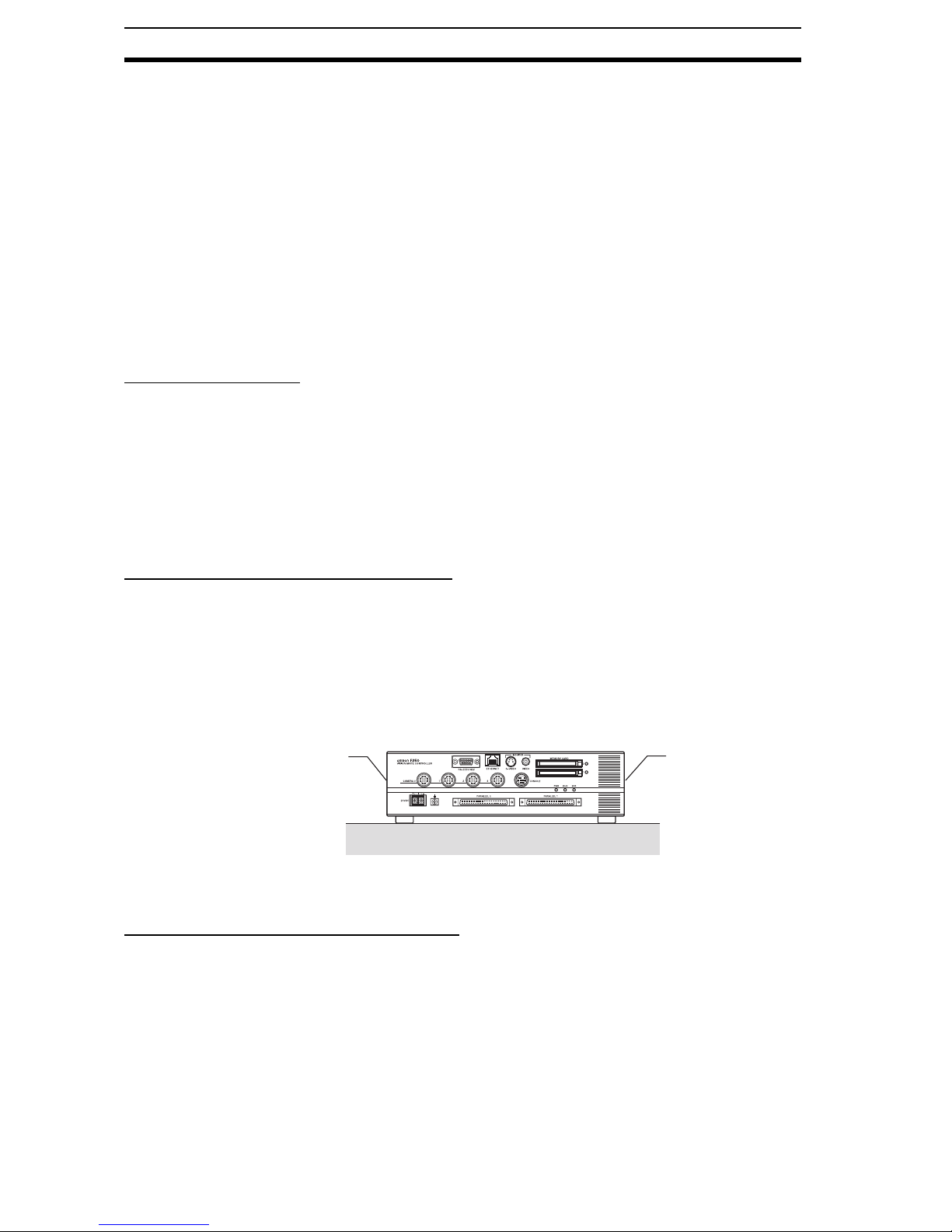
!Caution Install the F250 so that air can flow freely through its cooling vents. If the vents
are blocked, heat will build up in the Controller and may cause burns.
!Caution Be sure to securely tighten the screws when mounting the F250.
Power Supply and Wiring Precautions
!Caution Use the F250 with the power supply voltages specified in this manual.
!Caution Use the wire and crimp terminals of the proper sizes as specified in this man-
ual. Do not connect the power supply wires by just twisting stranded wire and
connecting directly to the terminals.
!Caution Use a DC power supply with countermeasures against high-voltage spikes
(safe extra low-voltage circuits on the secondary side).
Intake vent Exhaust vent

xiii
Regulations and Standards 3
Note 1. Keep the power supply wires as short as possible (Max. 10 m).
2. Ground the F250’s ground terminal to less than 100 W.
3. Use a grounding point as close as possible to the F250 and keep the
ground line as short as possible.
4. Wire the F250 tothe ground with a separate ground wire. To avoid ground-
ing problems, do not share the ground wiring with any other devices or
ground the F250 to the building’s steel framing/plumbing.
Other Precautions
!Caution Do not attempt to dismantle, repair, or modify the F250.
!Caution Do not touch fluorescent or halogen lights while the power is ON or immedi-
ately after the power is turned OFF. These lights get very hot and can cause
burns.
!Caution If you suspect an error or malfunction, stop using the F250 immediately, turn
OFF the power supply, and consult your OMRON representative.
Note Dispose of the F250 as industrial waste.
3 Regulations and Standards
The F250 complies with the EC Directive and EN standard below.
1. EC Directives
EMC Directive: No. 89/336/EEC
2. EN Standards (European Standards)
EN 61326: 1997/Annex A+A1: 1998 (EMI: Class A)


1
SECTION 1
Introduction
This section describes the precautions that must be taken when installing and operating the F250 Vision Sensor.
1-1 Installation Precautions. . . . . . . . . . . . . . . . . . . . . . . . . . . . . . . . . . . . . . . . . . 2
1-1-1 Controller Installation. . . . . . . . . . . . . . . . . . . . . . . . . . . . . . . . . . . . 2
1-1-2 Component Installation and Handling . . . . . . . . . . . . . . . . . . . . . . . 4
1-2 Confirming Package Contents . . . . . . . . . . . . . . . . . . . . . . . . . . . . . . . . . . . . 6
1-3 Product Availability . . . . . . . . . . . . . . . . . . . . . . . . . . . . . . . . . . . . . . . . . . . . 6

2
Installation Precautions Section 1-1
1-1 Installation Precautions
The F250 is highly reliable and resistant to most environmental factors. The
following guidelines, however, must be followed to ensure reliability and opti-
mum use of the F250.
!Caution Read the Precautions section before proceeding with installation or operation.
1-1-1 Controller Installation
Installation Site Do not install the F250 in locations subject to the following conditions:
1,2,3... 1. Ambient temperatures outside of the 0 to 50C (32 to 122F) range
2. Rapid temperature fluctuations (likely to cause condensation)
3. Relative humidities outside of the 35% to 85% range
4. Presence of corrosive or flammable gases
5. Presence of dust, salt, or iron particles
6. Direct vibration or shock
7. Direct sunlight
8. Water, oil, or chemical fumes or spray
Orientation of Controller
To improve heat dissipation, install the Controller in the following orientation
only. For proper air flow, provide at least 20 mm of clearance above the Con-
troller and at least 50 mm of clearance on both sides.
• Horizontal Installation
Do not install the Controller upside down as shown in the following dia-
gram.
CORRECT
INCORRECT

3
Installation Precautions Section 1-1
• Vertical Installation
The Controller can be installed vertically with the air intake at the bottom
and exhaust at the top. For proper air flow, provide at least 20 mm of clear-
ance at the top of the Controller and at least 50 mm of clearance on both
sides (the intake and exhaust sides).
Ambient Temperature
1,2,3... 1. For proper air flow, maintain a minimum clearance of 20 mm at the top of
the F250 and at least 50 mm of clearance at the sides where the cooling
air intake and exhaust are located.
2. Do not install the F250 immediately above significant heat sources, such
as heaters, transformers, or large-capacity resistors.
3. Do not let the ambient operating temperature exceed 50C (122F).
4. Provide a forced-air fan cooling or air conditioning if the ambient tempera-
ture is near 50C (122F) so that the ambient temperature never exceeds
50C (122F).
INCORRECT
CORRECT
Exhaust
Intake
Intake
Exhaust
Louver
Control panel
F250

4
Installation Precautions Section 1-1
Noise Resistance Use the following measures to help increase noise resistance.
1,2,3... 1. Do not install the F250 in a cabinet containing high-voltage equipment.
2. Do not install the F250 within 200 mm of power cables.
1-1-2 Component Installation and Handling
OMRON ComponentsUse a Camera, Camera Cable, and Console designed specifically for the
F250.
Connecting Cables Always turn OFF the F250’s power before connecting or disconnecting a cam-
era or cable.
Handling the CameraThe Camera’s case is connected to the 0V line in the internal circuits. Observe
the following precautions to prevent noise interference.
1,2,3... 1. Do not ground the Camera.
2. Do not remove the base attached to the Camera.
3. Do not remove the ferrite core attached to the F150-VS or F160-VSR@@
Camera Cable.
Securing the Video Monitor (When Using the Recommended F150-M09)
Observe the following precautions to prevent noise interference, because the
video monitor case is connected to the 0V line in the internal circuits.
1,2,3... 1. Do not ground the video monitor.
2. Do not ground the metallic part of the connector.
3. Secure the video monitor with plastic screws if it is being mounted to a me-
tallic surface.
Touching Signal Lines
To prevent damage from static electricity, use a wrist strap or another device
for preventing electrostatic discharges when touching terminals or signal lines
in connectors.
Handling the Memory Card
• To prevent damage from static electricity, do not touch the Memory Card
directly while it is installed in the F250.
• To remove a Memory Card, turn OFF the power supply to the Card (using
the menu command) or turn OFF the F250. Press the eject button to eject
the Card. The Memory Card or the F250 itself may be damaged if a Mem-
ory Card is removed while power is being supplied.
Note F250-UME Precautions
It will not be possible to start the Setup Menu if you change the contents of the
Memory Card after installing it in a personal computer or other device. Never
200 mm min.
Power lines
F250 200 mm min.

5
Installation Precautions Section 1-1
change the contents of the Card with operations such as the following:
• Changing file names
• Moving or deleting files
• Overwriting data
• Formatting
Turning OFF the Power
Do not turn OFF the power while a message is being displayed indicating that
processing is being performed. Data in memory will be corrupted, and the
F250 may not operate correctly the next time it is started.
Using the RESET Signal
Do not use the RESET input immediately after power is turned ON. When
using the RESET input to synchronize startup timing, wait at least 1 second
after the F250's power supply is turned ON before turning ON the RESET sig-
nal.
Replacing the Battery
The F250 is equipped with a battery that backs up the clock. When the battery
is low, the message “BATTERY LOW” will be displayed on the monitor at star-
tup. The battery must be replaced when this message is displayed. Return the
F250 to your OMRON dealer for service. (The battery is not user-serviceable.)
The battery will last approximately 7 years.
Saving data.
---- ---ms
0.Scn 0 MON

6
Confirming Package Contents Section 1-2
1-2 Confirming Package Contents
Check the contents of the package as soon as you receive the F250. It is
extremely rare for components to be missing, but contact the nearest OMRON
representative if any of the following items are missing.
1,2,3... 1. F250 Vision Mate Controller Qty.: 1
2. Ferrite core for F150-KP Console or F160-KP Console Qty: 1
Ferrite core for F150-VM Monitor Cable Qty: 1
3. Setup Manual (this manual) Qty.: 1
CHECK The F250 Vision Sensor Manual 2: Operation Manual (on CD-ROM) is packed
with the F250-UME Application Software.
1-3 Product Availability
Some of the products listed may not be available in some countries. Please
contact your nearest OMRON sales office by referring to the addresses pro-
vided at the back of this manual.

7
SECTION 2
Special Features, Installation, and Connections
This section describes some of the special features of the F250, shows a basic F250 system configuration, and
explains how to install and wire the F250.
2-1 Special Features . . . . . . . . . . . . . . . . . . . . . . . . . . . . . . . . . . . . . . . . . . . . . . . 8
2-1-1 Problems Solved with a New Algorithm . . . . . . . . . . . . . . . . . . . . . 9
2-1-2 Simple and Flexible Inspection Settings . . . . . . . . . . . . . . . . . . . . . 11
2-1-3 Smooth Switching between Processes . . . . . . . . . . . . . . . . . . . . . . . 11
2-2 Basic System Configuration . . . . . . . . . . . . . . . . . . . . . . . . . . . . . . . . . . . . . . 12
2-3 Component Names and Functions . . . . . . . . . . . . . . . . . . . . . . . . . . . . . . . . . 14
2-4 Mounting the Controller . . . . . . . . . . . . . . . . . . . . . . . . . . . . . . . . . . . . . . . . . 15
2-4-1 Horizontal Mounting . . . . . . . . . . . . . . . . . . . . . . . . . . . . . . . . . . . . 15
2-4-2 Vertical Mounting. . . . . . . . . . . . . . . . . . . . . . . . . . . . . . . . . . . . . . . 16
2-5 Connecting Peripheral Devices. . . . . . . . . . . . . . . . . . . . . . . . . . . . . . . . . . . . 17
2-5-1 Connecting a Console. . . . . . . . . . . . . . . . . . . . . . . . . . . . . . . . . . . . 17
2-5-2 Connecting a Monitor. . . . . . . . . . . . . . . . . . . . . . . . . . . . . . . . . . . . 17
2-5-3 Connecting a Camera . . . . . . . . . . . . . . . . . . . . . . . . . . . . . . . . . . . . 17
2-6 Power Supply and Ground . . . . . . . . . . . . . . . . . . . . . . . . . . . . . . . . . . . . . . . 19
2-6-1 Crimp Terminals and Cables . . . . . . . . . . . . . . . . . . . . . . . . . . . . . . 19
2-6-2 Ground (Earth) Wiring . . . . . . . . . . . . . . . . . . . . . . . . . . . . . . . . . . . 19
2-6-3 Wiring the Power Supply . . . . . . . . . . . . . . . . . . . . . . . . . . . . . . . . . 20

8
Special Features Section 2-1
2-1 Special Features
The F250 Vision Sensor uses a camera instead of the human eye to process
images and inspect products. Visual inspections can be automated to perform
complicated inspections quickly and accurately.
There were problematic cases in which Vision Sensors could not detect differ-
ences that could be detected by the human eye. The F250 is a high-perfor-
mance Vision Sensor that solves many of these problems.
This manual suits for next models
3
Table of contents
Other Omron Accessories manuals

Omron
Omron ZFX-C20 User manual

Omron
Omron E3S-G User manual

Omron
Omron E3Z series User manual

Omron
Omron F400 User manual

Omron
Omron E3S-CR62 - Quick start guide

Omron
Omron SIGMA LINEAR AXIS - User manual

Omron
Omron ZN-KMX21 Series User manual

Omron
Omron E3F2-Z User manual

Omron
Omron ZS-HLDS5T User manual

Omron
Omron F210 User manual

Omron
Omron ZX-T - User manual

Omron
Omron TL User manual

Omron
Omron E3ZM-C - User manual

Omron
Omron E3X-HD0 User manual

Omron
Omron ZFX-C-CD User manual

Omron
Omron E3U-GS-S User manual

Omron
Omron ZX-T - User manual

Omron
Omron ZW-8000 Series User manual

Omron
Omron ZW-C1*T User manual

Omron
Omron fh series Instructions for use