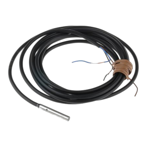
The pin assignment is as follows.Wire only required pins.
Pin No.
1
Signal name
RESET
Wire color
(ZFX-VP)
Signal
direction
Function
Brown Input Restarts the ZFX.
2
TRIG Red Input Measurement trigger signal input
3
DI0 Orange Input Command parameter
4
DI1 Yellow Input
5
DI2 Green Input
6
DI3 Blue Input
7
DI4 Purple Input
8
DI5 Gray Input Command input
9
DI6 White Input
10
DI7 Black Input
11
InputDI8 Brown Input Parallel command confirmation signal
12
DSA Red Input Data send request signal input
13
OR Orange Output Level output / pulse output
14
ERROR Yellow Output ON when an error occurs
15
RUN Green Output ON while in the RUN mode
16
ENABLE Blue Output ON when measurement trigger signal
can be input
17
GATE Purple Output
18
DO15 Gray Output
ON for the preset output time
19
COMIN White
Data output
20
COMOUT Black
Common for input signals, STGOUT0
and STGOUT1
Common for OR, ERROR, RUN,
ENABLE, GATE, DO15 signals
-
-
Hold down the two latch locks on both sides of the connector of the parallel I/O cable
(ZFX-VP) to unlock the connector, and connect it to the Controller’ s parallel I/O
connector 1. To lock the connector again,release the latch locks.
2
3
4
1
20
20 11
11
10
10
1
1
Pin No.
2011
101
Pin No.
Parallel I/O cable
ZFX-VP (2 m/5 m)
Specification of a parallel I/O cable
Item
Manufacturer name
Model number
Electric wire size (thickness)
Total cable width
Cable length
Connector
Hirose electric Co. Ltd.
FX2B-20SA-1.27R
-
-
-
Flat cable
Hitachi Cable, Ltd.
UL20012-ST10×28AWG
0.89 mm
12.70 mm
2 m / 5 m
Pin No. Signal name Function
10
11
12
13
14
15
16
17
18
19
Common for STGOUT0, STGOUT1, and
DO0 to DO6 signals
(Leave open)
20 Common for DO7 to DO14 signals
DO7
DO8
DO9
DO10
DO11
DO12
DO13
DO14
COMOUT
(OPEN)
COMOUT
Wire color
(ZFX-VP)
Black
Brown
Red
Orange
Yellow
Green
Blue
Purple
Gray
White
Black
Signal
direction
Output
Output
Output
Output
Output
Output
Output
Output
-
-
-
*1: Use the STGOUT0 or STGOUT1 signal when you want to connect a strobe device
to the ZFX.
Pin No.
1
2
3
4
5
Signal name
STGOUT0
STGOUT1
Function
Strobe trigger 0 output
Strobe trigger 1 output
Data output
6
7
8
9
DO0
DO1
DO2
DO3
DO4
DO5
DO6
Wire color
(ZFX-VP)
Brown
Red
Orange
Yellow
Green
Blue
Purple
Gray
White
Signal
direction
Output
Output
Output
Output
Output
Output
Output
Output
Output
COMIN
Respective
terminal
COMIN
Respective
terminal
TRIG signal
Mode
Input voltage
ON current *1
ON voltage *1
OFF current *2
OFF voltage *2
NPN
12 to 24 VDC±10%
5mA min.
ON delay
OFF delay
Internal circuit
diagram
8.8 V min.
0.5 mA max.
0.8 V max.
0.1 ms max.
0.1 ms max.
PNP
12 to 24 VDC±10%
5mA min.
8.8 V min.
0.5 mA max.
0.8 V max.
0.1 ms max.
0.1 ms max.
*1:The ON current/voltage is the value of the current/voltage that changes the status
from OFF to ON. The value of the ON voltage is the potential difference between
COM IN and each input terminal.
*2:The OFF current/voltage is the value of the current/voltage that changes the status
from ON to OFF. The value of the OFF voltage is the potential difference between
COM IN and each input terminal.
*3:The ON/OFF delay time for TRIG signal is different from the circuit diagram for
RESET, DI0 to DI8, and DSA signals.
OR, ERROR, RUN, ENABLE, GATE, DO0 to DO15 signals
Mode
Output voltage
Load current
ON residual voltage
OFF leakage current
NPN
12 to 24 VDC±10%
45mA max.
Internal circuit
diagram
2 V max.
0.2 mA max.
PNP
12 to 24 VDC±10%
45mA max.
2 V max.
0.2 mA max.
Respective
terminal
Load
COMOUT Respective
terminal
COMOUT
Load
COMOUT
Load
Respective
terminal
COMIN
STGOUT 0 to 1 signals
Mode
Output voltage
Load current
ON residual voltage
OFF leakage current
NPN
12 to 24 VDC±10%
45mA max.
Internal circuit
diagram
2 V max.
0.2 mA max.
PNP
12 to 24 VDC±10%
45mA max.
2 V max.
0.2 mA max.
4.5 82
72
(130)
52
6.58
38.42
(75)
760.23
(Unit: mm)
2.Specifications
Item
Number of connected cameras
Connectable camera
Processing resolution
Display
ZFX-C20
2 1
ZFX-SR_/SC_/S/SC
When ZFX-SR_SC_ is connected:464(H)×464(V)
When ZFX-S/SC is connected:608(H)×464(V)
ZFX-C10HZFX-C25 ZFX-C15H
LCD monitor
Indicator
Parallel
interface
Circuit type
3.5” TFT color LCD (320×240 pixels)
“Measuring” indicator (color: green): RUN
Trigger indicator (color: blue): ENABLE
Judgment indicator (color: orange): OUTPUT
Error indicator (color: red): ERROR
12 points (RESET, DSA, DI0 to 8, TRIG)
23 points (OR, ERROR,
RUN, ENABLE, GATE,
STGOUT0 to 1,
DO0 to 15)
22 points (OR, ERROR,
RUN, ENABLE, GATE,
STGOUT0,
DO0 to 15)
NPN
1 port, FULL SPEED, MINI-B connector
External
I/F
Support
Menu language
Operation I/F
Main
functions
Ratings
Input
Output
PNP NPN PNP
Serial
interface
USB2.0
RS-232C
RS-422
1 port, max. 115200 bps (cannot be used
simultaneously with RS-422 interface)
1 port, max. 115200 bps (cannot be used
simultaneously with RS-232C interface)
Network
communi-
cations
Ethernet 1 port, 100BASE-TX/10BASE-T (to be expanded
in the future)
Monitor output
Memory card I/F
Analog RGB output, 1 ch
(resolution VGA: 640 ×480)
SD card slot 1 ch
Touch panel, key operation, console connection
Number of registered
banks
32 banks
Number of setup items 128 items/1 bank
Measure-
ment items
Shape inspection
Size inspection
Edge inspection
Brightness/color
inspection
Application-based
inspection
Pattern search, sensitive search, flexible search, graphic search
Area, labeling
Position, width, count
Brightness, HUE
Defects, Grouping
Position correction
1 model search, 2 model search, position, area, labeling
Image memory function Max. 100 images
Japanese/English (can be switched)
Power supply
voltage
21.6 to 26.4 VDC (including ripple)
Current consu-
mption
1.5 A max. 1.2 A max.
Insulation
resistance
Across all lead wires and controller case: 20MΩ
(by 250 V megger)
Operation environ-
ment robustness
Dielectric
strength
Across all lead wires and controller case, 1000
VAC, 50/60 Hz, 1 min
Ambient temp-
erature range
Operating: 0 to +50℃, Storage: -15 to +60℃
(with no icing or condensation)
Ambient atmo-
sphere
Ambient humi-
dity range
Operating and storage: 35% to 85% (with no co-
ndensation)
No corrosive gases allowed
Degree of
protection
IP20 (IEC60529)
Material
Weight
Accessories
Vibration
resistance
(durability)
Vibration frequency:
10 to 150 Hz Single-amplitude:0.35 mm
Acceleration: 50m/s
2
10 times for 8 minutes
Shock resistance
(destructive)
150 m/s
2
3times each in 6 directions
(up/down, left/right, forward/backward)
Case: Polycarbonate (PC), Plate face: PMMA
Approx. 650 g
Touch pen (ZFX-TP), Exhaust unit (ZFX-EU),
Terminal block adapter (ZFX-XTB), Ferrite core
(2 p’ ces), Power connector, Instruction Sheet
(this paper)
Ratings
(90)
122
32
145
(130) 15
PRECAUTIONS FOR CORRECT USE
・
When using a commercially available switching regulator, make sure that the
FG terminal is grounded.
Do not use thinner, benzene, acetone or kerosene to clean the Camera and
Controller. If large dust particles adhere to the Camera, use a blower brush
(used to clean camera lenses) to blow them off. Do not use breath from your
mouth to blow the dust off. To remove dust particles from the Camera, wipe
gently with a soft cloth(for cleaning lenses)moistened with a small amount of
alcohol. Do not use excessive force to wipe off dust particles. Scratches to the
Camera might cause error.
3. Maintenance and Inspection
Attach ferrite cores (supplied) to both ends of
the camera’ s cable and the Controller’ s
power cable, respectively.
1. Hook the Controller’ s upper hook onto the DIN track.
2. Push the Controller down onto the DIN track until its
lower hook is snapped into place.
・Attach the End Plate (sold separately) to both sides of the
Controller on the DIN track.
・Attach the Exhaust Unit (supplied) to the Controller when
installing other devices adjacently on the same DIN track as the
Controller.
1. Pull the Controller’ s lower hook downwards.
2. Lift up the Controller from its bottom to remove
it from the DIN track.
Observe the following precautions to prevent failure to operate, malfunctions, or
undesirable effects on product performance.
Do not install this product in locations subjected to the following conditions:
・Ambient temperature outside the rating
・Rapid temperature fluctuations (causing condensation)
・Relative humidity outside the range of 35 to 85%
・Direct vibration or shock
・
Reflection of intense light (such as other laser beams or electric arc-welding
machines)
・Direct sunlight or near heaters
・Strong magnetic or electric field
1. Installation Site
2. Power Supply and Wiring
・
If surge currents are present in the power lines, connect surge absorbers that suit the
operating environment.
・
Before turning ON the power after the product is connected, make sure that the
power supply voltage is correct, there are no incorrect connections (e.g. load
short-circuit) and the load current is appropriate. Incorrect wiring may result in
breakdown of the product.
・
Before connecting/disconnecting cables, make sure that the product is turned OFF.
The product may breakdown if it is connected/disconnected while the power is ON.
・
For cables, use only the exclusive products specified in this manual.
・
Use only combinations of the Camera and Controller specified in this manual.
・
Do not turn the power OFF in the following instances. Doing so will damage data
that is in the process of being saved.
-While data is being saved on the Controller
-While data is being saved on the SD card
・
The
LCD monitor has been made using precision technology, and sometimes a few
pixels are missing in the panel. This is due to the structure of the LCD monitor, and
is not a malfunction.
・
Do not remove the base from the Camera.
・
Use the screws of accessory when fixing the terminal block. The product miqht
break when using the screws other than accessory.
© OMRON Corporation 2007 All Rights Reserved.
ModelZFX-C20/C25
/C10H/C15H
Smart Sensor
For Model ZFX-S□□□Controller
・Presence of corrosive or flammable gases
・Presence of dust, salt, or iron particles
・Water, oil, or chemical fumes or spray,or mist atmospheres
Also, do not install this product in locations subjected to the following conditions
to ensure its protective performance as described in the specifications:
To improve heat radiation, install the Controller only in the orientation show below.
Do not install the Controller in the following orientations.
・Install the Controller so that the distance between the Controller and other devices is
at least the dimensions shown in the figure below to improve the ventilation.
・Keep the ambient temperature less than 50℃.If the ambient temperature is higher
than 50℃,install a fan forced cooling system or an air conditioner to keep
the temperature lower than 50℃.
・Avoid mounting on a panel, in which high-voltage emitting devices are installed to
prevent ZFX-C operation from being affected by noise.
・Allow at least 10 m between the Controller and power lines to keep noise at a low
level in the operating environment.
Name
(1)Monitor
connector
Function
This connector is for connecting to the LCD monitor (option) via a
monitor cable.
(2)Camera
connector
This connector is for connecting to a camera.Only connector 1
for camera 0 is provided on the ZFX-C10H/C15H.
Name
(1)Ethernet port
Function
This port is for connecting to a personal computer via a 100Base-
TX/10Base-T cable.
(2)RS-232C/422
connector
This connector is for connecting to a PLC via an RS-232C or an
RS-422 cable.
(3)Console
connector
This port is for connecting to the Console.
(4)Power
connector
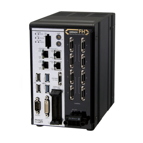
This connector is for connecting to the DC power supply.
(5)Parallel port This port is for connecting to devices such as a PLC using the
parallel cable.
Use a power supply that meets the following specifications.
Item
Power supply Voltage
Specification
Approx. 24 VDC (21.6 to 26.4 VDC)
Output current 1.5 A min.
Recommended power supply S8VS-06024 (24 VDC, 2.5 A)
Recommended electric wire size 0.14 to 1.5 mm2 (max. 1 m)
Ferrite coreFerrite core
+-
Ferrite core
When attaching ferrite cores to the
Controller's power cable, pass the
cable once through each ferrite core.
DC power
supply
1
2
DIN track (sold separately)
PFP-100N (1 m)
PFP-50N (0.5 m)
PFP-100N2 (1 m)
PULLOPEN
1 2 3 4
O
M
RON
ZFX-C10
OUTPUT RUN ERROR ENABLE
MENU RUN
SD
CARD
ADJ
USB
AUTO ESC
SET
End Plate (sold separately)
PFP-M
Exhaust Unit
1
2
Attach the Exhaust Unit (supplied) to the Controller when installing other devices next
to the Controller on the same DIN track. The Exhaust Unit also serves as the Touch Pen
Holder
Exhaust Unit
Touch Pen Holder 1. Attach the Exhaust Unit to the four
mounting holes on the Controller.
Right
Wrong Wrong
ETHERNET
PARALLEL1
CONSOLE
RS-232C
PARALLEL0
(1)
(4) (5)
(2) (3)
PULLOPEN
1 2 3 4
O
M
RON
ZFX-C10
OUTPUT RUN ERROR ENABLE
MENU RUN
SD
CARD
ADJ
USB
AUTO ESC
SET
(1)
(4)
(2)
(3)
(9)
(5)
(6)
(7)
(8)
Front Operation
panel cover
Top Bottom
●Top
●Bottom
Use a DC power supply with countermeasures against high voltages (safe extra
low-voltage circuits on the secondary side). If the system must meet UL standards, use
a UL class Ⅱpower supply.
Before communicating with a host device, make sure that the product has started up.
Also, clear the receive buffers on the device in use or perform other measures since
undetermined signals might be output from the host interface when this product is
started up.
24 VDC
-
+
Loosen the two screws on the top of the
Power connector (male) using a flat-blade
screwdriver.
Insert the DC power terminal (wire) into the
Power connector (male) and tighten the two
screws on the top of the Power connector to
fasten the power terminal with the
screwdriver.
Tightening torque:0.22 to 0.25 N・m.
Plug the Power connector (male) into the
Controller’ s Power connector (female).
Tighten the two screws on the left and right
of the Power connector (male) with the
screwdriver to fasten it.
Tightening torque:0.22 to 0.25 N・m.
1
3
4
2
Important
CAMERA1
RGB
CAMERA2
(1) (2)
Wire the Terminal Block Adapter (supplied) and plug it into the Controller’ s parallel I/O
connector 0
Signal cable
Cable width : 0.14 mm2to 1.0 mm2
Cable length : 30 m
Tightening torque for the respective wire : 0.22 to 0.25 N・m
Tightening torque for the Terminal Block Adapter : 0.3 N・m
Terminal block adapter mounting screws:M2.6×7 screws
(accessories, 4p'ces)
Instead of the Terminal Block Adapter, the parallel I/O cable (ZFX-VP) can be connected
to it as well. The wiring of the parallel I/O cable is the same as that of the parallel I/O
connector 1.
Note
ETHERNET
RS-232C
CONSOLE
PARALLEL1
1
11
10
20
Pin No.
Thisproductcontainsalithiumbatteryforwhichthefollowingnoticeapplies:
PerchlorateMaterial-specialhandlingmayapply.
Seewww.dtsc.ca.gov/hazardouswaste/perchlorate
Dimensions
The following signal words are used in this manual.
U.S. California Notice
The following alert symbols are used in this manual.
Indicates a potentially hazardous situation which, if not avoided, will result in minor
or moderate injury, or may result in serious injury or death. Additionally there may
be significant property damage.
Indicates the possibility of explosion under specific conditions.
The following alert statements apply to the products in this manual. Each alert statement also appears at
the locations needed in this manual to attract your attention.
PRECAUTIONS ON SAFETY
4. About the cap of the camera connector
Please put up the cap to the camera connector not used when you use only
one camera of the cap of the camera connector.
5. Installation Precautions
97.5
7.5
3.Input Specifications
RESET, DI0 to DI8, and DSA signals
COMIN
Respective
terminal
COMIN
Respective
terminal
Mode
Input voltage
ON current *1
ON voltage *1
OFF current *2
OFF voltage *2
NPN
12 to 24 VDC±10%
5mA min.
ON delay
OFF delay
Internal circuit
diagram
8.8 V min.
0.5 mA max.
1.1 V max.
5 ms max.
0.7 ms max.
PNP
12 to 24 VDC±10%
5mA min.
8.8 V min.
0.5 mA max.
1.1 V max.
5 ms max.
0.7 ms max.
6. Attaching ferrite core
7. Installing and Removing
10.Communication with a Host Device
7.1 Installing on the DIN Track
7.2 Removing Procedure
8. Attaching the Exhaust Unit to the Controller
9. Power supply specification
9.1 Recommended power supply
5.1 Heat radiation
5.2 Ventilation
9.2 Connecting Procedure
Specification
1. Part Names and Functions
Name
(1)Indicator
(2)LCD monitor/
touch panel
(3)Function keys
(4)Touch pen
(5)USB port
(6)SD card slot
(7)Mode switch
(8)Control keys
(9)Strap holder for
touch pen
Function
The LCD monitor displays setup menus and images captured
from the cameras. Various settings can be made on the touch
panel by tapping menu buttons in the LCD monitor using the
touch pen.
Specific functions are allocated to the Function keys.
The touch pen is used to operate the touch panel. This pen can be
attached to the Controller by tying its strap to the strap holder for
the touch pen.
This port is for connecting to a personal computer via a USB cable.
This slot is for inserting the SD Card.
This switch selects the operation mode.
MENU
ADJ
RUN
Select this mode when setting measurement conditions.
Select this mode when adjusting setting parameters as necessary
referencing the image and values displayed on the LCD monitor
during continuous test measurement (measurement without
measurement data output to external devices).
Select this mode when performing measurement.
These keys are used to perform operations without the use of the
touch pen.
This holder is for attaching the touch pen.
Note:The judgment result is output to the OR signal via the parallel interface.
●Front
“Measuring” indicator
Error indicator ERROR
RUN Lights in green when in the RUN mode.
Lights in red when an error occurs.
Judgment indicator OUTPUT
Lights in orange when the judgment result
is OK or NG according to the setting.(Note)
Trigger indicator ENABLE Lights in blue when the ZFX-C is ready
for the measurement trigger input.
When installing Controller only:
When installing the Controller With the Exhaust Unit
attached:
Min.50 mm
Min.15 mm
Min.50 mm Min.
15 mm
Data output
5.Parallel I/O Connector 0 (Standard Parallel Port)
6.Parallel I/O Connector 1 (Extended Parallel Port)
4.Output Specifications
Thank you for selecting OMRON product. This sheet primarily
describes precautions required in installing and operating the product.
Before operating the product, read the sheet thoroughly to acquire
sufficient knowledge of the product. For your convenience, keep the
sheet at your disposal.
Refer to the user’ s manual for details.
INSTRUCTION SHEET
・Do not attempt to dismantle, repair, or modify the product.
・Dispose of this product as industrial waste.
・Never use this product for safety devices used in nuclear power facilities or those
used for the protection of human life.
・When using this product, make sure that safety measures such as fail-safe devices
are implemented.
(3) Others
This product is compliant with the standards below:
EN Standards(European Standards), EN61326-1
Electromagnetic environment : Industrial electromagnetic environment
(EN/IEC 61326-1 Table 2)
Also, the following condition is applied to the immunity test of this product.
: If the level of disturbance of the video is that with
characters on the monitor are readable, the test is pass.
(4) Regulations and Standards
The pin assignment is as follows. Wire only required pins.
Please observe the following precautions for safe use of the products.
PRECAUTIONS FOR SAFE USE
・Do not use the product in environments where it can be exposed to
inflammable/ explosive gas.
・Install the product in such a way that its ventilation holes are not blocked.
・To secure the safety of operation and maintenance, do not install the
product close to high-voltage devices and power devices.
(1) Installation Environment
・The supply voltage must be within the rated range (DC24V±10%).
・Reverse connection of the power supply is not allowed.
・Open-collector outputs should not be short-circuited.
・Use the power supply within the rated load.
・High-voltage lines and power lines must be wired separately from this product.
Wiring them together or placing them in the same duct may cause induction,
resulting in malfunction or damage.
・For cables, do not use excluding the special cable. It might cause the
malfunction or damage.
(2) Power Supply and Wiring
A lithium battery is built into the Controller and may occasionally combust, explode, or
burn if not treated properly.
Dispose of the Controller as industrial waste, and never disassemble, apply pressure
that would deform, heat to 100 ℃or higher, or incinerate the Controller.
COMIN
Load
Respective
terminal
COMOUT
・Do not use excluding the combinations of the Camera and Controller specified in
this manual. It might cause the malfunction or damage.
・Tighten the camera connector by a regulated torque, 0.15N・m.
NOTICE:
This product meets CISPR11 class A. The intended use of this product
is in an industrial environment only.
Do not connect it with STGOUT1 for ZFX-C10H/C15H.
Note:Only connector 1 for camera 0 is provided on the ZFX-C10H/C15H.
Manufacturer:
Omron Corporation,
Shiokoji Horikawa, Shimogyo-ku,
Kyoto 600-8530 JAPA N
TRACEABILITY INFORMATION:
Importer in EU :
Omron Europe B.V.
Wegalaan 67-69
2132 JD Hoofddorp,
The Netherlands
●NoticeforKoreaRadioLaw
A급 기기(업무용 방송통신기자재)
이 기기는 업무용(A급) 전자파적합기기로서 판매자
또는 사용자는 이 점을 주의하시기 바라며,가정외의
지역에서 사용하는 것을 목적으로 합니다.
Suitability for Use
s
Omron Companies shall not be responsible for conformity with any standards,
codes or regulations which apply to the combination of the Product in the
Buyer’s application or use of the Product. At Buyer’s request, Omron will
provide applicable third party certification documents identifying ratings and
limitations of use which apply to the Product. This information by itself is not
sufficient for a complete determination of the suitability of the Product in
combination with the end product, machine, system, or other application or
use. Buyer shall be solely responsible for determining appropriateness of the
particular Product with respect to Buyer’s application, product or system.
Buyer shall take application responsibility in all cases.
NEVER USE THE PRODUCT FOR AN APPLICATION INVOLVING
SERIOUS RISK TO LIFE OR PROPERTY WITHOUT ENSURING THAT THE
SYSTEM AS A WHOLE HAS BEEN DESIGNED TO ADDRESS THE RISKS,
AND THAT THE OMRON PRODUCT(S) IS PROPERLY RATED AND
INSTALLED FOR THE INTENDED USE WITHIN THE OVERALL
EQUIPMENT OR SYSTEM.
See also Product catalog for Warranty and Limitation of Liability.
Oct, 2014
D
OMRON Corporation Industrial Automation Company
Contact: www.ia.omron.com
Tokyo, JAPAN
OMRON ELECTRONICS LLC
2895 Greenspoint Parkway, Suite 200
Hoffman Estates, IL 60169 U.S.A.
Tel: (1) 847-843-7900/Fax: (1) 847-843-7787
OMRON ASIA PACIFIC PTE. LTD.
No. 438A Alexandra Road # 05-05/08 (Lobby 2),
Alexandra Technopark,
Singapore 119967
Tel: (65) 6835-3011/Fax: (65) 6835-2711
OMRON (CHINA) CO., LTD.
Room 2211, Bank of China Tower,
200 Yin Cheng Zhong Road,
PuDong New Area, Shanghai, 200120, China
Tel: (86) 21-5037-2222/Fax: (86) 21-5037-2200
OMRON EUROPE B.V.
Sensor Business Unit
Carl-Benz-Str. 4, D-71154 Nufringen, Germany
Tel: (49) 7032-811-0/Fax: (49) 7032-811-199
Regional Headquarters
