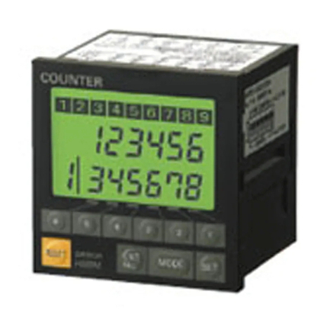
Omron H7CN User manual

1
Solid-state Counter H7CN
All Required Counter Functions
Incorporated in a Compact DIN-sized
(48 x 48) Housing
In addition to Up and Down models, a reversible
(Up-Down) counter is also available
Maximum counting speed of 5,000 cps, never
before attained by a small-size preset counter
Power supply freely selectable within a range of
100 to 240 VAC. Also, power supply for the
DC-operated
models is
selectable within a range of
12 to 48 V
Models with memory backup function against
power failure available RC
Ordering Information
Classification Preset Counter Totalizing
Counter
Input
signal sys
-
tem (Count & reset
inputs)
Contact, Solid-state
Contact/Solid-state
Mounting method
Flush mounting, surface mounting
Display
7-segment LEDs (8 mm high), Up indicator
7-segment LEDs
(8 mm high)
Number of digits
4 digits (0 to 9,999)
Backup power for
memory protection
No Y
es (100 to 240 V
AC
only)
Backup time for
power interruption:
Approx. 5 years at
20°
C (approx.
10 min without bat
-
tery)
No Yes
Backup time for
power interruption:
Approx. 5 years at
20°
C (approx.
10 min without bat
-
tery)
Control output
Contact (SPST
-NO)
Contact (SPDT)
Contact (SPST
-NO)
Solid-state (open-
collector) ---
Operating mode
Up
counting Down
counting Up
counting Down
counting Reversible
counting, com
-
mand input
Reversible
counting, indi
-
vidual input
Up
counting Down
counting
Up counting
Max.
counting
d
30 cps
H7CN-XLN H7CN-YLN H7CN-
XLNM H7CN-
YLNM H7CN-ALN H7CN-BLN --- --- H7CN-TXL
counting
speed
5 kcps
(see
note)
H7CN-XHN H7CN-YHN H7CN-
XHNM H7CN-
YHNM H7CN-AHN H7CN-BHN H7CN-
XHNS H7CN-
YHNS H7CN-TXH
Note: Only
the solid-state input signal is available when the maximum counting speed is 5,000 cps
Accessories (Order Separately)
Protective
Cover
Hard Y92A-48B
o ec e Co e
Soft Y92A-48D
Flush Mounting Adapter
Y92F-30
Backup Battery
Y92S-20
Sockets
Applicable
Counter T
rack Mounted
Socket
Back Connecting
Socket
H7CN-jj P2CF-08 P3G-08
H7CN-jjM P2CF-11 P3GA-11

H7CN H7CN
2
Specifications
Ratings
Supply
voltage
24, 100 to 240 V
AC 50/60 Hz
12 to 48 VDC (contains 20% ripple max.) (see note 1)
Operating voltage range
85% to 1
10% of rated voltage
Power consumption
(see note 2)
Approx. 12 V
A/2.5 W (at 240 V
AC, 50Hz)
Approx. 2.5 W (at 48 VDC)
Count and reset input
Impedance by short-circuiting contacts: 1 k
Ω
max.
Residual voltage: 2 V max.
Impedance by opening contacts: 100 k
Ω
min.
Max. counting speeds of
count input
30 cps (contact and solid-state inputs)
Minimum pulse width: 16.7 ms (ON/OFF ratio: 1:1)
5.000 cps (solid-state inputs)
Minimum pulse width: 0.1 ms (ON/OFF ratio: 1:1)
Reset system
Power-OFF reset
Reset time: 0.5 s
Reset time following power application 0.05 s
External reset & manual reset
Reset time: 0.02 s
Reset time following signal application: 0.05 s
Control output
Contact (SPDT) output:
3 A, 250 V
AC, cosϕ
= 1 (resistive load)
Solid-state (open collector) output:
30 VDC MAX. 100 mA max.
Note: 1.
The memory backup function is not available for this DC supply voltage range.
2.
On power application, an inrush current of approximately 10 times the normal current flows through the Counter
.
Characteristics
Item Preset Counter Totalizing Counter
Insulation resistance
100 M
Ω
min. (at 500 VDC) (between
current-carrying terminal and exposed
non-current-carrying metal parts, and between
non-continuous contacts)
100 M
Ω
min. (at 500 VDC) (between
current-carrying terminal and exposed
non-current-carrying metal parts)
Dielectric strength
2,000 V
AC, 50/60 Hz for 1 min (between
current-carrying terminal and exposed non-current
carrying metal parts and between non-continuous
contacts)
2,000 V
AC, 50/60 Hz for 1 min (between
current-carrying terminal and exposed non-current
carrying metal parts)
Impulse withstand voltage
6 kV (between power terminals)
6 kV (between current-carrying terminal and exposed non-current-carrying metal parts)
Noise immunity
±
2 kV (between power terminals),
±
500 V (between input terminals),
square-wave noise by noise simulator
Static immunity
Malfunction: 8 kV
V
ibration resistance
Destruction:
10 to 55 Hz, 0.75-mm single amplitude
Malfunction:
10 to 55 Hz, 0.5-mm single amplitude
Shock resistance
Destruction:
300 m/s
2
(approx. 30G)
Malfunction:
100 m/s
2
(approx. 10G)
Ambient temperature
Operating: –10
°
C to 55
°
C (with no icing)
Storage: –25
°
C to 65
°
C (with no icing)
Ambient humidity
35% to 85%
Life expectancy
Mechanical:
10 million operations min.
Electrical:
100,000 operations min.
(3 A at 250 V
AC, resistive load)
---
Approved standards
UL508, CSA C22.2 No.14
Weight
Approx. 150 g

H7CN H7CN
3
Engineering Data
Electrical Life Expectancy
(Resistive load) (Inductive load)
Load current (A) Load current (A)
Operation
Timing Charts
Preset Counter
Up
T
ype Down Type
Reset
Preset
Digital
display
Control
output
0
Count-up
Reset
Preset
Digital
display
Control
output
0
Count-up
Up/Down A, B Types
Reset
Preset
Digital
display
Control
output
0
Count-up

H7CN H7CN
4
Totalizing Counter
Up
T
ype
Reset
*Full scale
Digital display
* Full scale: 9999
0
Input Mode
Up/Down Selectable Type
Note: (A)
must be more than the minimum signal width. If (A) is set shorter than the minimum signal width, the error of count
±
1 may occur
.
Up
mode
Down mode
Count input 1: Count input; Count input 2: Inhibit (gate) input
Count
input
1
Count
input 2
Inhibited
Count value
Note: Input
to the CP2 while the CP1 is set to “L.”
Count input 1: Count input; Count input 2: Inhibit (gate) input
Count
input
1
Count
input 2
Inhibited
Count value
Note: Input
to the CP1 while the CP2 is set to “H.”
Count input 1: Inhibit (gate) input; Count input 2: Count input
Count
input
1
Count
input 2
Inhibited
Count value
Note: Input
to the CP2 while the CP1 is set to “L.”
Count input 1: Inhibit (gate) input; Count input 2: Count input
Count
input
1
Count
input 2
Inhibited
Count value
Note: Input
to the CP1 while the CP2 is set to “H.”
Up/Down Type
Note: (A)
must be more than the minimum signal width. If (A) is set shorter than the minimum signal width, the error of count
±
1 may occur
.
Up/Down
A command input
Count
input
1
Count
input 2
Count value
Up/Down
B individual input
Count
input
1
Count
input 2
Count value
H:
Short-circuit ON-time impedance; 1 k
Ω
max. Residual voltage; 0.5 V max.
L: Open circuit OFF-time impedance; 100 k
Ω
min.

H7CN H7CN
5
Dimensions
Accessories
Adapter for Flush Mounting
Y90F-30
Panel Y92F-30 Flush
Mounting Adapter
P3G-08
Back
Connecting
Socket
Panel Cutout
The standard panel cutout is as shown below. (Panel cutout con-
forms
to DIN43700.)
Panel cutout for side-by-side mounting of two or more Units
When
mounting n Counters in a line, dimension A can be calculated
from
following formula.
A = (48n-2.5)
+1
0
Connecting Sockets
H7CN
Front
Mounting
H7CN
P2CF-08
103.7
H7CN
+
Adapter
Y92F-30
P3G-08
Flush
Mounting
95.1
H7CN-jjNM
Front Mounting
P2CF-11
H7CN
114.6116.9 H7CN
+
Adapter
Y92F-30
P3GA-11
Flush
Mounting

H7CN H7CN
6
Protective Cover
The
Protective Cover shields the front panel, particularly the count
value
setting section from dust, dirt and water
,
and prevent malfunc
-
tioning
of the Counter due to static electricity
.
Y92A-48B (Hard cover)
(see note 1) Y92A-48D (Soft cover)
(see note 2)
Note: 1. The
Hard Protective Cover prevents the set count value
from being altered due to accidental contact with the
push-type
thumbwheel switch.
2. The
Soft Protective Cover allows the set value to be set
by
depressing the thumbwheel switches through it.
It
may be, however
, dif
ficult to make setting changes of
the Counter with the Y92A-48B Protective Cover at-
tached, which must be taken into consideration before
using
the Y92A-48B Protective Cover
.
Backup Battery for Memory Protection
Y92S-20
Red lead wire
(0.18 x 12 cond
u
L = 120 mm
4.5 dia. hole
Installation
Terminal Arrangement
Presetting
Model
(with No Backup Function)
Presetting Model
(with Backup Function)
T
otalizing Model
(with No Backup Function)
Common
of
CP1 and CP2
reset inputs
Reset input
CP1 input
CP2 input
Output circuit
Power
input
Note: 1. Terminal
2 is a negative terminal
and
terminal 7 is a positive termi
-
nal
if DC power is supplied.
2. Common terminal 1 is internally
connected to terminal 2 if the
Counter
is a model that operates
with DC.
Note: 1. If
Y92S-201 is
not used, make
sure that the voltage of the
battery
is 3 V
.
2. All
data will be held for approx
-
imately 10 minutes if no bat-
tery
is used.
Note: 1. Terminal
2 is a negative terminal
and
terminal 7 is a positive termi
-
nal
if DC power is supplied.
2. Common terminal 1 is internally
connected to terminal 2 if the
Counter
is a model that operates
with DC.
Common
of
CP1 and CP2
reset inputs
Reset input
CP1 input
CP2 input
Y92S-20 or
equivalent
battery
Common of
CP1 and CP2
reset inputs
Reset input
CP1 input
CP2 input
Power
input
Power
input
Connections
Power Supply Connection
For
Models with No Backup Function
For Models with
Backup Function
AC Power Supply DC Power Supply
100 to 240 VAC 12 to 48 VDC 100 to 240 VAC
Note: 1. Make
sure that the fluctuation of the supply voltage is within the permissible range.
2.
Pay attention to the polarity of the DC power supply and do not make a wiring mistake.

!
H7CN H7CN
7
Input Connection
The
CP1 and CP2 reset inputs of the H7CN will be active when input to the H7CN is short-circuited.
Solid-state Input (NPN)
Contact Input
Sensor
CP1 (N)
CP2 (N)
(Reset)
Input common
*H: Solid-state ON
*Refer
to the following
for the signal levels of
the
solid-state input.
Note: 1.
H level with solid-state ON.
Residual voltage: 0.5 V max.
ON impedance: 1 k
Ω
max.
2.
L level with solid-state OFF
.
OFF impedance: 100 k
Ω
min.
*Make sure that the contact can switch
0.5 mA
at 5 V with ease.
*Sensors
with
voltage output can be con
-
nected to the H7CN as shown in the
above
circuit diagram. When solid-state
is OFF, make sure that the voltage be-
tween the input common and CP1 or
CP2
terminals are 4
V min. for AC mod
-
els
and 6 V min. for DC models.
Sensor
CP1 (N)
CP2 (N)
(Reset)
Input common
*H: Solid-state ON
CP1 (N)
CP2 (N)
(Reset)
Input common
*H: Contact ON
(30 V max.)
Output (Load) Connection
Contact Output
Solid-state Output
Load
*Diode to absorb counter-electromotive force
250 VAC max.
Load
30 VDC max.
Delay
T
ime
The
delay time, which is the
period between the moment a pulse in
-
put
signal that coincides
with the preset value is ON and the moment
the
corresponding control output
signal is ON, varies with the count
-
ing
speed and type of output as shown in the following table.
Control output
Max. counting speed Delay time
Contact output
30 Hz (cps)
12 to 13.5 ms
Co ac ou u
5 kHz (cps)
5.5 to 8 ms
Solid-state output
5 kHz (cps)
0.65 to 0.7 ms
Precautions
Caution
The
Y92S-20, which is used for the H7CN-
jj
NM, is a battery for
power failure backup. Do not short
the positive and negative poles
of
the battery
, recharge or disassemble it, deform it with pressure, or
throw
it into a fire, otherwise it may explode, burn, or leak liquid.
Correct Use
Battery
for Power Failure Backup
Be sure to connect a battery to the Counter if it is a model with a
backup function. A variety of 3-V batteries can be used. The data
backup time of the Counter varies with the electric capacity of the
battery.
Before
using the Counter for the first time, turn ON
the Counter and
reset
it. Since output may be sent out when the power is turned ON,
be
sure to keep the output terminals open when turning ON the pow
-
er.
If
a power failure to the
Counter occurs for longer than 10 minutes
with
the
battery disconnected, the Counter will have output errors or
display
errors when power is supplied to the Counter again, in
which
case
reset the Counter before use. (The Counter can be used with
or
without the battery if it is reset.)
The
life of the battery depends on the frequency of power failures.
It
is, however, recommended that the battery be replaced regularly
(i.e., every four to five years).
Y92S-20
or
equivalent battery

H7CN H7CN
8
Connection
To terminal 1 To terminal 4
To terminal 4
To terminal 1
To terminal 1
Power
Supply
, Input, and Output
The
Counter requires 50 ms to be in stable operation after power is
supplied.
Do not input any signal before the Counter is in stable
op
-
eration.
Power
supply
Do not input signals during this period, when
the Counter is not in stable operation.
Refer
to
the following for the condition of the Counter after an instan
-
taneous
power failure if the Counter has no backup function.
Instantaneous
power failure
0.5 s min. The display and output are reset.
Power
supply
Condition after instantaneous
power failure
0.01 s max. The previous condition is on hold.
0.01 to 0.5 s
Either the previous condition is on hold
or the display and output are reset.
Note: If
the previous condition must be on hold, use the H7CN-M,
which
has a backup function.
Display and Output
•The
display of the Counter will be turned OFF when the external
reset
or manual
reset signal is input. The Counter will display the
reset
value when it has been reset.
•The Counter reads input signals anytime and it is possible to
change the set value of the Counter while power is being
supplied.
Be aware that the Counter will have an output signal if
the
set value coincides with the count value while changing
the
set
value.
To prevent the set value from being changed by mistake while
operating the Counter, use the Y92A-48B Protective Cover,
which
is sold separately
.
•Set each value to 0 and reset or turn the H7CN OFF and ON.
Then the control output will be obtained instantly and can be
used
to test the system, unless the model is one other than the
H7CN-M
with a backup function.
•When
changing the set value while power is being supplied, do
not leave a set value set midway between numbers, otherwise
the
Counter will have a set value error
.
ALL DIMENSIONS SHOWN ARE IN MILLIMETERS.
To
convert millimeters into inches, multiply by 0.03937. T
o convert grams into ounces, multiply by 0.03527.
Cat. No. M004-E1-7B
OMRON Corporation
Industrial
Automation Company
Measuring and Supervisory Controls Division
28th Fl., Crystal T
ower Bldg.,
1-2-27, Shiromi, Chuo-ku,
Osaka 540-6028 Japan
Phone: (81)6-6949-6035 Fax: (81)6-6949-6069
In the interest of product improvement, specifications are subject to change without notice.
Printed
in Japan
0399-0.5C (1
198)
Table of contents
Other Omron Cash Counter manuals

Omron
Omron CS1W-CT041 User manual

Omron
Omron GO SMART HJ-203 User manual

Omron
Omron Walking style One 2.0 User manual

Omron
Omron H7BR Series User manual

Omron
Omron H7GP - User manual

Omron
Omron H7BR Series User manual

Omron
Omron H7ET Series User manual

Omron
Omron H7CX - User manual

Omron
Omron H7CR-A Series User manual

Omron
Omron H7E-P Series User manual

Omron
Omron H7CZ-L8 User manual

Omron
Omron H7CL Series User manual

Omron
Omron H8CA-S Series User manual

Omron
Omron C200H-CT021 User manual

Omron
Omron SYSMAC C200H-CT001-V1 User manual

Omron
Omron SYSMAC CS Series User manual

Omron
Omron H7CX-R11D1 User manual

Omron
Omron CS1 - User manual

Omron
Omron H7CZ Series User manual

Omron
Omron H7CX Series User manual