manuals.online logo
Brands
  1. Home
  2. •
  3. Brands
  4. •
  5. Omron
  6. •
  7. Computer Hardware
  8. •
  9. Omron CP1L-E User manual

Omron CP1L-E User manual

!!PNSPO!
!
Lean Automation Kit
Quick Start Guide – CP1L-E & NB HMI
Introduction:
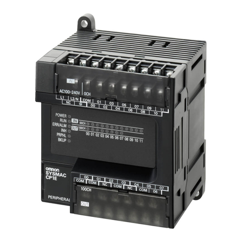
This document describes the procedure to setup your Lean Automation Kit. Your kit
comprises of a CP1L-E Ethernet-equipped PLC, NB-series colour touchscreen HMI
(Ethernet), Westermo SDI-550 5-port Ethernet switch, and S8VS-06024 24VDC power
supply. Optionally, you may have selected a CP1W analogue I/O expansion module and a
JX or MX2 inverter and/or SmartStep2 servomotor system.
You will also have been supplied with all necessary cables and communication modules
for the inverter and/or servo options, a CD containing samples software (for both PLC and
HMI) and a library of technical manuals.
If you have any questions regarding the assembly or operation of your kit, please call:
Technical Support Team: 0870 752 0871
or visit www.myOMRON.com
Scope of Kits:
Each kit contains an NB-series colour touchscreen HMI which is connected to the CP1L-E
PLC via the Westermo 5-port Ethernet switch, using the supplied CAT6 patch cable.
CX-Programmer V8.2 upwards (part of the CX-One V3 or V4 Automation Suite) is required
to program this PLC, which you may have purchased optionally with your kit.
NB-Designer (supplied on the resource CD) is used to program the HMI.
The sample PLC and HMI software applications provided on the resource CD illustrate
how pre-written Function Blocks (FB) simplify the communication process between the
PLC and inverter(s), allowing full control and parameterisation whilst eliminating the need
for traditional digital I/O links between the devices.
For the SmartStep2 servomotor system option, high-speed pulse I/O control is used for
speed and position reference, supported by dedicated PLC instructions. Again, pre-written
PLC and HMI applications are provided on the resource CD to demonstrate these
functions.
revision 2.0 (December 2012)
OMRON ELECTRONICS LTD ●Technical Support: 0870 752 0871 or visit www.myOMRON.com
2
OMRON ELECTRONICS LTD ●Technical Support: 0870 752 0871 or visit www.myOMRON.com
3
Preparation:
Installing the Analogue I/O Option Module:
1. Remove the blanking cover from the leftmost Option Board position of the CP1L-E
PLC (Slot 1) and insert the CP1W-ADB21/DAB21V/MAB221 module.
2. If you have ordered the JX or MX2 inverter option, please insert the CP1W-CIF11
RS422/485 option module into the rightmost Option Board position (Slot 2). The
supplied software application for the JX/MX2 inverter is written assuming that that
this module will be located in Slot 2*
* Note that CP1L-E20 models only have one expansion slot on the front of the CPU; this is designated as ‘Slot 2’
Wiring the PLC, HMI and power supply:
The S8VS-06024 power supply included with your kit is capable of supplying 2.5A at
24VDC, which is intended to supply the required power to the CP1L-E PLC, the NB-series
HMI, the Westermo 5-port Ethernet switch and all I/O signals to the inverter and
servomotor systems. If you are connecting additional devices to the outputs of the PLC
that require 24VDC, please be aware of the maximum current capability of this power
supply.
1. Using 0.5mm2– 2.0mm2cable, connect a 230VAC mains supply to the S8VS-
06024 in accordance with datasheet T01E-EN-02 (see Resource CD > TECHNICAL
DOCUMENTATION > S8VS PSU )
2. Using 0.5mm2(20AWG) wire, connect the ‘+V’ output terminal of the S8VS-06024
power supply to the ‘+’ input terminal of the PLC and the ‘24V’ terminal of the NB-
series HMI
3. Using 0.5mm2(20AWG) wire, connect a ‘jumper’ between the ‘+’ terminal of the
PLC and the ‘COM’ terminal, as show in diagram 1 overleaf.
4. Using 0.5mm2(20AWG) wire, connect the ‘-V’ output terminal of the S8VS-06024
power supply to the ‘-’ input terminal of the PLC and the ‘0V’ terminal of the NB-
series HMI
5. Using 0.5mm2(20AWG) wire, connect ‘jumpers’ between the first four ‘COM’
terminals of the PLC output terminal block and a longer wire to the ‘-V’ output
terminal of the S8VS-06024 for NPN configuration (CP1L-M30DT-D model) or to
the ‘+V’ terminal for PNP configuration (CP1L-M30DT1-D model). This step is only
necessary if you have selected the SmartStep2 servomotor option.
6. Connect the NQ-CN222 cable between the NQ HMI and the PLC, connecting the
end marked “PT” to the HMI.
Note: If you selected the SmartStep2 servomotor option, you will have been supplied with
a transistor output PLC, either CP1L-M30DT-D (NPN outputs) or CP1L-M30DT1-D (PNP
outputs). Pleas ensure that you follow the correct wiring procedure depending on your
model; page 18 for PNP or page 20 for NPN. Although the inputs (to the PLC) may be
wired for NPN or PNP, the shown configuration provides NPN inputs, which are necessary
for compatibility with the SmartStep2 output signals.
If you have not chosen the SmartStep2 option, you can wire the inputs for PNP
configuration, by connecting the ‘COM’ terminal to the adjacent ‘-‘ (0V) terminal.
OMRON ELECTRONICS LTD ●Technical Support: 0870 752 0871 or visit www.myOMRON.com
4
L N E
230VAC
MAINS
SUPPLY
0V 24V
24V 0V
24V 0V
0V for NPN
24V for PNP
NQ-CN222
NQ3-TQ (HMI – Rear)
CP1L-M30 (PLC)
S8VS-06024
(
Power Su
pp
l
y)
OMRON ELECTRONICS LTD ●Technical Support: 0870 752 0871 or visit www.myOMRON.com
5
Wiring the JX inverter option:
The JX-series inverters feature built-in RFI filters, so no additional external filters are
required.
Before wiring the JX inverter, please refer to the “Precautions for Safe Use” section (pages
5-9) of the User’s Manual,ref: I558-E2-02 (see Resource CD > TECHNICAL DOCUMENTATION > JX
INVERTER)
It is not necessary to connect a motor to the JX inverter whilst testing ‘on the bench’.
However, if a motor is connected, please refer to the wiring instructions in section 2-2.
L N E
230VAC
MAINS
SUPPLY
U
V
W
OMRON ELECTRONICS LTD ●Technical Support: 0870 752 0871 or visit www.myOMRON.com
6
Serial communication connection between the JX inverter and PLC:
The JX inverter will be controlled entirely by MODBUS commands over the RS485 serial
communication link (to the CP1L PLC), so no ‘hard’ I/O wiring is required. Your Lean
Automation Kit will have been supplied with a communication cable which fits between the
RJ45 (‘Ethernet-style’) socket on the front of the JX and the screw terminals of the CP1W-
CIF11 RS422/485 communications option module, fitted in the right-hand slot of the CP1L
PLC.
1. Insert the RJ45 connector end into the front of the JX inverter (located behind the
rubber flap)
2. Connect the GREEN wire into the first terminal of the CP1W-CIF11 communications
option module, marked ‘RDA-‘
3. Connect the WHITE/BLUE wire into the second terminal of the CP1W-CIF11
communications option module, marked ‘RDB+ ‘
4. Remove the CP1W-CIF11 module from the PLC; set the DIP switches (at the rear
of the unit) according to the diagram below:
Setting the JX communications parameters for MODBUS:
OMRON ELECTRONICS LTD ●Technical Support: 0870 752 0871 or visit www.myOMRON.com
7
By default, the JX is set to accept its speed reference from the front-mounted “volume”
potentiometer and run command signal from the built-in keypad.
In order for the JX to be controlled entirely over MODBUS, the parameters and settings
detailed below must be changed.
The sample software application included on the resource CD uses MODBUS settings of
9,600bps (baud rate), 8 data bits, 1 stop bit and no parity, and also assumes that the JX
has a node number (network address) of 1. Therefore, a couple of other parameters also
need to be changed from their defaults.
Please refer to section 3-4 “Operating Procedure” of User’s Manual I558-E2-02 if you are
unfamiliar with the operation of the front panel keypad. (see Resource CD > TECHNICAL
DOCUMENTATION > JX INVERTER)
1. Change parameter A001 to a value of “03” to enable the setting of the frequency
reference via MODBUS
2. Change parameter A002 to a value of “03” to enable the setting of RUN command
selection via MODBUS
3. Change parameter C070 to a value of “03” – this defines that the RJ45 port will be
used for MODBUS communication rather than for the connection of an external
operator keypad panel
4. Change parameter C071 to a value of “05” – this changes the communication baud
rate to 9600 (used in the sample program) from the default of 4800 baud
5. Turn off the power to the JX inverter (setting procedure continued over page…)
OMRON ELECTRONICS LTD ●Technical Support: 0870 752 0871 or visit www.myOMRON.com
8
6. Loosen the screw in the bottom left corner of the inverter and remove the front
cover
7. Turn DIP switch ‘S7’ to the upper ‘485’ position, as indicated in the diagram below
(leave switch ‘S8’ in its default OFF position)
8. Replace the front cover and reapply power to the inverter
OMRON ELECTRONICS LTD ●Technical Support: 0870 752 0871 or visit www.myOMRON.com
9
Wiring the MX2 inverter option:
Your MX2 inverters will have been supplied with an appropriate RFI footprint filter, AX-
FIM101-RE.
Before wiring the MX2 inverter, please refer to the “Precautions for Safe Use” section of
the User’s Manual, ref: I570-E2-01 (see Resource CD > TECHNICAL DOCUMENTATION > MX2
INVERTER)
It is not necessary to connect a motor to the MX2 inverter whilst testing ‘on the bench’.
However, if a motor is connected, please refer to the wiring instructions in section 2-3-12
and earthing/EMC recommendations in section D-1-2
to motor
(if used)
from filter
captive cables
230VAC
MAINS
SUPPLY
OMRON ELECTRONICS LTD ●Technical Support: 0870 752 0871 or visit www.myOMRON.com
10
1. Attach the MX2 inverter to the filter using the M4 screws (4 off) supplied with the
filter.
2. Attach a suitable 230VAC mains supply to the terminal block of the filter, ensuring
that the earth is securely connected to the stud to the left of the terminal block,
using a crimp-on eyelet. For MX2-AB002-E (0.25kW) and MX2-AB004-E (0.4kW)
models, AWG16/1.3mm2cable should be used. For the MX2-AB007-E (0.75kW)
model, AWG12/3.3mm2cable should be used. (See section 2-3-6 of User’s Manual
I570-E2-01 for further details and fuse protection recommendations.)
3. The filter includes captive AC supply cables which should be connected accordingly
to the L1 (Live) and N (Neutral) screw terminals of the MX2 inverter, as shown in
the diagram on the previous page. The Earth wire is terminated into an eyelet
which should be attached to the leftmost M4 chassis ground screw. (See section 2-
3-11 of User’s Manual I570-E2-01 for further details.)
4. If used, connect the motor to the MX2 inverter in accordance with the wiring
instructions in section 2-3-12.
5. Perform the pre-check and power-up tests as detailed in section 2-4.
Serial communication connection between the MX2 inverter and PLC:
The MX2 inverter will be controlled entirely by MODBUS commands over the RS485 serial
communication link (to the CP1L PLC), so no ‘hard’ I/O wiring is required.
Your Lean Automation Kit will have been supplied with a 2m twisted-pair cable which fits
between the ‘SN’ and ‘SP’ terminals of the MX2 and the screw terminals of the CP1W-
CIF11 RS422/485 communications option module, fitted in the right-hand slot of the CP1L
PLC.
OMRON ELECTRONICS LTD ●Technical Support: 0870 752 0871 or visit www.myOMRON.com
11
Up to 31 inverters may be connected to a MODBUS ‘master’ (in this case, the CP1L PLC),
using unshielded, twisted-pair cable is used to ‘daisy chain’ them together. Suitable cable
is Belden 9502 or equivalent.
1. Using the supplied cable, connect the black wire to the first screw terminal of the
CP1W-CIF11 module (marked RDA-) and the red wire to the second screw terminal
(marked RDB+).
2. At the MX2 end, connect the black wire to the terminal marked SN and the red wire
to SP, as shown in the diagram above.
3. Turn the “DIP switch for termination resistor” (marked ‘MD SW1’ - see diagram on
previous page for location) to the right, to its ON position.
4. Remove the CP1W-CIF11 module from the PLC; set the DIP switches (at the rear
of the unit) according to the diagram below:
OMRON ELECTRONICS LTD ●Technical Support: 0870 752 0871 or visit www.myOMRON.com
12
Setting the MX2 communications parameters for MODBUS:
By default, the MX2 is set to accept speed reference and run command signals from the
built-in front panel keypad and external digital input signals.
In order for the MX2 to be controlled entirely over MODBUS, the following parameters
(A0001 and A0002 in bold, below) must be changed. Please be sure to reboot the power
to the inverter after changing these parameters in order for the new settings to take effect.
The sample software application included on the resource CD uses MODBUS settings of
9,600bps (baud rate), 8 data bits, 1 stop bit and no parity, and also assumes that the MX2
has a node number (network address) of 1. Therefore, no other parameters need to be
changed from the defaults, as they already match these settings.
Please refer to section 2-5 of User’s Manual I570-E2-01 if you are unfamiliar with the
operation of the front panel keypad.
OMRON ELECTRONICS LTD ●Technical Support: 0870 752 0871 or visit www.myOMRON.com
13
Using the built-in safety features of the MX2 inverter
The MX2 inverter enables safety compliance to PLd (“Performance Level d”), ISO13849-2
cat4, SIL3, when used with a suitable safety relay unit such as the Omron G9SA-301.
Ensure that power is removed from the MX2 and remove the front cover. Just above the
screw terminal block are three single DIP switches in a horizontal row…
Turning the middle switch to the ON position sets digital inputs 3 and 4 to be used as
normally-closed safety inputs. This action automatically forces drive parameters C003=77
and C004=78 to define the use of these safety inputs.
Turning the right-most DIP switch to the ON position defines that output terminal 11 is to
be used as an external safety monitor (EDM) output.
The wiring diagram on the following page assumes that a single 2 x NC (normally closed)
contact emergency stop switch is to be used with a single MX2 inverter.
The Omron G9SA-301 safety relay unit is shown wired for manual reset (i.e., the MX2 will
not be reset until the button is pressed), but it can, of course, be wired to automatically
reset once the E-stop button is released. Please refer to G9SA manual ref J121-E2-03A
for alternative wiring details.
The MX2’s “P24” (24VDC) terminal provides power to the safety relay’s I/O circuit (G9SA
terminals 13 and 23).
Please ensure that the metal jumper across the “L” and “PLC” terminals of the MX2
remains in place (this is its factory default position). This is the MX2’s internal power
supply 0VDC connection for I/O connections.
OMRON ELECTRONICS LTD ●Technical Support: 0870 752 0871 or visit www.myOMRON.com
14
As stated on the previous page, MX2 inputs 3 and 4 become dedicated safety inputs once
the [middle] DIP switch SF SW1 is turned ON.
Similarly, with the [right-most] DIP switch EDM SW1 turned to the ON position, output 11
becomes a dedicated EDM (External Device Monitor) output for use with the external
safety monitoring relay.
Operation;
With the E-stop button in its “released” position and the reset switch “open”, the MX2 will
run as normal.
As soon as the E-stop button is pressed, the MX2’s power outputs (to the motor) are
instantly ‘cut’. Please bear in mind that depending on the application, this may cause the
motor to coast to a stop. In some cases, it may be preferable to perform a controlled stop
of the motor (using the inverter’s DC injection braking) before removing the power.
The MX2 will display an “E37.□” error code to indicate that a safe stop has occurred.
Once the E-stop is released and the RESET button has been pressed, the MX2 will revert
to normal operation.
Please be aware that it could instantly start again if the command inputs and frequency
reference remain set.
OMRON ELECTRONICS LTD ●Technical Support: 0870 752 0871 or visit www.myOMRON.com
15
Wiring the SmartStep2 servo option:
The 100W, 200W and 400W SmartStep2 servomotor system will have been supplied with
the R7A-FIB104-RE footprint RFI filter. The R7D-BP0 servomotor amplifier should be
attached to this filter using the supplied M4 screws.
1. Connect a 230VAC supply to the filter, as shown in the diagram above, ensuring
that an earth connection is made to the M4 stud behind the terminal block.
2. Connect the output power connector from the filter into ‘CNA’ of the servo amplifier.
Attach the flying earth cable eyelet to one of the two earthing screws to the left side
of this connector.
L N E
230VAC
MAINS
SUPPLY
filter side
view
OMRON ELECTRONICS LTD ●Technical Support: 0870 752 0871 or visit www.myOMRON.com
16
3. Attach the motor encoder cable (R88A-CRGB001-5CR-E) between terminal ‘CN2’
of the servo amplifier and the short flying cable at the rear of the servomotor.
4. Attach the motor power cable (R88A-CAB001-5SR-E) between terminal ‘CNB’ of
the servo amplifier and the short flying cable nearer the shaft end of the servomotor.
5. Attach the control I/O cable (R7A-CPB001S) into terminal ‘CN1’ of the servo
amplifier and secure the retaining screws.
OMRON ELECTRONICS LTD ●Technical Support: 0870 752 0871 or visit www.myOMRON.com
17
Connecting the control I/O signals between the SmartStep2 and PLC;
The PLC provides output signals to the SmartStep2 for RUN, RESET, ECRST (deviation
counter reset), CW (clockwise pulses) and CCW (counter-clockwise pulses).
The SmartStep2 provides the following signals back to the PLC; /ALM (alarm condition,
normally closed), INP (positioning completed) and Z (encoder Z phase). For 100W, 200W
and 400W SmartStep2 servo amplifiers, these output signals are NPN only. To
accommodate this, the PLC inputs are wired accordingly as NPN (sinking), i.e., for the
inputs, the commons are connected to +24VDC
The output signals from the PLC to the SmartStep2 are wired as PNP or NPN, depending
on the CP1L model selected (CP1L-M□□DT-D has NPN outputs, CP1L-M□□DT1-D has
PNP outputs). Wiring diagrams for both configurations are shown on the next pages, so
be sure to follow the correct one for your chosen CP1L.
The CW (clockwise) and CCW (counter-clockwise) signals into the SmartStep2 amplifier
must be 5V TTL level compatible; as we are working with a 24VDC supply, these levels
must be ‘dropped’ using 2KΩresistors, to prevent damage to the input circuitry. A resistor
module is included with the kit for this purpose. Alternatively, you may prefer to solder
(and heatshrink protect) your own 2KΩresistors in series with the CW and CCW
connections.
Please refer to the diagram overleaf for full wiring details…
1. Cut-back about 25cm of the outer sheathing and braiding from the R7A-CPB001S
control I/O cable.
2. Separate the YELLOW (1 RED BAND) and YELLOW (1 BLACK BAND) wires, twist
these together and connect them (via a screw-terminal block or solder) to the +24V
terminal of the S8VS power supply.
3. Separate the GREY (3 BLACK BANDS), WHITE (3 BLACK BANDS), ORANGE (1
RED BAND), GREY (2 RED BANDS) and GREY (2 BLACK BANDS) wires, twist
these together and connect them (via a screw-terminal block or solder) to the 0V
terminal of the S8VS power supply.
4. Connect the ORANGE (3 RED BANDS) wire to input 0.06 – this is the ‘Z’ output
from the servomotor encoder, used to datum the system.
5. Connect the PINK (1 RED BAND) wire to input 1.04 – this is the ‘ALARM’ signal
(normally closed) which indicates that the system is in error.
6. Connect the PINK (1 BLACK BAND) wire to input 1.05 – this is the ‘IN POSITION’
signal which indicates that the drive has completed its move successfully.
7. Cut the GREY (3 RED BANDS) wire and connect to one side of the resistor module.
Connect the off-cut of this cable to the other side of the resistor module, then to
output 100.00 – this is the ‘CLOCKWISE PULSES’ command signal.
8. Cut the WHITE (3 RED BANDS) wire and connect to one side of the resistor
module. Connect the off-cut of this cable to the other side of the resistor module,
then to output 100.01 – this is the ‘COUNTER CLOCKWISE PULSES’ command
signal.
PNP VERSION FOR CP1L-M30DT1-D
OMRON ELECTRONICS LTD ●Technical Support: 0870 752 0871 or visit www.myOMRON.com
18
9. Connect the GREY (1 BLACK BAND) wire to output 100.04 – this is the ‘ERROR
COUNTER RESET’ signal which resets the drive’s internal following error counter in
the event of a fault caused by this.
10.Connect the ORANGE (1 BLACK BAND) wire to output 100.06 – this is the ‘RUN’
command signal to the drive.
11.Connect the GREY (1 RED BAND) wire to output 100.07 – this is the ‘RESET’
signal to the drive, to be used after an error.
OMRON ELECTRONICS LTD ●Technical Support: 0870 752 0871 or visit www.myOMRON.com
19
SmartStep2 servo amplifier to PLC wiring;
PNP CONFIGURATION FOR CP1L-M30DT1-D MODEL
OMRON ELECTRONICS LTD ●Technical Support: 0870 752 0871 or visit www.myOMRON.com
20
Please refer to the diagram overleaf for full wiring details…
1. Cut-back about 25cm of the outer sheathing and braiding from the R7A-CPB001S
control I/O cable.
2. Separate the ORANGE (1 RED BAND), WHITE (3 RED BANDS) and GREY (3
RED BANDS) wires, twist these together and connect them (via a screw-terminal
block or solder) to the +24V terminal of the S8VS power supply.
3. Separate the YELLOW (1 RED BAND), YELLOW (1 BLACK BAND), GREY (2 RED
BANDS) and GREY (2 BLACK BANDS) wires, twist these together and connect
them (via a screw-terminal block or solder) to the 0V terminal of the S8VS power
supply.
4. Connect the ORANGE (3 RED BANDS) wire to input 0.06 – this is the ‘Z’ output
from the servomotor encoder, used to datum the system.
5. Connect the PINK (1 RED BAND) wire to input 1.04 – this is the ‘ALARM’ signal
(normally closed) which indicates that the system is in error.
6. Connect the PINK (1 BLACK BAND) wire to input 1.05 – this is the ‘IN POSITION’
signal which indicates that the drive has completed its move successfully.
7. Cut the GREY (3 BLACK BANDS) wire and connect to one side of the resistor
module. Connect the off-cut of this cable to the other side of the resistor module,
then to output 100.00 – this is the ‘CLOCKWISE PULSES’ command signal.
8. Cut the WHITE (3 BLACK BANDS) wire and connect to one side of the resistor
module. Connect the off-cut of this cable to the other side of the resistor module,
then to output 100.01 – this is the ‘COUNTER CLOCKWISE PULSES’ command
signal.
9. Connect the GREY (1 BLACK BAND) wire to output 100.04 – this is the ‘ERROR
COUNTER RESET’ signal which resets the drive’s internal following error counter in
the event of a fault caused by this.
10.Connect the ORANGE (1 BLACK BAND) wire to output 100.06 – this is the ‘RUN’
command signal to the drive.
11.Connect the GREY (1 RED BAND) wire to output 100.07 – this is the ‘RESET’
signal to the drive, to be used after an error.
NPN VERSION FOR CP1L-M30DT-D

This manual suits for next models

1

Other Omron Computer Hardware manuals

Omron CP1L CPU UNIT - 03-2009 User manual

Omron

Omron CP1L CPU UNIT - 03-2009 User manual

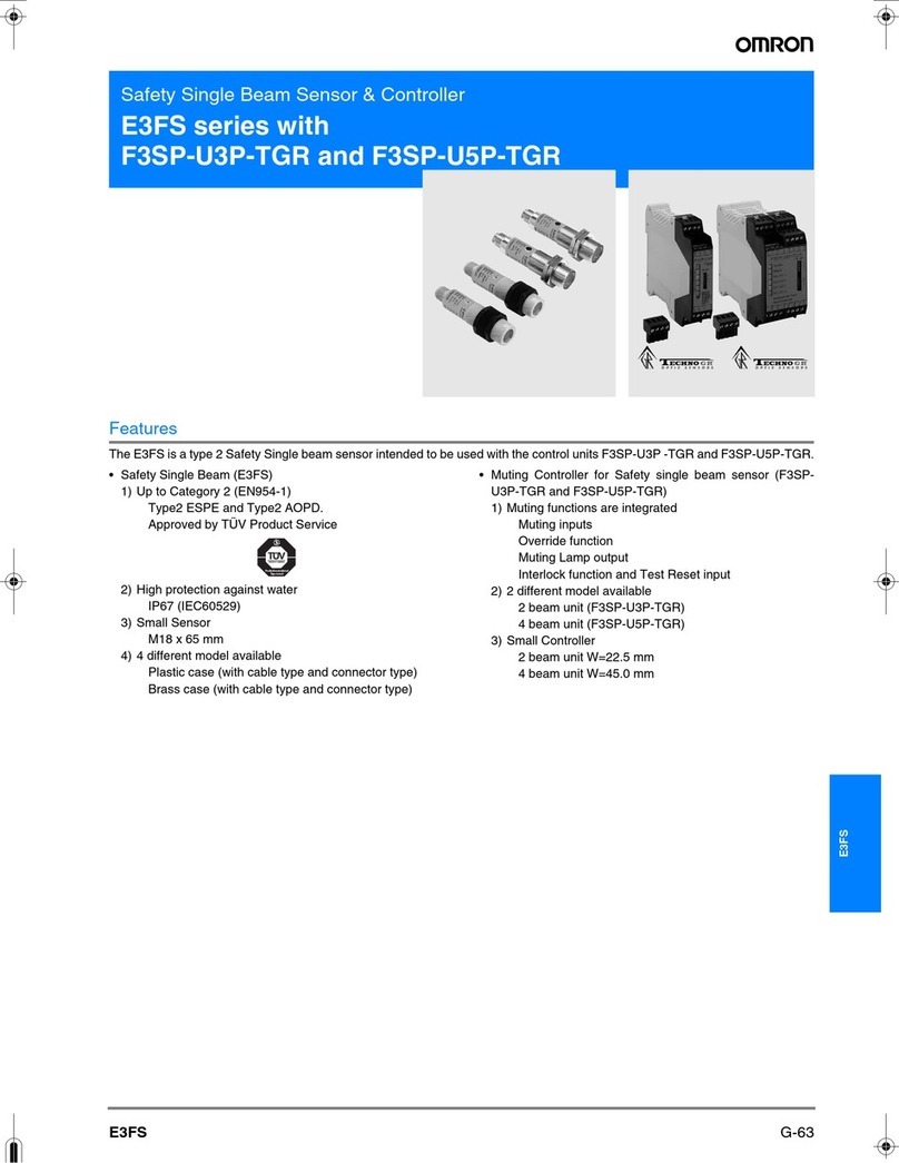
Omron F3SP-U3P-TGR User manual

Omron

Omron F3SP-U3P-TGR User manual

Omron G3PB User manual

Omron

Omron G3PB User manual

Omron G3PB User manual

Omron

Omron G3PB User manual

Omron H8PS User manual

Omron

Omron H8PS User manual

Omron SYSMAC CJ2H-CPU6@-EIP Instruction Manual

Omron

Omron SYSMAC CJ2H-CPU6@-EIP Instruction Manual

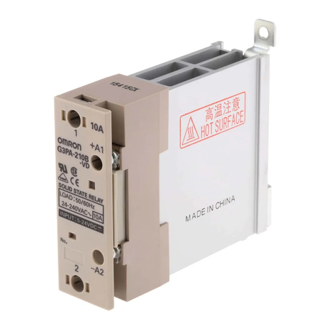
Omron G3PA User manual

Omron

Omron G3PA User manual

Omron G2RS User manual

Omron

Omron G2RS User manual

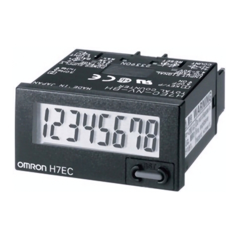
Omron H7E User manual

Omron

Omron H7E User manual

Omron New H7E Series User manual

Omron

Omron New H7E Series User manual

Omron CP1H CPU UNITS - PROGRAMMING  05-2007 User manual

Omron

Omron CP1H CPU UNITS - PROGRAMMING 05-2007 User manual

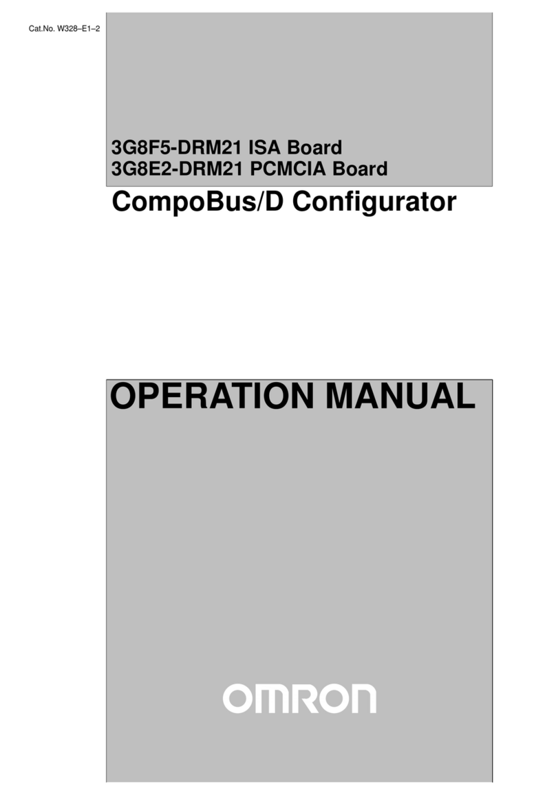
Omron 3G8F5-DRM21 User manual

Omron

Omron 3G8F5-DRM21 User manual

Omron E5ZN-DRT Configuration guide

Omron

Omron E5ZN-DRT Configuration guide

Omron R88A-MCW151-DRT-E User manual

Omron

Omron R88A-MCW151-DRT-E User manual

Omron ACCURAX G5 - User manual

Omron

Omron ACCURAX G5 - User manual

Omron FJ-AP1 User manual

Omron

Omron FJ-AP1 User manual

Omron CVM1 Series User manual

Omron

Omron CVM1 Series User manual

Omron C1SD-PD

Omron

Omron C1SD-PD

Omron SYSMAC CP Series User manual

Omron

Omron SYSMAC CP Series User manual

Omron CQM1H - 08-2005 User manual

Omron

Omron CQM1H - 08-2005 User manual

Omron PYF S User manual

Omron

Omron PYF S User manual

Omron CS1W-CRM21 User manual

Omron

Omron CS1W-CRM21 User manual

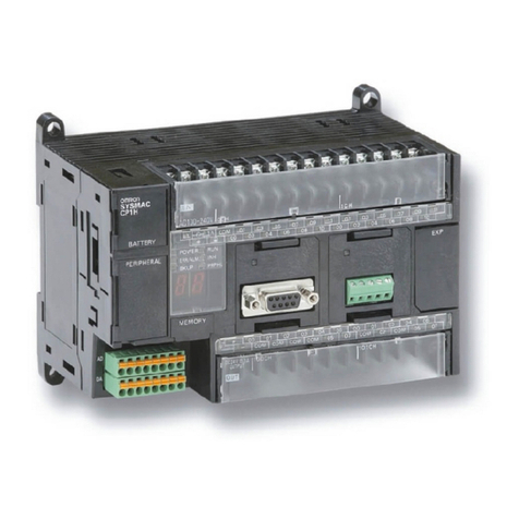
Omron CP1L User manual

Omron

Omron CP1L User manual

Omron CP1L - 12-2007 User manual

Omron

Omron CP1L - 12-2007 User manual

Popular Computer Hardware manuals by other brands

MikroTik RouterBOARD 751U-2HnD user manual

MikroTik

MikroTik RouterBOARD 751U-2HnD user manual

Lab.gruppen LUCIA quick start guide

Lab.gruppen

Lab.gruppen LUCIA quick start guide

AVIRE Digital Audio Unit installation guide

AVIRE

AVIRE Digital Audio Unit installation guide

MSI MS-98C7 manual

MSI

MSI MS-98C7 manual

RF Tech World Key quick guide

RF Tech

RF Tech World Key quick guide

Delta Electronics Suppression Inductors LFZ24H Specification sheet

Delta Electronics

Delta Electronics Suppression Inductors LFZ24H Specification sheet

4ms Company SCMBO Builder's guide

4ms Company

4ms Company SCMBO Builder's guide

Renesas SH7751 Group user manual

Renesas

Renesas SH7751 Group user manual

Kodak X-Omat 1000 Service manual

Kodak

Kodak X-Omat 1000 Service manual

Aerocool Hexform user manual

Aerocool

Aerocool Hexform user manual

One Stop Systems OSS-PCIe-HIB2-EC-x1 user manual

One Stop Systems

One Stop Systems OSS-PCIe-HIB2-EC-x1 user manual

ekwb EK-Pro user guide

ekwb

ekwb EK-Pro user guide

Konica Minolta SRX-101A Service manual

Konica Minolta

Konica Minolta SRX-101A Service manual

ARTERY AT32F435 Series Reference manual

ARTERY

ARTERY AT32F435 Series Reference manual

AMX VTX-2 Schematic diagram

AMX

AMX VTX-2 Schematic diagram

HP F768WM user guide

HP

HP F768WM user guide

NXP Semiconductors KTTWR17510EVBUG user guide

NXP Semiconductors

NXP Semiconductors KTTWR17510EVBUG user guide

Lenovo ThinkAgile MX user guide

Lenovo

Lenovo ThinkAgile MX user guide

manuals.online logo
manuals.online logoBrands
  • About & Mission
  • Contact us
  • Privacy Policy
  • Terms and Conditions

Copyright 2025 Manuals.Online. All Rights Reserved.