ix
About this Manual:
This
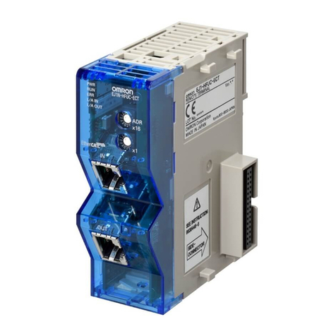
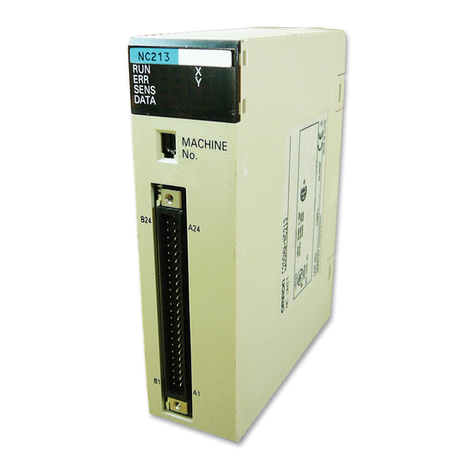
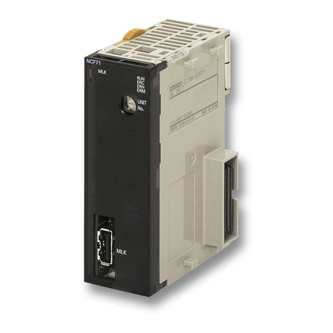
manual describes the installation, setup, and operation of the 3G8F5-CLK1
1-E/CLK21-E Controller
Link
Support Boards and includes the sections described below
. Controller Link Support Boards are used
to
connect IBM PC/A
T or compatible computers to a Controller Link Network. The following three manuals
are directly related to application of the Controller Link Network.
Name Contents Cat. No.
(suffixes omitted)
SYSMAC 3G8F5-CLK11-E,
3G8F5-CLK21-E
Controller Link Support Boards
Operation Manual (this manual)
Installation, setup, and operating procedures for
Controller Link Support Boards. Controller Link
Support Boards are used to connect IBM PC/ATs or
compatibles to a Controller Link Network.
W307
SYSMAC C200HW-ZW3AT2-E,
3G8F5-CLK11-E/CLK21-E,
Controller Link Support Software
Operation Manual
Installation and operating procedures for the
Controller Link Support Software. The Controller
Link Support Software enables manually set data
links and other procedures for a Controller Link
Network.
W308
SYSMAC CS1W-CLK11/21,
C200HW-CLK21, CVM1-CLK21
Controller Link Units
Operation Manual
Installation, setup, and operating procedures for the
Controller Link Units. Controller Link Units are used
to connect C200HX/HG/HE and CV-series PCs to a
Controller Link Network.
W309
Depending
on the system, you may also need the SYSMAC or CV Support Software or a Programming
Console.
Refer to the body of this manual for details. Please read this manual and related manuals care
-
fully
and be sure you understand the information provided before attempting to install and operate a
Con
-
troller Link Support Board.
Section
1
outlines the
features of the Controller Link Support Board, including the applications of the Con
-
troller Link Support Board and the
dif
ferences
between the Controller Link Support Board and the Control
-
ler Link Unit.
Section
2
describes the methods for setting switches on
the Controller Link Support Board, installing the
Support Board in a computer, and wiring the Controller Link Network.
Section
3
describes
the procedure for installing the software necessary for using a Controller Link Sup
-
port Board.
Section
4
describes how to create
applications (user programs) that control the Controller Link Support
Board.
Section
5
gives details on the C-language library commands and
driver calls used by the Controller Link
Support Board.
Section 6
describes how to use data links in a Controller Link Network.
Section 7
explains how to use the message service provided by a Controller Link Support Board.
Section 8
describes the method used to connect multiple networks through CV-series PCs and
CS1-series
PCs.
Section
9
provides details on Controller Link Network communications. Refer to this section for network
communications that require accurate communications timing.
Section 10
provides information on troubleshooting errors that occur during Controller Link Support
Board operation, as well as daily inspection, cleaning, and other maintenance procedures.
Appendix
provides a list of standard OMRON products related to Controller Link Networks.
WARNING Failure to read and understand the information provided in this manual may result in
personal injury or death, damage to the product, or product failure. Please read each
section
in its entirety and be sure you understand the information provided
in the section
and related sections before attempting any of the procedures or operations given.
!
