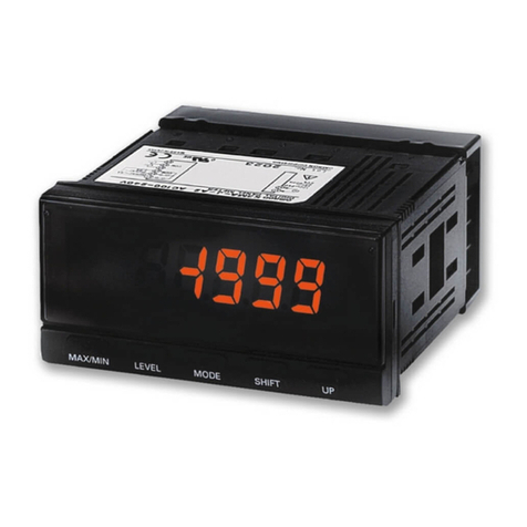
Omron H7CC-A Series User manual

1
Digital Counter/Tachometer
H7CC
New and improved design for easier use,
programming, maintenance and user feedback
The improved user interface is intuitive and
offers better overall visibility. Replacement
time notification function notifies the user of
potential preventive maintenance
Basic Features
• The white-color display offers better visual clarity and visibility, and the color universal
design is used.
• Up/Down Keys are provided for all six digits, which reduces the number of button
operations during setup and other processes.
• An easy operation is realized by the operation guide on which each key lights up.
• The progress can be easily understood at one glance from the status indicators
of the present value and the measurement value.
• The body depth of all models with screw terminals has been reduced to 59 mm.
Safety and Reliability
• The replacement time is notified in advance by predicting the service life.
• The power supply circuit and input circuits are isolated in all models, and therefore, there is no need of any wiring restrictions.
Other Features
• Follows the ratings, characteristics, and functionality of the H7CX-N.
• Equipped with the Output Allocation and Output ON/OFF Inversion Function.
• Equipped with a Memory Backup and H7AN Compatibility Function to facilitate problem-free conversion from H7CN/H7AN.
Features
Basic Features
Better visual feedback and operation
The white-color display offers better visual clarity and visibility, and
the color universal design is used. The keys of all six digits can be
operated up/down for easier use. The LED indicator of the operable
keys lights up to support setup.
Status Notification by Status Indicator
The status can be indicated by the ratio of the present value or measurement
value to the set value, which makes it easy to understand the status.
Shortened Body
The body depth of all models with screw terminals has been reduced
to 59 mm, which contributes to thinner control panels!
Safety and Reliability
Notification of Replacement Time
The service life prerequisites of the counter include the relay output
count and the deterioration of the electrolytic capacitors. In the H7CC,
in addition to the relay output count, an alarm is displayed when the
deterioration of electrolytic capacitors due to the cumulative run time
reaches the standard value, and planned maintenance is supported.
Note: For details, refer to Replacement Time Notification Function on
pages 41 and 57.
Isolated Power Supply and Input Circuits
In all models, the power supply circuit and input circuits are isolated.
Previous non-isolated counters had wiring restrictions and could be
damaged if wired incorrectly. The H7CC removes these worries.
Refer to Safety Precautions page 61.
For the most recent information on models that
have been certified for safety standards, refer to
your OMRON website.
Simplified operation
by the Up/Down Keys
for all six digits
The operable keys
light up to support setup
Color universal
design is used
White-color
display
improves visibility
Three indicators light up
when the status reaches 50%
All indicators light up
when the status reaches 100%
Models with Screw Terminals: 59 mm
Models with Sockets:
63.7 mm (case dimension)
New models
Previous
models
Relationship between the life expectancy of
electrolytic capacitors and temperature (Example)
Life expectancy (h)
a
35 45 55 Temperature (°C)
10°C
a
2
The service life reduces to half
when the temperature rises to
10°C.
H7CC Input
terminal
0V
terminal
COM terminal
-V +V
DC stabilized
power supply
There is no sneak current
from wires because of
transformer-type power supply.
*Grounding of
AC power supply
implies grounding
at the commercial
power supply side.
AC power
supply *
PLC or
other output terminals

H7CC
2
Other Features
Equipped with a Key Protect Function
Any abnormality in the device due to malfunctioning or setting errors
can be prevented.
Follows the Ratings, Characteristics, and
Functionality of the H7CX-N
The H7CC follows the ratings, characteristics, and functionality of the
H7CX-N. Other than the H7CC-A8@, all models are equipped with
power supply to external devices, which reduces the load on wiring.
Output Allocation Function
The allocation of outputs 1 and 2 (OUT1 and OUT2) can be changed.
In the conventional 2-stage output models, output 1 (OUT1) was fixed
as SPST, and output 2 (OUT2) was fixed as SPDT, however, in the
H7CC, the allocation of outputs 1 and 2 (OUT1 and OUT2) can be
changed to SPST or SPDT, which reduces the man-hours involved
when it is necessary to change the wiring.
Output ON/OFF Inversion Function
Conventionally, the output turns ON when the set value is reached,
however, when this function is used, the output can be turned OFF
when the set value is reached. As a result, the man-hours involved in
checking the wiring can be reduced.
Memory Backup Function
Conversion from the H7CN/H7AN is supported by enabling the
setting of the present value and the output state memory backup.
H7AN Compatibility Function
Conversion from the H7AN is supported by enabling the setting to
start counting from 999999 when the present value being
decremented exceeds 0.
Model Number Structure
Model Configuration
*Set the tachometer input mode from the function setting mode to switch to the tachometer function.
12 13 Output 1
(OUT1)
Output 2
(OUT2)
Output 2
(OUT2)
Output 1
(OUT1)
345
12 13
345
H7CC Series
Model
H7CC-A Series Digital Counter H7CC-R Series Digital Tachometer
Classification Preset counter Preset counter/Tachometer Tachometer
Model H7CC-A@H7CC-AW@/AU@H7CC-R11@H7CC-R11W@
Function
1-stage preset counter Yes Yes No
2-stage preset counter No Yes No
Total and preset counter Yes Yes No
Batch counter No Yes No
Dual counter No Yes No
Twin counter No Yes No
Tachometer No Yes *Yes
Tachometer Input ---
1 input or 2 inputs
(independent measurements,
differential, absolute ratio
value and error ratio value)
Yes
1 input
Yes
2 inputs
(independent measurement
only)
Settings 1-stage 2-stage 1-stage
External connections 8-pin socket, 11-pin socket,
Screw terminals Screw terminals 11-pin socket
Display digits 6 digits

H7CC
3
Model Number Legend (Not all possible combinations of functions are available.)
H7CC-@@@@@
12345
Ordering Information
List of Models
Type Classification Configuration External
connections Settings Display
digits Outputs Power supply
voltage Model
H7CC-A
Series
Preset counter
• 1-stage preset counter
• Total and preset
counter
8-pin socket
1-stage
6 digits
Contact output (SPST)
100 to 240 VAC H7CC-A8
24 VAC/
12 to 48 VDC H7CC-A8D
11-pin socket
Contact output (SPDT)
100 to 240 VAC
H7CC-A11
Transistor output (SPST) H7CC-A11S
Contact output (SPDT) 24 VAC/
12 to 48 VDC
H7CC-A11D
Transistor output (SPST) H7CC-A11SD
Screw
terminals
Contact output (SPDT)
100 to 240 VAC
H7CC-A
Transistor output (SPST) H7CC-AS
Contact output (SPDT) 24 VAC/
12 to 48 VDC
H7CC-AD
Transistor output (SPST) H7CC-ASD
Preset counter/
Tachometer
• 1-stage preset counter
• 2-stage preset counter
• Total and preset
counter
• Batch counter
• Dual counter
• Twin counter
• Tachometer
2-stage
Contact output
(SPST+SPDT) 100 to 240 VAC
H7CC-AW
Transistor output (DSPT) H7CC-AWS
Contact output
(SPST+SPDT) 24 VAC/
12 to 48 VDC
H7CC-AWD
Transistor output (DSPT) H7CC-AWSD
Contact output (SPDT) +
Transistor output (SPST)
100 to 240 VAC H7CC-AU
24 VAC/
12 to 48 VDC H7CC-AUD
H7CC-R
Series Tachometer • Tachometer 11-pin socket
1-stage
(1 input and
output)
Contact output (SPDT)
100 to 240 VAC H7CC-R11
24 VAC/
12 to 48 VDC H7CC-R11D
1 stage
(2 inputs and
outputs)
Contact output
(SPDT+SPST)
100 to 240 VAC H7CC-R11W
24 VAC/
12 to 48 VDC H7CC-R11WD
4. Output type 5. Supply voltage
Symbol Meaning
None Contact output
S Transistor output
Symbol Meaning
None 100 to 240 VAC at 50/60 Hz
D 24 VAC 50/60 Hz/12-48 VDC
1. Type 2. External connections 3. Settings
*The H7CC-R11W@is a 1-stage (2 inputs and
outputs) rather than a 2-stage counter.
Symbol Meaning
A Standard type
R Tachometer
Symbol Meaning
None Screw terminals
8 8-pin socket
11 11-pin socket
Symbol Meaning
None 1-stage setting
W 2-stage setting *
U 1-stage contact+1-stage Solid state

H7CC
4
Accessories (Order Separately)
Soft Cover
Hard Cover
Flush Mounting Adapter
Waterproof Packing
Connection Sockets
Terminal Covers for P3GA-11 Back-connecting Socket
Model Remarks Page
Y92A-48F1 --- 12
Model Remarks Page
Y92A-48 --- 12
Model Remarks Page
Y92F-30 Included with models with screw
terminals.
12
Y92F-45
Use this Adapter to install the Counter/
Tachometer in a cutout previously made
for a DIN 72 ×72 mm device (panel
cutout: 68 ×68 mm).
Model Remarks Page
Y92S-29 Included with models with screw
terminals. 12
Model Classification Connectable Counter/
Tachometers Remarks Page
P2CF-08 Front-connecting Socket
H7CC-@8
---
13
P2CF-08-E Front-connecting Socket
(Finger-safe Type)
Round crimp terminals cannot be used on
Finger-safe Sockets.
Use forked crimp terminals.
P3GA-08 Back-connecting Sockets A Y92A-48G Terminal Cover can be used with
the Socket to create a finger-safe construction.
P2CF-11 Front-connecting Socket
H7CC-@11
---
P2CF-11-E Front-connecting Socket
(Finger-safe Type)
Round crimp terminals cannot be used on
Finger-safe Sockets.
Use forked crimp terminals.
P3GA-11 Back-connecting Sockets A Y92A-48G Terminal Cover can be used with
the Socket to create a finger-safe construction.
Model Remarks Page
Y92A-48G --- 14

H7CC-A@
5
• Equipped with a replacement time notification function.
• The white-color display further improves visibility, and the color
universal design is used. The Up/Down Keys make it easier to
use the Counter.
• Compatible with the ratings, characteristics, and functionality of
the H7CX-N.
Specifications
Ratings
*1. 1-stage preset counter and total counter functionality.
*2. Do not use the output from an inverter as the power supply.The ripple must be 20% maximum for DC power.
*3. The display is lit only when the power is ON. Nothing is displayed when power is OFF.
*4. Only reset input is performed in the H7CC-A8@, and the total count is also reset simultaneously.
H7CC-A@Digital Counter
Model
Item H7CC-A8/-A11@H7CC-A@H7CC-AW@/AU@
Classification Preset counter Preset counter/ tachometer
Configuration 1-stage preset counter, 1-stage preset counter with total counter (selectable) *1
1-stage/2-stage preset counter, total and
preset counter *1, batch counter, dual
counter, twin counter, and tachometer
(selectable)
Ratings
Power supply voltage
*2
• 100 to 240 VAC, 50/60 Hz
• 24 VAC, 50/60 Hz or 12 to 48 VDC
Operating voltage
fluctuation range 85% to 110% of rated supply voltage (12 to 48 VDC: 90% to 110%)
Power consumption Approx. 6.8 VA at 100 to 240 VAC,
Approx. 5.5 VA/3.3 W at 24 VAC/12 to 48 VDC,
Mounting method Flush mounting or surface mounting Flush mounting
External connections 8-pin/ 11-pin socket Screw terminals
Degree of protection IEC IP66 for panel surface only and only when Y92S-29 Waterproof Packing is used.
Input signals CP1, CP2, reset, and total reset *4 CP1, CP2, reset 1, and reset 2
Counter
Maximum counting
speed
30 Hz (minimum pulse width: 16.7 ms) or 10 kHz (minimum pulse width: 0.05 ms) (selectable) (ON/OFF ratio 1:1)
*Common setting for CP1 and CP2
Input mode
Increment (UP), decrement (DOWN), increment/decrement (UP/DOWN A (command input), UP/DOWN B (individual inputs), or
UP/DOWN C (quadrature inputs)), UP/DOWN D (command input), UP/DOWN E (individual inputs), UP/DOWN E (quadrature inputs)
Output mode N, F, C, R, K-1, P, Q, A, K-2, D, and L. N, F, C, R, K-1, P, Q, A, K-2, D, L, and H.
One-shot out put time 0.01 to 99.99 s
Reset system External (minimum reset signal width: 1 ms or 20 ms, selectable), manual, and automatic reset (internal according to C, R, P,
and Q mode operation)
Tachometer Refer to the separate table for tachometer function ratings.
Prescaling function Yes (0.001 to 99.999)
Decimal point adjustment Yes (right most 3 digits)
Sensor waiting time 290 ms max. (Control output is turned OFF and no input is accepted during sensor waiting time.)
Input method
No-voltage (NPN) input/voltage (PNP) input (switchable)
No-voltage inputs:
ON impedance: 1 kΩmax. (Leakage current: 12 mA at 0 Ω) ON residual voltage: 3 V max.
OFF impedance: 100 kΩ min.
Voltage input:
High (logic) level: 4.5 to 30 VDC
Low (logic) level: 0 to 2 VDC (Input resistance: approx. 4.7 kΩ)
External power supply 12 VDC (±10%), 100 mA (except for H7CC-A8@models) Refer to Precautions for Correct Use on page 61 for details.
Control output
• Contact output: 3 A at 250 VAC/30 VDC, resistive load (cosφ=1),
Minimum applied load: 10 mA at 5 VDC (failure level: P, reference value)
• Transistor output: NPN open collector, 100 mA at 30 VDC, Residual voltage: 1.5 VDC max. (approx. 1 V),
Leakage current: 0.1 mA max.
Display *3
7-segment, negative transmissive LCD
Character height
Count value: 10 mm (white)
Set value: 6 mm (green)
Digits
6 digits
-99999 to 999999
(-5 digits to +6 digits)
6 digits
-99999 to 999999 (-5 digits to +6 digits),
tachometer: 0 to 999999
Memory backup Non-volatile memory (overwrites: 100,000 times min.) that can store data for 10 years min.
Operating temperature range -10 to 55°C (-10 to 50°C if Counter/Tachometers are mounted side by side) (with no icing or condensation)
Storage temperature range -25 to 70°C (with no icing or condensation)
Operating humidity range 25% to 85%
Case color Black (N1.5)
Attachments --- Flush mounting adapter, waterproof packing, terminal cover
For the most recent information on models that have been certified for
safety standards, refer to your OMRON website.
H7CC-A@
6
Tachometer Function Ratings
*An input OFF time of at least 20 ms is required.
Characteristics
*Refer to the Life-test Curve.
Life-test Curve (Reference Values)
Model
Item
H7CC-A8@
H7CC-A11@
H7CC-A@H7CC-AW@/AU@
Input mode
No
tachometer
functionality
Selectable from 1 inputs, independent measurements for 2 inputs, differential input for 2 inputs, absolute ratio for 2 inputs,
and error ratio for 2 inputs.
Pulse measurement
method Periodic measurement Pulse width measurement
Maximum counting
speed
30 Hz
(minimum pulse width: 16.7 ms)
1-input mode:
10 kHz
(minimum pulse width: 0.05 ms)
Other modes:
5 kHz
(minimum pulse width: 0.1 ms)
30 Hz
(minimum pulse width: 16.7 ms)
1-input mode:
10 kHz
(minimum pulse width: 0.05 ms)
Other modes:
5 kHz
(minimum pulse width: 0.1 ms)
Minimum input
signal width --- --- 30 ms *1-input mode: 0.2 ms
Other modes: 0.4 ms*
Measuring ranges 0.001 to 30.00 Hz 1-input mode: 0.001 to 10 kHz,
Other modes: 0.01 to 5 kHz 0.030 to 999999 s
1-input mode: 0.0002 to 999999 s
Other modes: 0.0004 to 999999 s
Sampling period 200 ms min.
200 ms min. or continuous
selectable (minimum interval of
10 ms)
Continuous (minimum interval of 10 ms)
Measuring accuracy ±0.1% FS ±1 digit max. (at 23 ±5°C)
Output mode
Input mode:
Not 2-input independent measurement: HI-LO, AREA, HI-HI, LO-LO
2-input independent measurement: HI-HI, LO-LO
Auto-zero time 0.1 to 999.9s
Startup time 0.0 to 99.9s
Averaging Simple averaging/moving averaging selectable, Processing: OFF, 2, 4, 8, or 16 times
Hold input Minimum input signal width: 20 ms
Insulation resistance 100 MΩmin. (at 500 VDC) between current-carrying terminals and exposed non-current-carrying metal parts,
and between non-continuous contacts
Dielectric strength
2,000 VAC, 50/60 Hz for 1 min between current-carrying metal parts and non-current-carrying metal parts
2,000 VAC, 50/60 Hz for 1 min between power supply and input circuit for all models except H7CC-@D@(1,500 VAC
for 24 VAC/12 to 48 VDC)
1,500 VAC (for H7CC-@SD@), 50/60 Hz for 1 min between control output, power supply, and input circuit (2,000 VAC
for models other than H7CC-@SD@)
1,000 VAC, 50/60 Hz for 1 min between non-continuous contacts
Impulse withstand voltage
6.0 kV between power terminals (1.0 kV for models with 24 VAC/12 to 48 VDC)
6.0 kV between current-carrying terminals and exposed non-current-carrying metal parts (1.5 kV for models with 24
VAC/12 to 48 VDC)
Static immunity Malfunction: 8 kV
Destruction: 15 kV
Vibration resistance Destruction 10 to 55 Hz with 0.75-mm single amplitude each in three directions for 2 h each
Malfunction 10 to 55 Hz with 0.35-mm single amplitude each in three directions for 10 min each
Shock resistance Destruction 300 m/s2each in three directions
Malfunction 100 m/s2each in three directions
Life expectancy Mechanical: 10,000,000 operations min.
Electrical: 100,000 operations min. (3 A at 250 VAC, resistive load, ambient temperature condition: 23°C) *
Weight Approx. 120 g (Counter only)
Resistive load Inductive load
1,000
700
500
300
100
70
50
Load current (A)
01 2 34
30 VDC (cosφ=1)
250 VAC (cosφ=1)
No. of operations (×103)
1,000
700
500
300
100
70
50
01 2 34
30 VDC (L/R=7 ms)
Load current (A)
250 VAC (cosφ=1)
No. of operations (×10
3
)
A current of 0.15 A max. can be switched at 125
VDC (cosφ=1) and current of 0.1 A max. can be
switched if L/R=7 ms. In both cases, a life of 100,000
operations can be expected.

H7CC-A@
7
Applicable Standards
I/O Functions
Using as a Counter*1
*1. For information on operation of I/O functions, refer to pages page 24 to page 29.
*2. In increment mode or increment/decrement mode, the present value returns to 0; in decrement mode, the present value returns to the set value
with 1-stage models, and returns to set value 2 with 2-stage models.
*3. Reset operates as described in the following table. (The reset indicator will not be lit.)
• The following table shows the delay from when the reset signal is input until the output is turned OFF. (Reference values)
Operating Procedures (Tachometer Function)
Inputs
CP1, CP2
(1) In general (except for Dual Counter Mode)
• Reads counting signals.
• Increment, decrement, increment/decrement (command/individual/quadrature) inputs accepted.
(2) When used as a dual counter or twin counter
• Reads CP1 count signals with CP1 input and CP2 count signals with CP2 input.
• Increment signals can be input.
Reset/reset 1
(1) In general (except for Dual Counter Mode)
• Resets present value and outputs (OUT2 when using the batch counter) *2.
• Counting cannot be performed during reset/reset 1 input.
• Reset indicator is lit while reset input is ON.
(2) When used as a dual counter or twin counter.
• Resets the CP1 present value (to 0).
• Counting for CP1 input cannot be performed while the reset 1 input is ON.
• The reset indicator is lit while the reset 1 input is ON.
Total reset or reset 2 The reset function depends on the selected configuration *3.
Outputs OUT1, OUT2 Outputs signals according to the specified output mode when a set value is reached.
Configuration Reset operation
1-stage/2-stage preset counter Does not operate (not used).
Total and preset counter • Resets the total count value.
• The total count value is held at 0 while the total reset input is ON.
Batch counter • Resets the batch count value and batch output (OUT1).
• The batch count value is held at 0 while the reset 2 input is ON.
Dual counter • Resets the CP2 present value.
• Counting for CP2 input cannot be performed while the reset 2 input is ON.
Twin counter • Resets the CP2 present value.
Minimum reset signal width Output delay time
Relay output Transistor output
1 ms 3.7 to 6.6 ms 0.58 to 0.78 ms
20 ms 17.0 to 19.8 ms 13.7 to 17.2 ms
Inputs
CP1, CP2 Reads counting signals. (The CP2 input can be used when the input mode is not 1-input mode.)
Reset 1/reset 2
• Holds the measurement value and outputs. (The reset 2 input can be used when the input mode is 2-input independent measurement.)
• Functions as a hold input.
The measurement value (displayed value) and the outputs are held while the RST Key on the front panel is pressed.
• The hold indicator is lit when the value is being hold.
Outputs OUT1, OUT2 Outputs signals according to the specified output mode when a set value is reached.
Approved
safety
standards
cULus (or cURus): UL508/CSA C22.2 No. 14 *1
EN 61010-1 (IEC 61010-1): Pollution degree 2/overvoltage category II
EAC
RCM
B300 PILOT DUTY
1/4 HP 120 VAC, 1/3 HP, 240 VAC, 3 A, 250 VAC/30 VDC resistive load
VDE0106/part100
EMC
(EMI) EN61326-1 *2
Emission Enclosure: EN 55011 Group 1 class A
Emission AC mains: EN 55011 Group 1 class A
(EMS) EN61326-1 *2
Immunity ESD: EN 61000-4-2: 4 kV contact discharge;
8 kV air discharge
Immunity RF-interference: EN 61000-4-3: 10 V/m (Amplitude-modulated, 80 MHz to 1 GHz)
3 V/m (Amplitude-modulated, 1.4 G to 2 GHz)
1 V/m (Amplitude-modulated, 2 G to 2.7 GHz)
10 V/m (Pulse-modulated, 900 MHz ±5 MHz)
Immunity Conducted Disturbance: EN 61000-4-6: 10 V (0.15 to 80 MHz)
Immunity Burst: EN 61000-4-4: 2 kV power-line;
1 kV I/O signal-line
Immunity Surge: EN 61000-4-5: 1 kV line to lines (power and output lines);
2 kV line to ground (power and output lines)
Immunity Voltage Dip/Interruption: EN 61000-4-11: Voltage Dip
1 cycle, 100% (rated voltage)
10/12 cycle 60% (rated voltage)
25/30 cycle 30% (rated voltage)
Interruption
250/300 cycle 100% (rated voltage)
*1. The following safety standards
apply to models with sockets
(H7CC-A11@/H7CC-A8@).
cUL (Listing):
Applicable when an OMRON
P2CF(-E) Socket is used.
cUR (Recognition):
Applicable when any other
socket is used.
*2. Industrial electromagnetic
environment (EN/IEC 61326-1
Table 2)

H7CC-A@
8
Connections
Terminal Arrangement
Confirm that the power supply meets specifications before use.
Transistor Output
• The transistor output of the H7CC is isolated from the internal
circuitry by a photocoupler, so the transistor output can be used as
both NPN and PNP output.
• The diode connected to the collector of the output transistor is used
to absorb inverted voltage that is generated when an inductive load
is connected to the H7CC.
H7CC-A11/-A11D H7CC-A11S/-A11SD H7CC-A8/-A8D
1-stage Contact Output 1-stage Transistor Output 1-stage Contact Output
H7CC-A/H7CC-AD H7CC-AS/-ASD
1-stage Contact Output 1-stage Transistor Output
H7CC-AW/-AWD/-AU/-AUD H7CC-AWS/-AWSD
2-stage Contact Output 2-stage Transistor Output
67
8
9
10
11
1
2
3
4
5
Reset
CP1
CP2
OUT
Total Reset
0 V
Internal
circuit
12 DCV
External
power supply
(-)
(-)
(+)
(+)
Sensor
67
8
9
10
11
1
2
3
4
5
OUT
Reset
CP1
CP2
Total Reset
0 V
Internal
circuit
12 DCV
(-)
(-)
(+)
(+)
Sensor
External
power supply
18
7
6
5
4
3
2
OUT
0 V
Internal
circuit
(-) (+)
Reset input
CP2 input
CP1 input
OUT
0 V
Reset
Total reset
CP2
CP1
12 VDC
External
power supply
(-)
(-) (+)
(+)
Sensor
678910
11
12345
OUT
0 V
Reset
Total reset
CP2
CP1
12 VDC
External
power supply
(-)
(-)
(+)
(+)
Sensor
678910
11
12345
12 13 OUT1
OUT2 12 13
*1:H7CC-AU
*2:OUT1 and OUT2 are
switchable by allocation change
*1
*2
*2
678910
11
0 V
12345
Sensor
12 VDC
External
power supply
(-)
(-)
(+)
(+)
Reset 1
CP2
CP1
Reset 2
12 13 OUT1
OUT2
*2: OUT1 and OUT2 are
switchable by allocation change
*1
*2
*2
678910
11
0 V
12345
Sensor
12 VDC
External
power supply
(-)
(-)
(+)
(+)
Reset 1
CP2
CP1
Reset 2
Power for load
+
Load
Power for load
+
Load
NPN Output PNP Output
Power for load
+
Counter
Inductive
load

H7CC-A@
9
Block Diagram Input Circuits
CP1, CP2, Reset/Reset 1, and Total Reset/Reset 2
Input
Input Connections
The inputs of the H7CC are no-voltage (short-circuit or open) inputs or voltage inputs.
No-voltage Inputs (NPN Inputs)
No-voltage Input Signal Levels
Note: The DC voltage must be 30 VDC max.
Voltage Inputs (PNP Inputs)
Voltage Input Signal Levels
Note: 1. The DC voltage must be 30 VDC max.
2. Input resistance: Approx. 4.7 kΩ
Output circuit
Display circuit
Input circuits
(Basic insulation)
(Basic insulation)
Internal
control circuit
Power supply
circuit
Key switch
circuit
(Basic insulation)
No-voltage Inputs
(NPN Inputs)
Voltage Inputs
(PNP Inputs)
Internal
circuit
IN
+14V
1 kΩ
IN
Approx. 4.7 kΩInternal
circuit
Open Collector Voltage Output Contact Input DC Two-wire Sensor
H7CC-A11@
H7CC-A8@
3 7 5 6 4
---
1 3 5 4
H7CC-A@
6 7 8 9
10
0 V for inputs
Reset/reset 1 input
CP2 input
CP1 input
Total reset/reset 2 input
Note: Operates with transistor ON.
PLC or
sensor
3 7 5 6
H7CC-A11@
H7CC-A8@
4
1 3 5 4
6 7 8 9
10
H7CC-A@
---
0 V for inputs
Reset/reset 1 input
CP2 input
CP1 input
Total reset/reset 2 input
Note: Operates with transistor ON.
Sensor
3 7 5 6
H7CC-A11@
H7CC-A8@
4
1 3 5 4
6 7 8 9
10
H7CC-A@
---
0 V for inputs
Reset/reset 1 input
CP2 input
CP1 input
Total reset/reset 2 input
Note: Operates with relay ON.
6 7 8 9
3 7 5 6
10
H7CC-A@
H7CC-A11@4
H7CC-A8@1 3 5 4
0 V for inputs
Reset/reset 1 input
CP2 input
CP1 input
Total reset/reset 2 input
Note: Operates with transistor ON.
---
No-contact input
Short-circuit level (transistor ON)
• Residual voltage: 3 V max.
• Impedance when ON: 1 kΩmax.
(The leakage current is approx. 12 mA when the impedance is 0 Ω.)
Open level (transistor OFF)
• Impedance when OFF: 100 kΩmin.
Contact input Use contacts which can adequately switch 5 mA at 10 V.
Applicable Two-wire Sensor
• Leakage current: 1.5 mA max.
• Switching capacity: 5 mA min.
• Residual voltage: 3 VDC max.
• Operating voltage: 10 VDC
No-contact Input (NPN Transistor) No-contact Input (PNP Transistor) Contact Input
3 7 5 6
H7CC-A11@
H7CC-A8@
4
1 5 4 3
6 7 8 9
10
H7CC-A@
---
0 V for inputs
Reset/reset 1 input
CP2 input
CP1 input
Total reset/reset 2 input
Note: Operates with transistor ON.
Sensor
3 7 5 6
H7CC-A11@
H7CC-A8@
4
1 5 4 3
6 7 8 9
10
H7CC-A@
0 V for inputs
Reset/reset 1 input
CP2 input
CP1 input
Total reset/reset 2 input
Note: Operates with transistor ON.
Sensor
---
3 7 5 6 4
1 5 4 3
H7CC-A11@
H7CC-A8@
6 7 8 9
10
H7CC-A@
---
0 V for inputs
Reset/reset 1 input
CP2 input
CP1 input
Total reset/reset 2 input
Note: Operates with relay ON.
High level (input ON): 4.5 to 30 VDC
Low level (input OFF): 0 to 2 VDC

H7CC-A@
10
Nomenclature
(Default setting) OFF
(Disable)
ON
(Enable)
8
6
7
4
5
10
14
11
13
1
2
3
9
12
Operation Keys
10. Up Keys (UP1 to UP6)
14. Status indicator
11. Down Keys (DW1 to DW6)
12. Reset Operation (UP6+DW6) *
Switches
<When Run mode is not selected.>
· When the indicator display mode is ON
When used as a counter, the ratio of the present value to the set value is displayed from
0 to 100%.
When used as a tachometer, if "Upper and lower limit" or "Area" is selected in the
tachometer output mode, the ratio of the measurement value to the comparison value is
displayed from 0 to 100%.
· When the indicator display mode is all off or all lit
All off or all lit display.
Note. When you press the Up Key or the Down Key, the status indicator display goes off,
and the pressed key lights up or blinks.
<When Function Setting Mode is not selected>
· The keys that can be set light up for notification.
(The reset operation is enabled by pressing and holding the keys for 1 second or longer.
When the keys are pressed simultaneously, all status indicators start blinking. The reset
operation is disabled if the keys are released within 1 second.)
To perform the reset operation, firmly press and hold both UP6 and DW6. If you press only
UP6 or DW6, the set value will change.
13. Mode Operation (UP1+UP3 or DW1+DW3)
(Changes modes and setting items. Press and hold the keys for 2 seconds or longer to
move to the function setting mode. When the keys are pressed simultaneously, the status
indicators on UP1 (DW1) and UP3 (DW3) start blinking.
The mode operation is disabled if the keys are released within 2 seconds.)
(UP1, 2, 3, 4, 5, 6 from right to left)
(DW1, 2, 3, 4, 5, 6 from right to left)
1 2
Display Section
3. Reset Indicator (yellow)
1. Key Protect Indicator (yellow)
2. Control Output Indicator (yellow)
4. Total Count Indicator
6. Set Value 1, 2 Stage Indicator
8. Set value (Sub-display)
(Character height: 6 mm, green)
9. Hold Display (yellow)
OUT: (One-stage)
OUT: (Two-stage)
(Lit when the total count value is displayed.)
(Lit when the reset input (1) is ON or
reset operation is performed.)
Displayed only when the configuration
selection mode is not tachometer mode.
5. Batch Indicator
(Lit when the batch count value is displayed.)
7. Present Value (Main Display)
(Character height: 10 mm, white *)
Displayed only when the configuration
selection mode is not tachometer mode.
15. Key-protect Switch
Note: The reset functions depends on the selected configuration.
Configuration Reset operation *
1-stage/2-stage
preset counter Resets the present value and outputs.
Total and preset
counter
• Resets the present value and outputs.
• When the total count value is displayed, resets the present value, the total count
value, and outputs.
Batch counter
• Resets the present value and OUT2.
• When the batch count value is displayed, resets the present value, the batch count
value, and outputs.
Dual counter Resets the CP1 present value, CP2 present value, dual count value, and outputs.
Twin counter Resets the CP1 present value and output 1 when the CP1 present value is displayed.
Resets the CP2 present value and output 2 when the CP2 present value is displayed.
Tachometer
Holds the measurement value and outputs (hold function).
(When the input mode is 2-input independent measurement, the CP1 measurement
value display will hold the CP1 measurement value and output 1 and the CP2
measurement value display will hold the CP2 measurement value and output 2.)
Model with 6 Digits
10 mm 6 mm
Character Size
for Sub-display
Character Size
for Main Display

H7CC-A@
11
Dimensions (Unit: mm)
Counters
Dimensions with Flush Mounting Adapter
H7CC-A/-AS/-AW/-AWS/-AWD/-AWSD/-AU/-AUD (Flush Mounting Models)
Note: M3.5 terminal screw (effective length: 6 mm)
44.8 44.8
48 48 659
H7CC-A8/-A8D (Flush Mounting/Surface Mounting Models)
44.8 44.8
48 48 63.7 14.4
6
H7CC-A11/-A11S/-A11D/-A11SD (Flush Mounting/Surface Mounting Models)
63.7 14.4
44.8 44.8
48 48 6
58
48 57.57.5
(51)
H7CC-A/-AS/-AW/-AWS/-AWD/-AWSD/-AU/-AUD
(Provided with Adapter and Waterproof packing)
Panel Cutouts
Panel cutouts are as shown below. (according to
DIN43700).
Note: 1. The mounting panel thickness should be
1 to 5 mm.
2. To allow easier operation, it is
recommended that Adapters be mounted
so that the gap between sides with hooks
is at least 15 mm (i.e., with the panel
cutouts separated by at least 60 mm).
3. It is possible to horizontally mount Timers
side by side. Attach the Flush Mounting
Adapters so that the surfaces without
hooks are on the sides of the Timers. If
they are mounted side-by-side, water-
resistance will be lost.
60 min.
60 min.
15 min.
45
+0.6
0
45
+0.6
0
A
With Y92A-48F1 attached.
With Y92A-48 attached.
A=(48n−2.5) +1
−0
A=(51n−5.5) +1
−0
A={48n−2.5+(n−1)×4} +1
−0
n Units mounted
side by side
58
48 7.5 89.9
(51)
H7CC-A8/-A8D/-A11/-A11S/-A11D/-A11SD
(Flush Mounting/Surface Mounting Models)
(Adapter and Waterproof packing Ordered Separately)

H7CC-A@
12
Dimensions with Front Connecting Socket
*These dimensions depend on the kind of DIN track and Sockets. (Reference value.)
Accessories (Order Separately)
Protecting the Counter/Tachometer in Environments
Subject to Oil
The panel surface of the H7CC-A/-R is water-resistant (conforming to
IP66). To protect the internal circuits from water penetration through
the space between the H7CC and operating panel, waterproof
packing is included. Attach the Y92F-30 Adapter with sufficient
pressure with the reinforcing screws so that water does not penetrate
the panel.
The Waterproof Packing will deteriorate, harden, and shrink
depending on the application environment. To ensure maintaining the
IP@6 waterproof level, periodically replace the Waterproof Packing.
The periodic replacement time will depend on the application
environment. You must confirm the proper replacement time. Use 1
year or less as a guideline. If the Waterproof Packing is not replaced
periodically, the waterproof level will not be maintained. It is not
necessary to mount the Waterproof Packing if waterproof
construction is not required.
P2CF-8(-E)/P2CF-11(-E)
Front Connecting Socket (order separately)
100.9
103.2 *
H7CC-A11@/A8@
The H7CC's panel surface is water-resistive (conforming to IP@6)
and so even if drops of water penetrate the gaps between the keys,
there will be no adverse effect on internal circuits. If, however, there
is a possibility of oil being present on the operator's hands, use the
Soft Cover. The Soft Cover ensures protection equivalent to IP54F
against oil. Do not, however, use the H7CC in locations where it
would come in direct contact with oil.
Note: Depending on the operating environment, the condition
of resin products may deteriorate, and may shrink or
become harder. Therefore, it is recommended that resin
products are replaced regularly.
Soft Cover
Y92A-48F1
Hard Cover
Y92A-48
Waterproof Packing
Y92S-29
Note: The Waterproof Packing is included
with models with screw terminals.
Order the Waterproof Packing separately if it
is lost or damaged. The Waterproof Packing
can be used to achieve IP66 protection.
0.5 to 1 mm
It is recommended that the space
between the screw head and the
Adapter be 0.5 to 1 mm.
Flush Mounting Adapter
Y92F-30
Order the Flush Mounting Adapter with the
following model number separately if it is
lost or damaged.
Note: The Waterproof Packing is included
with models with screw terminals.
69.6 to 77.6
87
76
4.7
72 72
67 67
Fixture (provided)
Panel (1 to 8 mm)
72 72
48 48
77.3
2.2 4.7
Y92F-45
<H7CC Mounting Example>
Note: 1. The adapter is black in color.
2. The Y92F-45 can be used in combination with the Y92F-30
Adapter provided with the Counter.

H7CC-A@
13
Connection Sockets
Front Connecting Socket
Note: Round crimp terminals cannot be used on Finger-safe Sockets. Use forked crimp terminals.
Back-connecting Sockets
Note: A Y92A-48G Terminal Cover can be used with the Socket to create a finger-safe construction.
Model Dimensions Terminal arrangement
and internal connections
Mounting hole
dimensions
P2CF-11
(Top View)
Note: The Socket can also
be mounted to DIN
track.
P2CF-11-E
(Finger-safe Type)
P2CF-08
Note: The Socket can also
be mounted to DIN
track.
P2CF-08-E
(Finger-safe Type
)
Model Dimensions Terminal arrangement
and internal connections
P3GA-11
(Bottom View)
P3GA-08
(BOTTOMVIEW)
4
70 max.
50 max.
Two, 4.5-dia. holes
Eleven, M3.5 ×7.5
sems screws
7.8
31.2 max.
4.5
3
35.4
8 7 6 5
10 11 1 2
9 3
4
40±0.2
Two, M4 or 4.5-dia. holes
10 11
12
7865
3
4
9
P2CF-11-E
10A250VAC
RESISTIVE
4
40±0.2
7.8
30
4.5
35.4
1.2
3
5
70 max.
50 max.
Two, 4.5-dia. holes
Eleven, M3.5 ×7.5
set screws
31.2 max.
4
70 max.
7.8
20.3 max.
4.5
3
50 max.
35.4
Eight, M3.5 ×7.5
Two, 4.5-dia.
holes
6 5 4 3
7 8 1 2
(Top View)
40±0.2
Two, M4 or 4.5-dia. holes
1278
465 3
P2CF-08-E
10A250VAC
RESISTIVE
4
7.8
21.5 max.
20.3
19
4.5
35.4
1.3
3
5
40±0.2
70 max.
50 max.
Eight, M3.5 ×7.5
Two, 4.5-dia.
holes
27 dia.
4.5 16.3 6.2
25.6
45
45
876
4
39
5
101112
4.9 17
45
45
27 dia.
43 5 6
12 8 7

H7CC-A@
14
Terminal Covers for P3GA-08/P3GA-11 Back-connecting Socket
Note: The Terminal Cover can be used with a Back-mounting Socket (P3GA-11) to create a finger-safe construction.
Optional Products for Track Mounting
Note: Order Spacers in increments of 10.
Model Dimensions
Y92A-48G
Y92A-48G UP
P C
34
Twelve, 6.4-dia. holes
47.7 ×47.7 48 ×48
27.6
24.6
16.5
47.4
1
35
±0.3
7.3
±0.15
27
±0.15
4.5
15 25 2510 15 (5)*
1025 25
1,000 (500)* * The values shown in parentheses
are for the PFP-50N.
Mounting Track
PFP-100N
PFP-50N
15 25 25 1,000
4.5
25 25 1510 1
242735±0.3
16
1.5
29.2
10
Mounting Track
PFP-100N2
4.8
1.3
35.5 35.3
1.8
1
1.8
10
6.2
M4 spring washer
50
11.5
10
M4 ×8
pan head
screw
End Plate
PFP-M
5
16
12
44.3 34.8
16.5
Spacer
PFP-S

15
Counter
H7CC-A@
Operating Procedures
Setting Procedure Guide
Setting for Counter Operation *
Use the following settings.
Setting for Tachometer Operation *
Refer to page 31.
*At the time of delivery, the H7CC is set to the 1-stage preset counter configuration or 2-stage preset counter configuration. Refer to page 39 for
information on switching models.
I/O Functions for Counter Operation
1cnt
func
* TableࠉDefault Modes and Selectable Functions
Model Default mode
H7CC-AW
H7CC-
AU
2-stage preset
counter
1-stage preset
counter
1-stage preset
counter
Any mode
Any mode
Other models 1-stage preset or
total preset counter only
Selectable mode
Step1
UP1+UP6orDW1+DW6
(Pressandholdfor2s)
Note: The modes that can be selected depend on the model. (Refer to the Table.)
UP1+UP6orDW1+DW6
(Pressandholdfor2s)
twn
Run mode
Power ON
Configuration
selection mode
(1-stage
preset
counter)
(2-stage
preset
counter)
(Total and
preset counter)
(Batch
counter)
(Dual
counter)
(Twin
counter)
(Tachometer)
Select the function from Table using the UP1 Key (DW1 Key) .
The H7CC-A@is a Counter that contains more
than one functional counter.
When using the Counter in any mode other than
the default mode *, use the following chart to enter
Configuration Selection Mode and set the functions
that are suitable to the application.
*2
*1
*3
*6. k-2, d, land hare displayed only when the H7AN compatibility
function is off or the input mode is ud-a, ud-b, or ud-c.
(Not displayed when the function is set to twn.)
H is displayed only for 2-stage models.
Note: Displayed only when Twin Counter Mode is not selected.
*5 Displayed for output modes other than K-2, D, L, and H only.
*5
*5
Usage as a Decrementing
Counter (5ub)
The 5ub parameter is
normally not displayed.You
must set the outm parameter
shown below in advance to *6
(k-2, d, l, or h) to display it.
*3 When Using Dual Counter
Operation
Function
setting mode
* Use UP1+UP3 to move up and
DW1+DW3 to move down
Step2 Parameters are set with the operation keys on the front panel.
The characters displayed in reverse video are the default settings.
In the function setting mode, the status indicator of the keys that can be set lights up.
(Example) In the case of the prescale value (PSCL)
A value from 0.001 to 99.999 can be set, and therefore, the status indicator
of the UP1 Key to UP5 Key (DW1 Key to DW5 Key) lights up.
*6*6*6
*5*5*5
*6
(DOWN)
(UP/DOWN A) (UP/DOWN B) (UP/DOWN C) (UP/DOWN D) (UP/DOWN E) (UP/DOWN F)
(UP)
*
*
*
(99.999)
(1.000)(0.001)
Change to Function Setting Mode.
• Set the input mode using the UP1 Key (DW1 Key).
Input mode
(CNTM)
Output mode
(OUTM)
(N) (F) (C) (R) (K-1) (P) (Q) (A) (K-2) (D) (L) (H)
(Addition) (Subtraction)
*4
*4 Displayed only when the output
mode is K-2, D, L, or H.
Dual count
calculating
mode
(ADD)
• Set the dual count calculating
mode using the UP1 (DW1) Keys.
Prescale
value
(PSCL)
To
next page
From
next page
up
cntm
n
outm
1000
pscl
add
calm
up down
nf c r k-1 k-2pqa dlh
ud-a ud-b ud-c ud-d ud-e ud-f
0.001 99.9991.000
subadd
• Set the output mode using the UP1 Key (DW1 Key).
*1 If the mode is switched to the function setting mode during operation, operation will continue.
*2 Changes made to settings in function setting mode are enabled for the first time when the mode is changed to run mode.
Also, when settings are changed, the counter is reset (present value initialized and output turned OFF) on returning to run mode.
UP1+UP3 or DW1+DW3
(Press and hold for 2 s)
UP1+UP3 or DW1+DW3
(Press and hold for 2 s)
Run mode
Power ON
Function Setting Mode
For details on operations and display in run mode, refer to page 21.
The display depends on the selected configuration.

16
H7CC-A@
Counter
*7
Note: Not displayed when the H7AN compatibility function is ON.
*The display shows 5 kHz, but the maximum
counting speed is 10 kHz.
Note: Displayed only when the output mode is
C, R, K-1, P, Q, A, or K-2.
Note: Displayed only when the
output mode is C, R, K-1,
P, Q, A, or K-2.
Note: Displayed for output modes
other than D, L, and H.
HOLD cannot be set when
the output mode is K-2.
*7 Set each digit using the individual
UP1 to UP4 Keys (DW1 to DW4 Keys).
*7 Set each digit using the individual
UP1 to UP4 Keys (DW1 to DW4 Keys).
* Use UP1+UP3 to move up and
DW1+DW3 to move down
(1 ms)(20 ms)
(30 Hz) (5 kHz)
*
(0.50 s) (99.99 s)(0.01 s)
(99.999)(1.000)(0.001)
(0.50 s) (99.99 s)(0.01 s)
*
*
*
*
*
*
*
*
*
(OFST)(ABS)
Note: Displayed only when the configuration selection mode is set
to the 2-stage counter 2cnt and there is a forecast value setting.
Note: Displayed only when the configuration selection
mode is set to the 2-stage counter 2cnt.
*
*
*
*
Note: Displayed only when the output mode is bcnt
To
next page
From
next page
Output
time
(OTIM)
NPN/PNP
input mode
(IMOD)
Prescale
value
(PSCL)
Counting
speed
(CNTS)
Reset input
signal width
(IFLT)
Decimal
point position
(DP)
(No decimal
point)
(One digit after
decimal point)
(Two digits after
decimal point)
(Three digits after
decimal point)
(PNP input)(NPN input)
When using as a 2-stage preset counter
One-shot
output 2
time
(OTM2)
One-shot
output 1
time
(OTM1)
(0.01 s) (99.99 s)
(Outputs held)
Note: Displayed only when the
output mode is C, R, K-1,
P, Q, A, or K-2.
When using as a batch counter
One-shot
output 2
time
(OTM2)
• Set the counting speed using the UP1 Key (DW1 Key).
•
Set the Reset input signal width using the UP1 Key (DW1 Key).
• Set the decimal point position using the UP1 Key (DW1 Key).
• Set each digit using the individual
UP1 to UP4 Keys (DW1 to DW4 Keys).
• Set each digit using the individual UP1 Key (DW1 Key).
• Set the NPN/PNP input mode using the UP1 Key (DW1 Key).
Function Setting Mode
------ -----.- ----.-- ---.---
0.01 99.990.50
30h
1 s
0.001 99.9991.000
pnpnpn
20 s
0.50
hold 0.01 99.99
0.01 0.50 99.99
0.01 99.99
0.500.01 99.99
0.500.01 99.99
(999999)(1)
9999991
(999999)(1)
9999991
ofstabs
(999999)(1)
9999991
From previous
page
To previous
page
If the output time is 0.00,
hold is displayed.
Note:Displayed only when the
output mode is C, R, K-1, P,
Q, or A.
Note:Displayed only when the
output mode is C, R, K-1, P,
Q, or A.
(0.50 s) (99.99 s)(0.01 s)
Twin Counter
Output 2
output
time
(OTM2)
Output 1
output
time
(OTM1)
(0.50 s) (99.99 s)(0.01 s)
• Make the absolute value setting and forecast setting using
the UP1 Key (DW1 Key).
Absolute value
setting/forecast
value setting
(SETM)
• Set each digit using the individual UP1 to UP6 Keys (DW1 to DW6 Keys).
Forecast
setting
upper limit
(PL-H)
Set value
upper limit
(SL-H)
Batch count
upper limit
(BL-H)
0.50
otm2
0.50
otm2
hold
otm1
0.50
otm2
0.50
otm1
0.50
otim
30hz
cnts
999999
sl-h
1
pl-h
999999
bl-h
abs
setm
npn
imod
1.000
pscl
------
dp
20m5
iflt

17
H7CC-A@
Counter
*8
• Set the output allocation using the UP1 Key (DW1 Key).
Set the output inversion using the UP1 Key (DW1 Key).
• Set the memory backup using the
UP1 Key (DW1 Key).
• Set the H7AN compatibility function
using the UP1 Key (DW1 Key).
• Set each digit using the individual
UP1 to UP3 Keys (DW1 to DW3 Keys).
• Set the indicator display mode using
the UP1 Key (DW1 Key).
Note: The monitor value is only displayed.
It cannot be set.
Note: The monitor value is only displayed.
It cannot be set.
Note: The monitor value is
only displayed.
It cannot be set.
Note: The monitor value is
only displayed.
It cannot be set.
Note: The monitor value is
only displayed.
It cannot be set.
OFF: Output 1 (OUT1) = 12, 13 Output 2 (OUT2) = 3, 4, 5/
ON: Output 1 (OUT1) = 3, 4, 5 Output 2 (OUT2) = 12, 13 (The numbers are the terminals numbers.)
* Use UP1+UP3 to move up and
DW1+DW3 to move down
Cumulative
run time
(OT-A)
alarm set value
Output
allocation
(OTST)
Cumulative
run time
(OT-C)
monitor value
Output
inversion
Note: Displayed only when the 2-stage preset counter, batch counter, or twin counter is selected in the H7CC-@W(U)@.
(KP-1)
(OFF)
(OFF)
(Enable)
(KP-2) (KP-3) (KP-4) (KP-5) (KP-6) (KP-7)
*
*
Memory
back up
(BKUP)
(Count status
display)
(When the function is set to ON,
the count will shift from 0 to 999999.)
H7AN
compatibility
function
(H7AN)
*
*
*
*
*
*
*
*
*
*
Software
version
(ver.)
*
*
*
Output 1
(OUT1)
inversion
(OT1I)
Output 2
(OUT2)
inversion
(OT2I)
(Normally Close)(Normally Open)
*
Output
inversion
(OT-I)
(99.9 years)(10.0 years)(0.0 year)
(9999 1000 times)(0 1000 times)
(9999
1000 times)
(0
1000 times)
(9999
1000 times)
(0
1000 times)
Indicator
display mode
(INDC)
Note: Disable the H7AN compatibility function
when converting from the H7CX or H7CX-N.
Function Setting Mode
99990 100
99990 100
99990 100
n-cn-o
(ON)
on
kp-1
off
(ON)
on
off
(Disable
)
off
on
(Indicator display
is turned OFF,
and the status
indicator is all off.)
alof
(Indicator display
is turned OFF,
and the status
indicator is all lit.)
allt
on
kp-2 kp-3 kp-4 kp-5 kp-6 kp-7
n-cn-o
n-cn-o
0.0 99.910.0
*8
From previous
page
To previous
page
Key protect
level
(KYPT)
• Set the key protect level using the UP1 Key (DW1 Key).
*9
Output ON
count alarm
set value/
monitor value
Output 1 (OUT1)
ON count
alarm set value
(ON1A)
Output 2 (OUT2)
ON count
alarm set value
(ON2A)
Output 1 (OUT1)
ON count
monitor value
(ON1C)
Output 2 (OUT2)
ON count
monitor value
(ON2C)
Procedure for Models Other than “-@W(U)@” Models
Procedure for “-@W(U)@” Models
Procedure for Models Other than “-@W(U)@” Models
Procedure for “-@W(U)@” Models
*9 Set each digit using the individual UP1 to UP4 Keys (DW1 to DW4 Keys).
Output ON
count alarm
set value
(ON-A)
Output ON
count
monitor value
(ON-C)
ver
ot-c
ot-a
on
indc
off
h7an
on
bkup
kp-1
kypt
off
otst
n-o
ot-i
n-o
ot1i
n-o
ot2i
100
on-a
0
on-c
100
on1a
100
on2a
0
on1c
0
on2c

18
H7CC-A@
Counter
Explanation of Functions
I/O Functions for Counter Operation
Input Mode (cntm)
Set increment mode (UP), decrement mode (DOWN), or one of the
increment/decrement modes (UP/DOWN A, UP/DOWN B, or UP/
DOWN C, UP/DOWN D, UP/DOWN E, or UP/DOWN F) as the input
mode.
(For details on the operation of the input modes, refer to Input Modes
and Present Value on page 22.)
Dual Count Calculating Mode ( calm)
When using as a dual counter, select either ADD (addition) or SUB
(subtraction) as the calculation method for the dual count value.
ADD: Dual count value = CP1 PV + CP2 PV
SUB: Dual count value = CP1 PV −CP2 PV
Output Mode (outm)
Set the way that control output for the present value is output. The
possible settings are N, F, C, R, K-1, P, Q, A, K-2, D, L, and H.
The output modes that can be set vary with the model.
(For details on the operation of the output modes, refer to Input/
Output Mode Settings on page 24.)
One-shot Output Time (otim)
Set the one-shot output time (0.01 to 99.99 s) for control output.
One-shot output can be used only when C, R, K-1, P, Q, A, or K-2 is
selected as the output mode.
One-shot Output 2 Time (otm2)
Set the one-shot output time (0.01 to 99.99 s) for control output
(OUT2).
One-shot output can be used only when C, R, K-1, P, Q, A, or K-2 is
selected as the output mode.
One-shot Output 1 Time (otm1)
Set the one-shot output time (0.01 to 99.99 s) for control output
(OUT1).
One-shot output can be used only when the mode other than D, L,
and H is selected as the output mode.
If the output time is set to 0.00, hold is displayed, and outputs are
held.
Counting Speed (cnts)
Set the maximum counting speed (30 Hz/5 kHz) for CP1 and CP2
inputs together.
If contacts are used for input signals, set the counting speed to 30 Hz.
Processing to eliminate chattering is performed for this setting.
Reset Input Signal Width (iflt)
Set the reset input signal width (20 ms/1 ms) for reset/reset 1 and total
reset/reset 2 inputs together.
If contacts are used for the input signal, set the input signal width to
20 ms. Processing to eliminate chattering is performed for this setting.
Decimal Point Position (dp)
Decide the decimal point position for the present value, CP1/CP2
present values, set value (SV1, SV2), total count value, and dual
count set value.
Prescale Value (pscl)
Pulses input to the counter are converted according to the specified
prescale value.
(Setting range: 0.001 to 99.999)
Example: To display the feed distance for systems that output 25
pulses for a feed length of 0.5 m in the form @@.@@ m:
1. Set the decimal point position to 2 decimal places.
2. Set the prescale value to 0.02 (0.5 ÷25).
• Observe the following points when setting a prescale value.
Set the set value to a value less than {Maximum countable value
−Prescale value}.
Example: If the prescale value is 1.25 and the counting range is
0.000 to 999.999, set the set value to a value less than 998.749
(= 999.999 −1.25).
If the set value is set to a value greater than this, output will not turn
ON.
• Output will turn ON, however, if a present value overflow occurs
(FFFFFF).
NPN/PNP Input Mode (imod)
Select either NPN input (no-voltage input) or PNP input (voltage
input) as the input format. When using a two-wire sensor, select NPN
input.
The same setting is used for all external inputs.
For details on input connections, refer to Input Connections on page
9.
25 pulses
Encoder
0.5 m
Note: If the prescale value setting is incorrect, a counting error will
occur. Check that the settings are correct before using this
function.

19
H7CC-A@
Counter
Absolute Value Setting/Forecast Value Setting (setm)
For the 2 count output mode, an absolute value setting (abs) or
forecast value setting (ofst) can be set for set value 1.
If the absolute value setting is used, specify an absolute value
(deviation from 0).
If the forecast value setting is used, specify set value 1 as the forecast
set value (deviation with respect to set value 2).
The forecast output (output 1) turns ON when the present value
reaches the forecast value.
If the forecast set value is greater than or equal to the set value, the
forecast output (output 1) will turn ON as soon as counting starts.
Set Value Upper Limit (sl-h)
Set the upper limit for the set value when it is set in run mode.
The setting can be made from 1 to 999999 for 6-digit models.
Forecast Set Upper Limit (pl-h)
Set the upper limit for the forecast set value.
The setting can be made from 1 to 999999 for 6-digit models.
Batch Count Upper Limit (bl-h)
Set the upper limit for the batch count value. The setting can be made
from 1 to 999999 for 6-digit models.
Key Protect Level (kypt)
Set the key protect level.
Refer to Key Protect Level on page 40.
Output ON Count Alarm Set Value (on-a, on1a, on2a)
The output ON count for notifying the replacement time can be set.
For details, refer to page 41.
Output ON Count Monitor Value (on-c)
The monitor value is only displayed. It cannot be set.
The output ON count will be 1,000 times the displayed value.
ON Count Monitor Values for Outputs 1 and 2 (OUT1 and
OUT2) (on1c and on2c)
The monitor value for output 1 and 2 (OUT1 and OUT2) is only
displayed. It cannot be set.
The output ON count will be 1,000 times the displayed value.
Output Allocation (Settings applicable to only H7CC-
@W(U)@) (otst)
Set the allocation of outputs 1 and 2 (OUT1 and OUT2). If output
allocation is OFF, output 1 (OUT1) is allocated to terminals (12) and
(13), and output 2 (OUT2) is allocated to terminals (3), (4), and (5). If
output allocation is ON, output 1 (OUT1) is allocated to terminals (3),
(4), and (5), and output 2 (OUT2) is allocated to terminals (12) and
(13).
Output inversion (ot-i, ot1i, ot2i)
Set logical inversion of output ON/OFF. In the case of two outputs, it
is possible to individually set output inversion for each of output 1 and
output 2 (OUT1 and OUT2). If output inversion is n-o (Normally
Open), the output turns ON when the set value is reached. If output
inversion is n-c (Normally close), the output turns OFF when the set
value is reached.
Memory back up (bkvp)
Set the present value and the output state memory backup. If memory
backup is available, the present value and output state are recovered
to the state prior to power interruption. If memory backup is not
available, the present value and output state are recovered to the
reset state.
H7AN Compatibility Function (h7an)
When the present value being decremented exceeds 0, make the
setting to start counting from 999999. When this function is ON, the
value becomes 999999 after 0, and when this function is OFF, the
count is in accordance with the output mode. The H7AN Compatibility
Function is enabled only when 1-stage preset counter, 2-stage preset
counter, and total and preset counter are selected, and is displayed
in the function setting mode. It is not displayed when batch counter,
dual counter, or twin counter are selected. This function enables the
same operation when the H7AN is replaced with the H7CC.
Set value 2
Set value 1
0
Control output 1 (OUT1)
Control output 2 (OUT2)
Count value
Example: F Mode
Set value
Forecast
value
Forecast set value
0
Forecast output (OUT1)
Control output (OUT 2)
Count value
Example: F Mode

20
H7CC-A@
Counter
Indicator Display Mode (indc)
Settings can be made to display the present value in status indicator.
When this mode is ON, the status indicator changes in accordance
with the ratio of the present value to the set value. In the case of
ALOF, the indicator display is turned OFF, and the status indicator is
all off. In the case of ALLT, the indicator display is turned OFF, and
the status indicator is all lit.
(Example 1) When incrementing input is performed
The status indicators light up in an order starting from the left, when
the status reaches 1/6, 2/6, 3/6 (50%), 4/6, 5/6, 6/6 (100%) in
accordance with the ratio of the present value to the set value. Three
indicators on the left light up when the status reaches 50%, and all
indicators light up when the status reaches 100%. All indicators are lit
even when the status is 100% or more. All indicators turn off when the
value changes from 999999 to 0. If the counter continues thereafter,
the status indicator will light up according to the present value.
(Example 2) When decrementing input is performed
The status indicators turn off in an order starting from the right, when
the status reaches 6/6 (100%), 5/6, 4/6, 3/6 (50%), 2/6, 1/6 in
accordance with the ratio of the present value to the set value. Three
indicators on the right turn off when the status reaches 50%, and all
indicators turn off when the status reaches 1/6. All indicators are off
even when the status is below 1/6. All indicators light up when the
H7AN compatibility function is ON and the value changes from 0 to
999999. If the counter continues thereafter, the status indicator will
light up according to the present value.
Cumulative Run Time Alarm Set Value (ot-a)
The cumulative run time for notifying the replacement time can be set.
For details, refer to page 41.
Cumulative Run Time Monitor (ot-c)
The cumulative run time is displayed. It is not a setting item. The
numerical values are displayed in increments of 0.1 years.
This manual suits for next models
28
Table of contents
Other Omron Measuring Instrument manuals

Omron
Omron K3GN User manual

Omron
Omron K3HB-C Series User manual

Omron
Omron K6CM series User manual

Omron
Omron H8PS User manual

Omron
Omron K3NP User manual

Omron
Omron K3NC User manual

Omron
Omron KM50 Use and care manual

Omron
Omron K6PM-TH User guide

Omron
Omron EQUO Series User manual

Omron
Omron K3MA-J Series User manual

Omron
Omron ZX-GT - User manual

Omron
Omron ZN-DPX21-S Series User manual

Omron
Omron Sti G9SX-SM032 Series User manual

Omron
Omron K3HB-R User manual

Omron
Omron K3NH User manual

Omron
Omron EQUO Series User guide

Omron
Omron K3NX User manual

Omron
Omron H7CX-N - User manual

Omron
Omron K3HB-P User manual

Omron
Omron V700-HMD11 User manual