3ZX-GT
ZX-GT
Controller
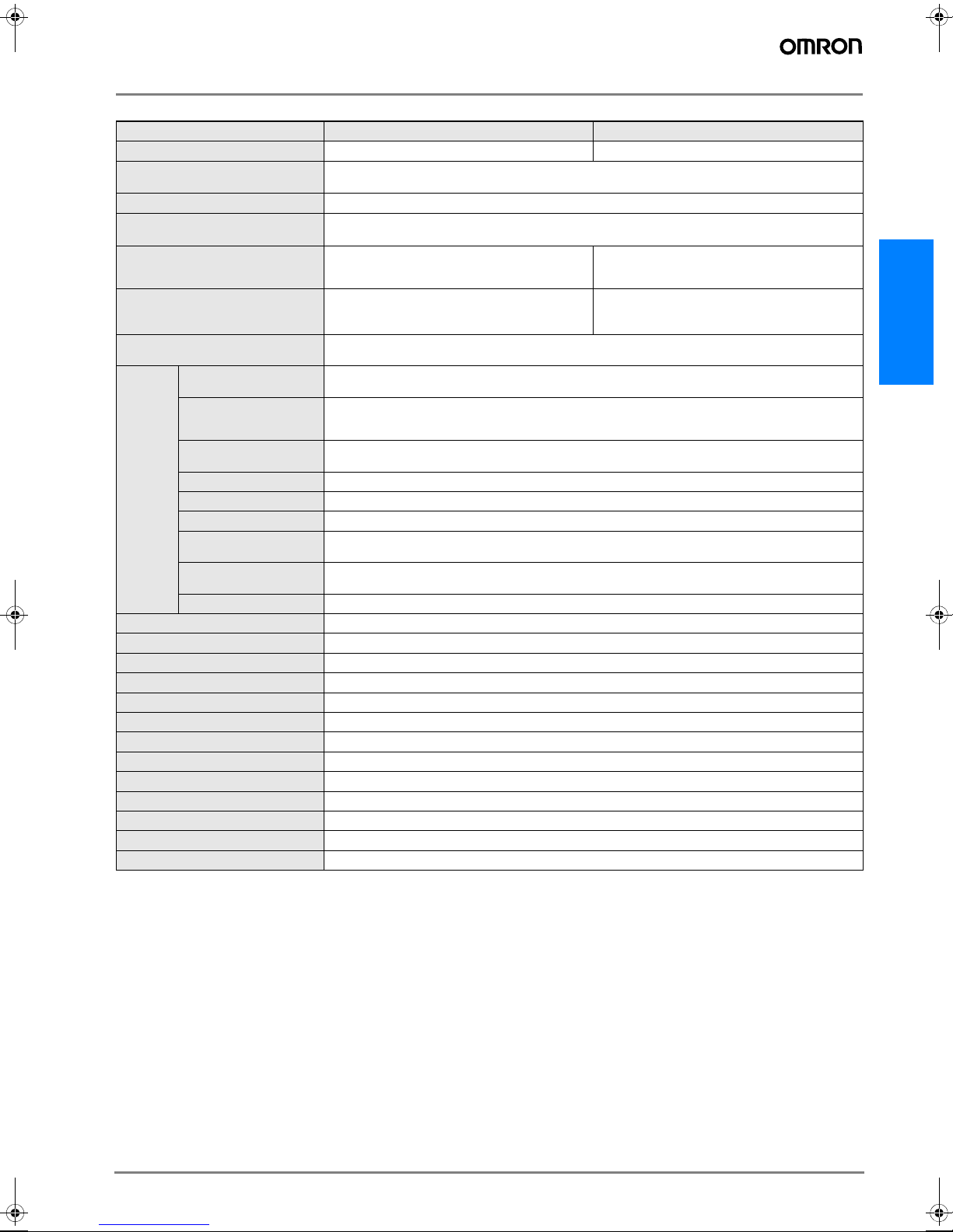
Item ZX-GTC11 ZX-GTC41
Output type NPN PNP
Measurement cycle(*1)
*1: The first response time is "measurement cycle x (number of samples to average setting + 1) + 1 ms" max. For the second response time onwards, the specified measurement cycle time is
output.
1.5 ms (standard mode (NORM))
0.5 ms (high-speed mode (FAST))(*2)
*2: The response time in the high-speed mode (FAST) for the IC lead pitch and IC lead width judgment modes is 1 ms.
Samples to average 1/2/4/8/16/32/64/128/256/512/1024/2048/4096
Analog output(*3)
*3: Current/voltage can be switched using the switch provided on the rear of the Controller.
For current output: 4 to 20 mA/F.S., max. load resistance 300 Ω
For voltage output: ±4 V, (±5 V, 1 to 5 V(*4)), output impedance 100 Ω
*4: Can be set by the analog output scaling function.
Timing input, bank switching input,
zero reset input, reset input
ON: short-circuited with 0V or 1.5V max.
OFF: Open (leakage current: 0.1 mA max.)
ON: short-circuited with power supply voltage or
power supply voltage -1.5V max.
OFF: Open (leakage current: 0.1 mA max.)
HIGH/PASS/LOW
Judgment output(*5)
Sync output(*6)
*5: The error (ERR) state is displayed when all HIGH/PASS/LOW outputs turn OFF.
*6: Normally, wire the sync output wire directly to the emitter's sync input wire and run the Controller in the standard mode. On an NPN type Controller, use an NPN type emitter, and on a PNP
type Controller, use a PNP type emitter. Wiring of the sync wires is not required when the Controller is run in the high-speed mode.
(Note, however, that the Controller becomes more susceptible to the influence of ambient light in this case.)
NPN open-collector output
30 VDC 50 mA max.
Residual voltage 1.2 V max.
PNP open-collector output
30 VDC 50 mA max.
Residual voltage 2 V max.
Indicator Judgment output indicator: HIGH (orange), PASS (green), LOW (orange)
Main display (red) Sub-display (yellow) Bank 1/2 (orange), zero reset (green)
Main
functions
Number of registered
setups
2 banks
Measurement Mode Interrupted beam width measurement, incident beam width measurement, outer diameter measure-
ment, center position measurement, IC lead pitch, IC lead width judgment, specified edge measurement,
wire position measurement, glass edge position measurement
Display during
measurement
Measured value, resolution, threshold, voltage output value, current output value (number of display dig-
its can be changed)
Zero reset functions Offset setting of zero reset value, zero reset value memory
Hold Sample hold, peak hold, bottom hold, peak-to-peak hold, average hold, delay hold
Timer functions ON delay, OFF delay, one-shot
Adjustment functions Optical Axis adjust mode/light intensityt writing mode, variable binary level, variable edge filter, analog
output scaling
Calculation 2 Possible on up to two Controllers (Calculation Unit ZX-CAL2 is required for connecting Controllers to
each other.) A-B, A+B, width
Other Measurement cycle setting, threshold setting, hysteresis setting, initialization, key lock
Temperature characteristic ±0.005%F.S./°C
Current consumption 150 mA max. (including receiver)
Power supply voltage 24 VDC +10%, -15% ripple (p-p) 10% max.
Dielectric strength 1,000 VAC, 50/60 Hz for min
Insulation resistance 20 MΩ(at 500 VDC megger)
Ambient temperature Operating: 0 to +50°C Storage: -15 to +60°C (with no icing or condensation)
Ambient humidity Operating and storage: 35 to 85% (with no condensation)
Vibration resistance(durability) 10 to 150 Hz Single-amplitude: 0.35 mm for 80 min each in X, Y and Z directions
Degree of protection IEC60529 IP20
Cable length 2 m
Material Case: PBT (polybutylene terephthalate), Cover: Polycarbonate
Weight (packed state) Approx. 330 g
Accessories Instruction Sheet
Q20E-EN-01+ZX-GT+Datasheet.fm Seite 3 Montag, 30. Juli 2007 12:01 12