manuals.online logo
Brands
  1. Home
  2. •
  3. Brands
  4. •
  5. Omron
  6. •
  7. Switch
  8. •
  9. Omron ER Series User manual

Omron ER Series User manual

40
2 Mounting Holes Clearance
for M5 Screws
57
46
188 min - 205 max
10
25 139
25
B
74
90
23 57
C
ER5018 ER6022
for M5 Screws
4 Mounting Holes Clearance
10
23
222 min - 239 max
32
7
63
49
40
89
54 86
23
96
4 Mounting Holes Clearance
for M5 Screws
27.50
34
100
96
86
223 min - 240 max
25 60
110
29
10
143
92
ER1022
4 Mounting Holes Clearance
for M5 Screws
27.50
34
100
96
86
327 min - 361 max
25 60
110
29
10
143
92
ER1032
All Dimensions in mm
All Dimensions in mm All Dimensions in mm
All Dimensions in mm
Contact open
Contact closed
2NC 1NO versions
11/12
21/22
33/34
Tension Range Rope Pulled
Rope Slack
3NC versions
11/12
21/22
31/32
Tension Range Rope Pulled
Rope Slack
Rope Slack Rope Slack
Rope Slack
0mm 3.5mm 14.5mm 17.0mm
2NC 1NO versions
11/12
21/22
33/34
Tension Range Rope Pulled
3NC versions
11/12
21/22
31/32
Tension Range Rope Pulled
0mm 4.0mm 14.5mm 17.0mm
4NC 2NO
11/12 41/42
21/22 51/52
32/34 63/64
Tension Range Rope Pulled
0mm 4.0mm 15.0mm 17.0mm
ER5018 ER6022 ER1022 & ER1032
33
21
11
34
22
12
31
21
11
32
22
12
33
21
11
34
22
12
33
21
11
34
22
12
31
21
11
32
22
12
63
51
41
64
52
42
ER Series
Safety,
Technology
& Innovation
Operating Instructions for ER5018, ER6022, ER1022 & ER1032
Installation must be in accordance with the following steps and stated specifications and should be carried out by suitably competent personnel.
Adherence to the recommended maintenance instructions forms part of the warranty.
WARNING: Do not defeat, tamper, remove or bypass this unit. Severe injury to personnel could result.
Red
Green
Black
#1 Terminal #2 Terminal
Optional Indicator Beacon
When +24VDC or 120 VAC (depending on version used) is applied to the red
wire, the beacon will illuminate red and flash.
When +24VDC or 120 VAC (depending on version used) is applied to the
green wire, the beacon will illuminate green and flash. #3 Terminal
Tension Indicator
Indicator shown with steel rope properly adjusted.
1. Installation of all Safety Rope Switch systems must be in accordance with a risk assessment for the
individual application. Installation must only be carried out by competent personnel and in accordance
with these instructions.
2. Rope support eyebolts must be fitted at 2.5m. min. to 3m. max. intervals along all rope lengths
between switches. The rope must be supported no more than 500mm from the switch eyebolt or Safety
Spring (if used). It is important that this first 500mm is not used as part of the active protection coverage.
3. M5 mounting bolts must be used to fix the switches. Tightening torque for mounting bolts to ensure
reliable fixing is 4Nm. Tightening torque for the lid screws, conduit entry plugs and cable glands must be
1.5Nm to ensure IP seal. Only use correct sizing glands for conduit entry and cable outside diameter.
Exclusion of Liability Under the Following Circumstances
- incorrect use
- non-compliance with safety regulations
- installation and electrical connection not performed by authorized
personnel.
- failure to perform functional checks.
EC Declaration of Conformity
The manufacturer named below herewith declares that the product fulfills
the provisions of the directive(s) listed below and that the related standards
have been applied.
OMRON Robotics and Safety Technologies, Inc.
4225 Hacienda Drive, Pleasanton, CA 94588 USA
Directives applied:
Machinery directive 2006/42/EC
RoHS directive 2011/65/EC & 2015/863/EU
Standards applied:
EN 60947-5-1:2017
EN 60947-5-5:1998+/- A2:2017
EN 60204-1:2018
Pleasanton, CA 94588
Hank Liu
Quality Representative and Authorized Signatory
The signed EC Declaration of Conformity is included with the product.
Mechanical Reliability B10d: 1.5 x 10⁶operations at 100mA load
ISO 13849-1: Up to PLe depending upon system architecture
Safety Data - Annual Usage: 8 cycles per hour/24 hours per day/365 days
PFHd: <1.0 x 10⁻⁷
Proof Test Interval (Life): 21 years
MTTFd: 214 years
Enclosure / Cover: Die-cast – painted yellow
External Parts Stainless steel
IP Rating IP67
Rope Spans Max ER1022, ER1032 (heavy duty), dual head 200m.,
single head 125m.
ER6022 (standard duty) = 80m.
ER5018 (mini duty) = 100N
Torque settings Mounting = M5 4.0 Nm
Lid = Torx M4 1.5 Nm
Terminals = 1.0 Nm
Ambient Operating Temperature -25C. to 80 C.
Vibration resistance 10-500Hz 0.35mm
Shock resistance 15g 11ms
Tension Force (typical mid setting) ER1022, ER1032 (Heavy Duty) 130N
ER6022 (standard duty) = 80m.
ER5018 (mini duty) = 100N
Typical Operating Force(Rope pulled) < 125N.< 300mm deflection
Mechanical Life: 1,000,000 operations
Weight ER1022, ER1032 (Heavy Duty) 130N
ER6022 (standard duty) = 80m.
ER5018 (mini duty) = 100N
Electrical
Contact Type: IEC 60947-5-1 Double break Type Zb Snap
Action up to 4NC (Safety positive break_ 2NO
(Auxiliary)
Contact Material: Silver
Termination: Clamp up to 2.5 sq. mm conductors
Approvals: cULus E195653, TUV Typed approved,
Certificate no: 968/EZ 350.02/19
Standards: See EC DofC, UL508 (NKCR, NKCR7)
ER Series
Operating Instructions for ER5018, ER6022, ER1022 & ER1032
4. Tensioning of rope is achieved by use of tensioner / gripper assemblies. Upon installation, tension to mid-position as indicated by the red arrows in the viewing
window of each switch. Check operation for all switches and the control circuits by puling the rope at various locations along the active protection area and resetting each
switch by depressing the Blue Reset button. Ensure each time that the switches latch off and require manual resetting by depressing the Blue Reset button. Increase the
system tension further, if required, depending upon the checks along the active length of coverage. If fitted with a Mushroom type E-Stop button (Red) then test and reset
each switch to ensure function of control circuits. Typical operational conditions for successful operation of system is less than 75N. pulling force and less than 150mm
deflection of rope between eyebolt supports.
5. Every week: Check correct operation of system at locations along all coverage length. Check for nominal tension setting, re-tension rope if necessary. Every 6
months: Isolate power and remove cover. Check screw terminal tightness and check for signs of moisture ingress. Never attempt to repair any switch.
OMRON Robotics and Safety Technologies, Inc.
4225 Hacienda Drive, Pleasanton, CA 94588 USA
www.omron247.com
©2020 All right reserved
Subject to technical modifications
Manual P/N 99918-0010 Rev.D
Information with regard to UL 508
Type 1 enclosures.
Use 16 - 12AWG coper conductors, rated 90°C minimum.
Intended for same polarity use and one polymeric conduit connection.
Electrical rating: A300 240Vac 3A (6,000 cycles).
120V 60A Making 6A. Breaking PF >0.38 (100,000 cycles).
240Vac 10A carry only.
Wire range: 16AWG - 12AWG copper. Torque 7lb/in. (0.8Nm).
LED powered by LVLC or Class 2 only.
Earth bonding terminal inside enclousre.
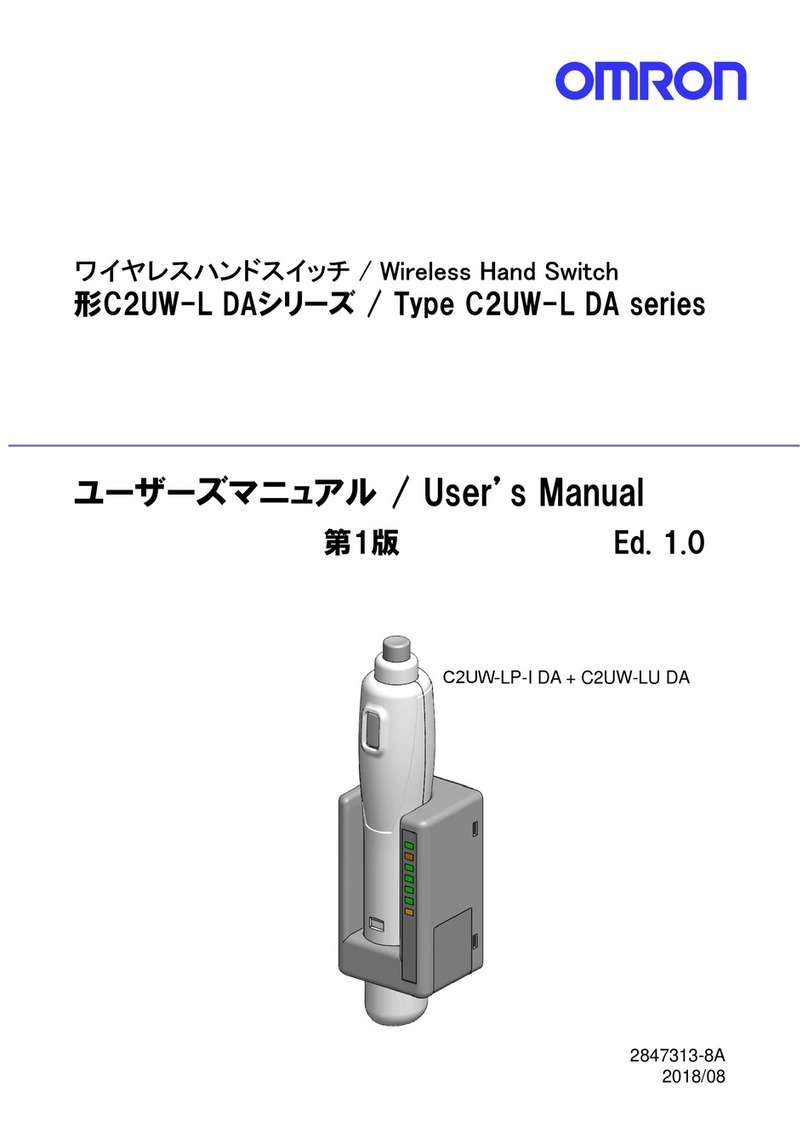
This manual suits for next models

4

Other Omron Switch manuals

Omron D4JL Series User manual

Omron

Omron D4JL Series User manual

Omron XE - User manual

Omron

Omron XE - User manual

Omron D5C Series User manual

Omron

Omron D5C Series User manual

Omron 61F-GP-N User manual

Omron

Omron 61F-GP-N User manual

Omron D4N-R - User manual

Omron

Omron D4N-R - User manual

Omron D4NL-1AFA-B User manual

Omron

Omron D4NL-1AFA-B User manual

Omron D5C User manual

Omron

Omron D5C User manual

Omron D4BL - User manual

Omron

Omron D4BL - User manual

Omron D4N Series User manual

Omron

Omron D4N Series User manual

Omron D2MV User manual

Omron

Omron D2MV User manual

Omron ER6022 User manual

Omron

Omron ER6022 User manual

Omron D40A-G9SX-NS - User manual

Omron

Omron D40A-G9SX-NS - User manual

Omron H5S - User manual

Omron

Omron H5S - User manual

Omron D4DL User manual

Omron

Omron D4DL User manual

Omron S8VS-01505 User manual

Omron

Omron S8VS-01505 User manual

Omron D4BL - User manual

Omron

Omron D4BL - User manual

Omron B3F Manual

Omron

Omron B3F Manual

Omron ZC-55 - User manual

Omron

Omron ZC-55 - User manual

Omron D4JL-1NFA-C5 User manual

Omron

Omron D4JL-1NFA-C5 User manual

Omron HL-5000 - User manual

Omron

Omron HL-5000 - User manual

Omron D4C - User manual

Omron

Omron D4C - User manual

Omron D4F User manual

Omron

Omron D4F User manual

Omron D7E User manual

Omron

Omron D7E User manual

Omron SHL - User manual

Omron

Omron SHL - User manual

Popular Switch manuals by other brands

Bticino 375002 manual

Bticino

Bticino 375002 manual

SilverNet 7 Series user manual

SilverNet

SilverNet 7 Series user manual

Yamaha SFP-SWRG-SX owner's manual

Yamaha

Yamaha SFP-SWRG-SX owner's manual

Belkin OmniView F1DP108G Specifications

Belkin

Belkin OmniView F1DP108G Specifications

H3C S12500X-AF Series Configuration Examples

H3C

H3C S12500X-AF Series Configuration Examples

D-Link KVM-410 - Single Port KVM Switch user manual

D-Link

D-Link KVM-410 - Single Port KVM Switch user manual

Leviton 2653 installation instructions

Leviton

Leviton 2653 installation instructions

NETGEAR M4500 Series installation guide

NETGEAR

NETGEAR M4500 Series installation guide

Intel ICH9 Information guide

Intel

Intel ICH9 Information guide

GRASS VALLEY KAYAK HD Installation and service manual

GRASS VALLEY

GRASS VALLEY KAYAK HD Installation and service manual

nux PML-2 user manual

nux

nux PML-2 user manual

PESA Cougar Series Open Me First

PESA

PESA Cougar Series Open Me First

TP-Link JetStream T1500G-8T user guide

TP-Link

TP-Link JetStream T1500G-8T user guide

WAGO 852-112/000-001 manual

WAGO

WAGO 852-112/000-001 manual

Emerson Rosemount FS-IR-975 Reference manual

Emerson

Emerson Rosemount FS-IR-975 Reference manual

axing SPU 21-02 Operation instructions

axing

axing SPU 21-02 Operation instructions

BZB Gear BG-UHD-KVM41 user manual

BZB Gear

BZB Gear BG-UHD-KVM41 user manual

Banner SI-GL42 Series instruction manual

Banner

Banner SI-GL42 Series instruction manual

manuals.online logo
manuals.online logoBrands
  • About & Mission
  • Contact us
  • Privacy Policy
  • Terms and Conditions

Copyright 2025 Manuals.Online. All Rights Reserved.