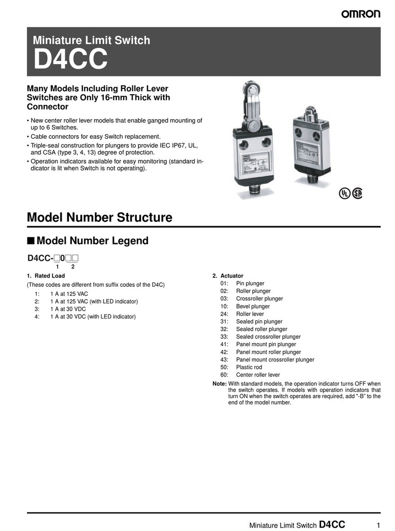
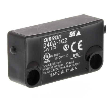
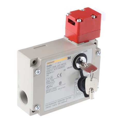
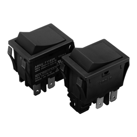
Omron D4SL-N Series User manual

E C
D4SL-N EC
2006/42/EC
EMC 2004/108/EC
( )
IP67
1.5 2
EN IEC60127 4A
(AC125V,1A) 3
9mm
1/2-14NPT
(
(H2S SO2NH3HNO3Cl2)
H2S SO2NH3HNO3Cl2
6
1
LOCK UNLOCK
UNLOCK LOCK
D4SL-N A UNLOCK
D4SL-N G LOCK
UNLOCK
0.2N m
LOCK
0.5 0.6 N m
0.4 0.5 N m
D4SL-NK G 0.75 1.15 N m
D4SL-NK NK S 2.4 2.8 N m
0.75 1.15 N m
1.8 2.2 N m G1/2 M20
1.4 1.8 N m 1/2-14NPT
2
M4
4±0.1 1.5
(D4SL-NK )
0.8mm
3
D4SL-K
3
4
5
NC
DC24V E1 E2
DC24V
6
.
AWG22 18 0.3 0.75mm2
PHOENIX
CONTACT
AI0.34-8 TQ AWG22
AI0.5-8 WH AWG20
AI0.75-8 GY AWG18
1/2-14NPT IP67
9mm
9mm
IP67
G1/2
LAPP ST-PF1/2 5380-1002 6.0 12.0mm
LS-2G
6.0 11.0mm
M20 LAPP ST-M20×1.5 5311-1020 7.0 13.0mm
1/2-14NPT LAPP ST-NPT1/2 5301-6030 6.0 12.0mm
JPK-16 GPM20
LAPP TEL 043 423 8741
http://www.ace-service.co.jp
1/2-14NPT
EMC EN1088 EN50047 GS-ET-19
EN60947-5-1 IEC60947-5-1, UL508 CSA C22.2 No.14
EN
AC-15 DC-13
AC120V DC125V
1.5A 0.22A
UL CSA
C150 R150
AC120V DC125V
1800VA 28VA
180VA 28VA
( ) 15mm
( ) 60N
1300N GS-ET-19
0.05 1m/s
5 /
100A
4A (IEC60127)
IP67(EN60947-5-1) ( IP00)
TYPE 4X INDOOR USE ONLY (UL, CSA)
DC5V 1mA ( )
10 55 ( )
95 RH
100
15 (AC125 1A )
DC24V+10 /-15
-
D4SL-N |N/P/Q/R| - 6.4W-0.27A
D4SL-N | | - 4.8W-0.2A
2.6W 0.15A
(LED) DC24V 10mA
B10d 2,000,000
ON/OFF
a)
b)
c)
d) 24
e)
*
0120-919-066
PHS
055-982-5015
8 00 21 00 365
FA
055-977-6389
9 00 12 00/13 00 17 30
FAX
FAX 055-982-5051
Original instruction
EC Declaration of Conformity
OMRON declares that D4SL-N is in conformity with the requirements of the
following EC Directives:
Machinery Directive 2006/42/EC
EMC Directive 2004/108/EC
Safety Precaution
Definition of Precautionary Information
Indicates an imminently hazardous situation
which, if not avoided, is likely to result in serious
injury or may result in death. Additiona
lly there
may be severe property damage.
Indicates a potentially hazardous situation
which, if not avoided, may result in minor or
moderate injury or in property damage.
Precautionary Information
DANGER
Always verify the operation of the safety functions
before starting the system.Not do so may result that
the safety functions may not be performed as expected
if wiring or settings are incorrect or the switch have
failed.The controlled system may continue to operate
and possibly resulting in injury or death.
CAUTION
Do not dismount the operation key from the door
intentionally and insert it to the switch with the door
open. Machine may start operating and injury or death
may be caused.
Do not apply force exceeding the specified maximum
holding force. Doing so may damage the switch lock
mechanism and the system may continue to operate,
possibly resulting in injury or death. Either install another
locking component (e.g., a hook) in addition to the
Switch, or use a warning measures or an indicator
showing the controlled system is locked to avoid
overloading the holding force in lock mode.
Precautions for Safe Use
1. Environment
1-1. Do not use the switch where explosive gas, ignitable gas, or any other harmful
gasses may be present.
1-2. Do not use the switch in the oil and in the water. IP67 (EN60947-5-1)
1-3. Though the switch body is protected from the ingress of dust or water, avoid
the ingress of foreign substance through the key hole on the head.
Otherwise, wear in short time or break may be caused
2. Wiring
2-1. Connect the fuse to the switch in series to prevent it from short circuit damage.
The value of the breaking current of the fuse must be increased to cover the
rated current by 150 to 200%. When using the switch with EN rating, use 4 A
fast acting fuse that complies with IEC 60127.
2-2. On the switching of general loads (125VAC/1A), do not operate three circuits or
more at the same time. Otherwise, insulation performance may be degraded.
2-3. Keep the electrical load below the rated value.
2-4.Use a metallic connector which has a threaded portion of 9 mm length or less.
2-5. Do not use metal conduit with this switch. The broken conduit hole may cause
electrical shock hazard.
2-6.Use of a 1/2-14NPT connector may result in damage to a conversion adapter,
causing defective sealing or a risk of electric shock. Do not use metallic
connectors.
2-7. Be sure to install a cover after the wiring.
Do not put the electric power when opening a cover.
Do not put the electric power when wiring.
2-8. Makesurethatforeignsubstance doesnotadhereto theboard.. Ashort-circuitbetweenboard
terminalsmayoccur,causingthesafetyfunctionsdisabled.
3. Mounting
3-1. Be careful not to drop your D4SL-N, or the switch will
not fully exhibit its ability.
3-2. This may cause a risk of personal injury.
Extra care must be taken not to drop this Product
during installation..
3-3. Install operation key so that it will not hit the operator
when the door is open. Injury may be caused.
3-4.Do not use the switch as a stopper.
Be sure to install a stopper as shown in the following
illustration to prevent the edge of the operation key
from inadvertently hitting the switch directly.
4. Others
4-1. Do not disassemble or remodel your D4SL-N in any case, or the D4SL-N will
not operate normally.
4-2. Evaluate the switch under actual working conditions before permanent
installation.
The durability of the switch is seriously affected by operating conditions.
4-3. Please mention in machine manufacturer’s Instruction.
Manual that the user must not repair nor maintain the switch and must
contact machine manufacturer for them.
Precautions for Correct Use
1. About the solenoid lock type
1-1. Be sure to energize the solenoid with the door closed (with the operation key
inserted). A malfunction will occur in Solenoid lock when energizing the
solenoid before closing the door.
1-2. In the solenoid lock type, a lock is closed only when the solenoids are energized.
A lock may be opened when the passage of an electric current to the solenoid is
stopped due to sudden power failure. Do not use the solenoid lock type for the
machine in which the inside of the door remains dangerous even after
shutdown of the machine.
2. Environment
2-1. The switch is intended for indoor use only.
2-2. Do not use your D4SL-N outdoor, or the switch will malfunction.
2-3. Do not use your D4SL-N in the atmosphere of hazardous gases (H2S, SO2, NH3,
HNO3, CI2, etc.) or high temperature and humidity, or it will cause the
imperfect closing of the contacts or the breakage thereof stemming from
corrosion.
2-4. Do not use the switch under any of the conditions mentioned below.
Frequent temperature range.
High humidity or dew condensation may be generated.
Where the switch is subject to severe vibration.
Where the metal dust, oil, or chemical is sprayed inside the door.
Where thinner is applied.
3. Storage
3-1. Do not keep the switch in dusty, humid place and any place where gas may be
present for example H2S, SO2, NH3, HNO3, Cl2..
3-2. A switch that has been stored for more than six months must be checked again
before use.
4. Using the release key (See Figure 1)
4-1. The release key is used to open a lock in the case of power failure or
emergency.
4-2. Turn the release key from the LOCK position to the UNLOCK position to
release the lock. This can open the safety door. (For the mechanical lock type
only.)
4.3. When the release key is turned to the UNLOCK position for maintenance or
other purposes, make sure to turn it back to the LOCK position before using it.
4-4. The set position of the release key at the shipping of the switch is as noted
below;
D4SL-N A : UNLOCK position D4SL-N G : LOCK position
4-5. While the release key is in the UNLOCK position, a lock is not closed and a
machine is not activated even when the door is closed in the course of
preliminary adjustment work performed inside a large ma chine or a
depressing type machine.
4-6. Do not use the release key when starting or stopping the machine.
4-7. The releasing of the auxiliary lock must be handled by an authorized person.
4-8. Do not apply an excessive force (of 0.2N m or more) to the threaded portion of
the release key. The release key may be damaged to the extent that it no
longer becomes operational.
4-9. To avoid an unauthorized person's access to the release mechanism, set the
release key to the LOCK position, and then seal the release key with a seal
wax (or wax coatings).
5. Installing the cover
5-1. Confirm that the seal rubber has no abnormality and then use it.
If the seal rubber is displaced or floated, or if foreign matters adhere to the seal
rubber, the seal rubber will lose its sealing capability.
5-2. Do not use any screw other than correct one, or the sealing capability of the
seal rubber will deteriorate.
6. About the hinge type door
6-1. A door is mounted near a hinge, excessive load may be imposed beyond a force
acting on the lock portion of this Equipment. This may result in damage to the
lock mechanism. Mount it to a position near a handle.
7. Mounting method
7-1. Mounting screw tightening torque loose mounting may result in malfunction.
Fasten the screws to the specified torque.
Terminal screw
0.5 to 0.6 N m
Cover clamping screw
0.4 to 0.5 N m
Operation key clamping screw (D4SL-NK G
0.75 to 1.15 N m
Operation key clamping screw
(D4SL-NK ,NK S)
2.4 to 2.8 N m
Body clamping screw
0.75 to 1.15N m
Conduit mounting connection
1.8 to 2.2 N m (G1/2,M20)
1.4 to 1.8 N m (1/2-14NPT)
7-2. Switch, operation key (See Figure 2)
1) The switch and operation key will be fastened to specified torque in clause 7-1
with M4 screws and washers.
2) The switch can be fastened more firmly by a stud(4mm dia., 1.5mm max height)
inserted from back side at the hole of the switch.
3) Do not use the operation key other than dedicated OMRON’s (D4SL-NK ).
Otherwise switch may be damaged.
4) Be sure that the operation key can be inserted properly to key hole with a
tolerance of ±0.8mm.
5) Insert the operation key into the key hole according to the specified “operation
key insertion radius in horizontal direction”.
6) Do not impose excessive force on the key top while the operation key is inserted
into the switch body or drop the switch with the operation key inserted to avoid
the deformation of the key or the breakage of the switch body.
7) When mounting at the side of switch body, mount the switch with 3 points
including the head.
8) Attach cap heads to any operation key holes that are not being used.
9) Do not use the operation key D4SL-K . A lock will not be closed and a machine
will not be activated.
7-3. Securing of the door (See Figure 3)
1) If the operation key is pulled in the opening direction due to a force caused by
vibration, by the door weight, or by a cushion attached to the door. The closed
door must be secured with a hook or by similar means.
7-4. Spacer (See Figure 4)
1) Do not remove the spacer. Use the switch with the spacer rotated appropriate
for the mounting direction. Lock strength will decrease when using the switch
without spacer.
8. Wiring
8-1. Example of circuit connections (See Figure 5)
1). Internal circuit of the switch inside is different according to the part
number. Please confirm the circuit diagram on the product body when
using.
2). The open circuit operating contacts are labeled with arrow marks. They are
able to used as input to the safety circuit.
3). Please make the system that can observe both the door open/close
detection switch and the lock monitor switch NC contacts close when
the lock is necessary on safety.
4). The 24VDC solenoid has a polarity. (E1: Positive (+) polarity, E2: Negative ( -)
polarity)
5). Current consumption of the solenoid is different in inrush and constant.
Apply the rated working voltage to the solenoid.
8-2. Wiring (See Figure 6)
1). Do not put the electric power when wiring.
2). Do not let particles such as small piece of lead wire in the switch body when
wiring.
3). Install the wiring through a crimp-style terminal for an insulating tube so that
the wires do not run over the case or cover.
4). Adequate conductor size is AWG 22 to 18 (0.3 to 0.75mm2).
5). Wire leads as shown in the following figure. Otherwise, the switch cover does
not fit.
6). When wiring the D4SL-N, remove the terminal block board out of the D4SL-N.
After this, make sure to insert the connector.
7). Do not pull on lead wires with excessive force. The wires may break.
Recommended Crimp-Style Terminals
Manufacturer
Type
Adequate cable
PHOENIX
CONTACT
AI0.34-8 TQ
AWG22
AI0.5-8 WH
AWG20
AI0.75-8 GY
AWG18
L1 max. 14mm
L2 max. 8mm
9. Conduit opening
1). Use the connectors recommended in clause 10 and tighten the connector with
specified torque in clause 7-1. An excessive torque will bring a case breakage.
2). When using the connector size of 1/2-14NPT, apply the sealing tape between
connector and conduit opening so that the enclosure will conform to IP67.
3). Use a cable with a suitable diameter for the connector.
10. Recommendation of connector
For easy wiring, use a connector that has the screw part with 9 mm or less in
length.
Use below listed connector to secure IP67.
Size Manufacturer Type
Adequate cable
Diameter
G1/2
LAPP
ST-PF1/2 5380-1002
6.0 to 12.0 mm
ACE
SERVICE
LS-2G
(Short type)
6.0 to 11.0 mm
M20
LAPP
ST-M20
×
1.5
5311-1020
7.0 to 13.0 mm
1/2-14NPT
LAPP
ST-NPT1/2 5301-6030
6.0 to 12.0 mm
Use an optional seal packing (Type: JPK-16 or GPM20).
Tighten the seal packing to a proper tightening torque.
LAPP is a German manufacturer.
Ace Service is a Japanese manufacturer.
Before a connector of 1/2-14NPT size is used, install a supplied conversion
adapter on the switch and wrap it in seal tape.
11. Others
11-1. Please do a regular check in premeditation for this switch
12. Technical specification
Conformity : Machine Directive, Low Voltage Directive, EMC Directive,
EN1088 EN50047,GS-ET-19
Approval EN60947-5-1 IEC60947-5-1 UL508 CSA
C22.2 No.14
EN electrical rating
Utilization category AC-15/DC-13
Rated Voltage 120VAC / 125VDC
Rated Current 1.5A / 0.22A
UL, CSA electrical rating
C150 R150
Voltage 120VAC 125VDC
Volt Amp. Make 1800VA 28VA
Break 180VA 28VA
Overvoltage Category
Direct opening travel (min.) 15 mm
Direct opening force (min.) 60 N
Holding force (min.) 1300N (GS-ET-19)
Operating speed 0.05 to 1 m/s
Operating frequency 5 operation / minute max.
Conditional short-circuit current 100A
Short circuit protective device Use 4 A fast acting fuse in accordance with
IEC 60127
Enclosure rating IP67 (EN60947-5-1) (Operation key insertion face : IP00)
TYPE 4X INDOOR USE ONLY (UL, CSA)
Minimum permissible load:5VDC,1mA resistive load (N level : reference value)
Ambient temperature range -10 to +55
(Protect against Frost)
Ambient humidity (max.):95%RH
Mechanical durability (min.) 1,000,000 operations
Electrical durability (min.) 150,000 operations
(125VAC,1A resistive load)
Solenoid Rated working voltage 24VDC+10%/-15%
Power-Current consumption
Inrush
D4SL-N |N/P/Q/R | -Approximately 6.4W-0.27A
D4SL-N |A/B/C/D/E/F/G/H/S/T/U/V | -
Approximately 4.8W-0.2A
Constant Approximately 2.6W-0.15A (max.)
Indicator lamp(LED) Rated voltage 24VDC
Current consumption Approximately 10mA
B10d : 2,000,000
There is no equality between the ON/OFF motions of a contact.
The switch contacts are common use for general load and micro load but, after
switching a general load, it is impossible to switch a micro load with the same
contacts. The contact reliability would be decrease due to the rough contact
surface.
Liability for use in safety systems
OMRON shall not be responsible for conformity with any standards, codes, or
regulations that apply to the combination of the products in the customer's
application or use of the product.
Take all necessary steps to determine the suitability of the product for the systems,
machines, and equipment with which it will be used.
Know and observe all prohibitions of use applicable to this product.
NEVER USE THE PRODUCTS FOR AN APPLICATION INVOLVING SERIOUS
RISK TO LIFE OR PROPERTY WITHOUT ENSURING THAT THE SYSTEM AS
A WHOLE HAS BEEN DESIGNED TO ADDRESS THE RISKS, AND THAT THE
OMRON PRODUCT IS PROPERLY RATED AND INSTALLED FOR THE
INTENDED USE WITHIN THE OVERALL EQUIPMENT OR SYSTEM.
See also Product catalog for Warranty and Limitation of Liability.
OMRON Corporation Industrial Automation Company
OMRON EUROPE B.V.
Wegalaan 67-69-2132 JD Hoofddorp The Netherlands
Tel: (31)2356-81-300 / Fax: (31)2356-81-388
OMRON ASIA PACIFIC PTE. LTD.
No. 438A Alexandra Road # 05-05/08 (Lobby 2),Alexandra Technopark, Singapore
119967
Tel: (65) 6835-3011 / Fax: (65) 6835-2711
OMRON SCIENTIFIC TECHNOLOGIES INC.
6550 Dumbarton Circle, Fremont CA 94555-3605 U.S.A.
Tel: (1) 510-608-3400 / Fax: (1) 510-744-1442
OMRON (CHINA) CO., LTD.
Room 2211, Bank of China Tower, 200 Yin Cheng Zhong Road,PuDong New Area,
Shanghai, 200120, China
Tel: (86) 21-5037-2222 / Fax: (86) 21-5037-2200
Traceability Information
Representative in EU
OMRON EUROPE B.V.
Wegalann 67-69 2132 JD Hoofddorp
The Netherlands
Manufacturer
OMRON CORPORATION, Safety Device Division
Shiokoji Horikawa, Shimogyo-ku, Kyoto, 600-8530JAPAN
L1 14mm
L2 8mm
Guard Lock Safety-door Switch
Manvel d’Instrvctions
Instruction Sheet manuale d’Instruzioni
Bertriebsanleitung manuale de Instrucciones
CAUTION
Thank you for purchasing this D4SL-N. This INSTRUCTION MANUAL described the information such as
function, performance and how to use the product required for using the D4SL-N.
For using this product, please follow keep the precautions as shown in the following:
Ensure that this product is installed and operated by qualified personal having sufficient skills in
mechanics and electrotechnic.
Ensure that you understood this manual and that you use the product as described in this manual.
Keep this instruction manual close at hand and use it for reference during operation.
2219498-9 A
EU EU www.industrial.omron.eu/safety.
Instructions in the official EU languages and a signed EC Declaration of Conformity in English are available on our website at www.industrial.omron.eu/safety.
DANGER
E1
()
21
33
11
22
34
42
52
51
E2
()
12
41
64 63
7
3
1
10
8
4
2
9
5
6
for D4SL-N N -D
LED
Lock Monitor Switch)
To Safety Circuit
To Control Circuit
To Safety Circuit
Door Open/Clos
e
Detection Switch)
To Control Circuit
E1
()
21
31
22
32
42
E2
( )
41
62 61
7
3
1
10
8
4
2
9
5
6
for D4SL-N V
Lock Monitor Switch)
To Control Circuit
To Safety Circuit
Door Open/Close
Detection Switch)
To Control Circuit
AND
D4SL-N -
D4SL-N - 4
LOCK
UNLOCK
LOCK
UNLOCK
D4SL-NK3
D4SL-NK1G/-NK2G
D4SL-NK1/-NK1S/-NK2
6 Fig.6
M4
Front
4±0.1 dia. 1.5mm high max
22±0.1
41.7±0.15
Side
22±0.1
38.7±0.1
10±0.1
41.7±0.15
M4
4±0.1 dia. 1.5mm high max
1 Fig.1
3 Fig.3
5 Fig.5
4 Fig.4
2 Fig.2
13579
246810
2-M4
15
±
0.1
2-M4
40
±
0.1
2-M4
12
±
0.1
or 20±0.1
Head
Original instruction
OMRON declares that D4SL-N is in conformity with the requirements of the
following EC Directives:
Machinery Directive 2006/42/EC
EMC Directive 2004/108/EC
1. Environment
1-1. Do not use the switch where explosive gas, ignitable gas, or any other harmful
gasses may be present.
1-2. Do not use the switch in the oil and in the water. IP67 (EN60947-5-1)
1-3. Though the switch body is protected from the ingress of dust or water, avoid
the ingress of foreign substance through the key hole on the head.
Otherwise, wear in short time or break may be caused
2. Wiring
2-1. Connect the fuse to the switch in series to prevent it from short circuit damage.
The value of the breaking current of the fuse must be increased to cover the
rated current by 150 to 200%. When using the switch with EN rating, use 4 A
fast acting fuse that complies with IEC 60127.
2-2. On the switching of general loads (125VAC/1A), do not operate three circuits or
more at the same time. Otherwise, insulation performance may be degraded.
2-3. Keep the electrical load below the rated value.
2-4.Use a metallic connector which has a threaded portion of 9 mm length or less.
2-5. Do not use metal conduit with this switch. The broken conduit hole may cause
electrical shock hazard.
2-6.Use of a 1/2-14NPT connector may result in damage to a conversion adapter,
causing defective sealing or a risk of electric shock. Do not use metallic
connectors.
2-7. Be sure to install a cover after the wiring.
Do not put the electric power when opening a cover.
Do not put the electric power when wiring.
2-8. Makesurethatforeignsubstance doesnotadhere totheboard.. Ashort-circuitbetweenboard
terminalsmayoccur,causingthesafetyfunctionsdisabled.
3. Mounting
3-1. Be careful not to drop your D4SL-N, or the switch will
not fully exhibit its ability.
3-2. This may cause a risk of personal injury.
Extra care must be taken not to drop this Product
during installation..
3-3. Install operation key so that it will not hit the operator
when the door is open. Injury may be caused.
3-4.Do not use the switch as a stopper.
Be sure to install a stopper as shown in the following
illustration to prevent the edge of the operation key
from inadvertently hitting the switch directly.
4. Others
4-1. Do not disassemble or remodel your D4SL-N in any case, or the D4SL-N will
not operate normally.
4-2. Evaluate the switch under actual working conditions before permanent
installation.
The durability of the switch is seriously affected by operating conditions.
4-3. Please mention in machine manufacturer’s Instruction.
Manual that the user must not repair nor maintain the switch and must
contact machine manufacturer for them.
1. About the solenoid lock type
1-1. Be sure to energize the solenoid with the door closed (with the operation key
inserted). A malfunction will occur in Solenoid lock when energizing the
solenoid before closing the door.
1-2. In the solenoid lock type, a lock is closed only when the solenoids are energized.
A lock may be opened when the passage of an electric current to the solenoid is
stopped due to sudden power failure. Do not use the solenoid lock type for the
machine in which the inside of the door remains dangerous even after
shutdown of the machine.
2. Environment
2-1. The switch is intended for indoor use only.
2-2. Do not use your D4SL-N outdoor, or the switch will malfunction.
2-3. Do not use your D4SL-N in the atmosphere of hazardous gases (H2S, SO2, NH3,
HNO3, CI2, etc.) or high temperature and humidity, or it will cause the
imperfect closing of the contacts or the breakage thereof stemming from
corrosion.
2-4. Do not use the switch under any of the conditions mentioned below.
Frequent temperature range.
High humidity or dew condensation may be generated.
Where the switch is subject to severe vibration.
Where the metal dust, oil, or chemical is sprayed inside the door.
Where thinner is applied.
3. Storage
3-1. Do not keep the switch in dusty, humid place and any place where gas may be
present for example H2S, SO2, NH3, HNO3, Cl2..
3-2. A switch that has been stored for more than six months must be checked again
before use.
4. Using the release key (See Figure 1)
4-1. The release key is used to open a lock in the case of power failure or
emergency.
4-2. Turn the release key from the LOCK position to the UNLOCK position to
release the lock. This can open the safety door. (For the mechanical lock type
only.)
4.3. When the release key is turned to the UNLOCK position for maintenance or
other purposes, make sure to turn it back to the LOCK position before using it.
4-4. The set position of the release key at the shipping of the switch is as noted
below;
D4SL-N A : UNLOCK position D4SL-N G : LOCK position
4-5. While the release key is in the UNLOCK position, a lock is not closed and a
machine is not activated even when the door is closed in the course of
preliminary adjustment work performed inside a large machine or a
depressing type machine.
4-6. Do not use the release key when starting or stopping the machine.
4-7. The releasing of the auxiliary lock must be handled by an authorized person.
4-8. Do not apply an excessive force (of 0.2N m or more) to the threaded portion of
the release key. The release key may be damaged to the extent that it no
longer becomes operational.
4-9. To avoid an unauthorized person's access to the release mechanism, set the
release key to the LOCK position, and then seal the release key with a seal
wax (or wax coatings).
5. Installing the cover
5-1. Confirm that the seal rubber has no abnormality and then use it.
If the seal rubber is displaced or floated, or if foreign matters adhere to the seal
rubber, the seal rubber will lose its sealing capability.
5-2. Do not use any screw other than correct one, or the sealing capability of the
seal rubber will deteriorate.
6. About the hinge type door
6-1. A door is mounted near a hinge, excessive load may be imposed beyond a force
acting on the lock portion of this Equipment. This may result in damage to the
lock mechanism. Mount it to a position near a handle.
7. Mounting method
7-1. Mounting screw tightening torque loose mounting may result in malfunction.
Fasten the screws to the specified torque.
N6.0ot5.0wercslanimreT m
N5.0ot4.0wercsgnipmalcrevoC m
Operation key clamping screw (D4SL-NK G 0.75 to 1.15 N m
Operation key clamping screw
(D4SL-NK ,NK S) 2.4 to 2.8 N m
Body clamping screw 0.75 to 1.15N m
1.8 to 2.2 N m (G1/2,M20)
Conduit mounting connection 1.4 to 1.8 N m (1/2-14NPT)
7-2. Switch, operation key (See Figure 2)
1) The switch and operation key will be fastened to specified torque in clause 7-1
with M4 screws and washers.
2) The switch can be fastened more firmly by a stud(4mm dia., 1.5mm max height)
inserted from back side at the hole of the switch.
3) Do not use the operation key other than dedicated OMRON’s (D4SL-NK ).
Otherwise switch may be damaged.
4) Be sure that the operation key can be inserted properly to key hole with a
tolerance of 0.8mm.
5) Insert the operation key into the key hole according to the specified “operation
key insertion radius in horizontal direction”.
6) Do not impose excessive force on the key top while the operation key is inserted
into the switch body or drop the switch with the operation key inserted to avoid
the deformation of the key or the breakage of the switch body.
7) When mounting at the side of switch body, mount the switch with 3 points
including the head.
8) Attach cap heads to any operation key holes that are not being used.
9) Do not use the operation key D4SL-K . A lock will not be closed and a machine
will not be activated.
7-3. Securing of the door (See Figure 3)
1) If the operation key is pulled in the opening direction due to a force caused by
vibration, by the door weight, or by a cushion attached to the door. The closed
door must be secured with a hook or by similar means.
7-4. Spacer (See Figure 4)
1) Do not remove the spacer. Use the switch with the spacer rotated appropriate
for the mounting direction. Lock strength will decrease when using the switch
without spacer.
8. Wiring
8-1. Example of circuit connections (See Figure 5)
1). Internal circuit of the switch inside is different according to the part
number. Please confirm the circuit diagram on the product body when
using.
2). The open circuit operating contacts are labeled with arrow marks. They are
able to used as input to the safety circuit.
3). Please make the system that can observe both the door open/close
detection switch and the lock monitor switch NC contacts close when
the lock is necessary on safety.
4). The 24VDC solenoid has a polarity. (E1: Positive (+) polarity, E2: Negative (-)
polarity)
5). Current consumption of the solenoid is different in inrush and constant.
Apply the rated working voltage to the solenoid.
8-2. Wiring (See Figure 6)
1). Do not put the electric power when wiring.
2). Do not let particles such as small piece of lead wire in the switch body when
wiring.
3). Install the wiring through a crimp-style terminal for an insulating tube so that
the wires do not run over the case or cover.
4). Adequate conductor size is AWG 22 to 18 (0.3 to 0.75mm 2).
5). Wire leads as shown in the following figure. Otherwise, the switch cover does
not fit.
6). When wiring the D4SL-N, remove the terminal block board out of the D4SL-N.
After this, make sure to insert the connector.
7). Do not pull on lead wires with excessive force. The wires may break.
Recommended Crimp-Style Terminals
Manufacturer Type Adequate cable
AI0.34-8 TQ AWG22
AI0.5-8 WH AWG20
PHOENIX
CONTACT AI0.75-8 GY AWG18
L1 max. 14mm
L2 max. 8mm
9. Conduit opening
1). Use the connectors recommended in clause 10 and tighten the connector with
specified torque in clause 7-1. An excessive torque will bring a case breakage.
2). When using the connector size of 1/2-14NPT, apply the sealing tape between
connector and conduit opening so that the enclosure will conform to IP67.
3). Use a cable with a suitable diameter for the connector.
10. Recommendation of connector
For easy wiring, use a connector that has the screw part with 9 mm or less in
length.
Use below listed connector to secure IP67.
Size Manufacturer Type Adequate cable
Diameter
LAPP ST-PF1/2 5380-1002 6.0 to 12.0 mm
G1/2 ACE
SERVICE
LS-2G
(Short type) 6.0 to 11.0 mm
M20 LAPP ST-M20 1.5 5311-1020 7.0 to 13.0 mm
1/2-14NPT LAPP ST-NPT1/2 5301-6030 6.0 to 12.0 mm
Use an optional seal packing (Type: JPK-16 or GPM20).
Tighten the seal packing to a proper tightening torque.
LAPP is a German manufacturer.
Ace Service is a Japanese manufacturer.
Before a connector of 1/2-14NPT size is used, install a supplied conversion
adapter on the switch and wrap it in seal tape.
11. Others
11-1. Please do a regular check in premeditation for this switch
12. Technical specification
Conformity : Machine Directive, Low Voltage Directive, EMC Directive,
EN1088 EN50047,GS-ET-19
Approval EN60947-5-1 IEC60947-5-1 UL508 CSA C22.2 No.14
EN electrical rating
Utilization category AC-15/DC-13
Rated Voltage 120VAC / 125VDC
Rated Current 1.5A / 0.22A
UL, CSA electrical rating
C150 R150
Voltage 120VAC 125VDC
Volt Amp. Make 1800VA 28VA
Break 180VA 28VA
Overvoltage Category
Direct opening travel (min.) 15 mm
Direct opening force (min.) 60 N
Holding force (min.) 1300N (GS-ET-19)
Operating speed 0.05 to 1 m/s
Operating frequency 5 operation / minute max.
Conditional short-circuit current 100A
Short circuit protective device Use 4 A fast acting fuse in accordance with
IEC 60127
Enclosure rating IP67 (EN60947-5-1) (Operation key insertion face : IP00)
TYPE 4X INDOOR USE ONLY (UL, CSA)
Minimum permissible load:5VDC,1mA resistive load (N level : reference value)
Ambient temperature range -10 to +55 (Protect against Frost)
Ambient humidity (max.):95%RH
Mechanical durability (min.) 1,000,000 operations
Electrical durability (min.) 150,000 operations (125VAC,1A resistive load)
Solenoid Rated working voltage 24VDC+10%/-15%
Power-Current consumption
Inrush
D4SL-N |N/P/Q/R | - Approximately 6.4W-0.27A
D4SL-N |A/B/C/D/E/F/G/H/S/T/U/V | -
Approximately 4.8W-0.2A
Constant Approximately 2.6W-0.15A (max.)
Indicator lamp(LED) Rated voltage 24VDC
Current consumption Approximately 10mA
B10d : 2,000,000
There is no equality between the ON/OFF motions of a contact.
The switch contacts are common use for general load and micro load but, after
switching a general load, it is impossible to switch a micro load with the same
contacts. The contact reliability would be decrease due to the rough contact
surface.
OMRON shall not be responsible for conformity with any standards, codes, or
regulations that apply to the combination of the products in the customer's
application or use of the product.
Take all necessary steps to determine the suitability of the product for the systems,
machines, and equipment with which it will be used.
Know and observe all prohibitions of use applicable to this product.
NEVER USE THE PRODUCTS FOR AN APPLICATION INVOLVING SERIOUS
RISK TO LIFE OR PROPERTY WITHOUT ENSURING THAT THE SYSTEM AS
A WHOLE HAS BEEN DESIGNED TO ADDRESS THE RISKS, AND THAT THE
OMRON PRODUCT IS PROPERLY RATED AND INSTALLED FOR THE
INTENDED USE WITHIN THE OVERALL EQUIPMENT OR SYSTEM.
See also Product catalog for Warranty and Limitation of Liability.
OMRON EUROPE B.V.
Wegalaan 67-69-2132 JD Hoofddorp The Netherlands
Tel: (31)2356-81-300 / Fax: (31)2356-81-388
OMRON ASIA PACIFIC PTE. LTD.
No. 438A Alexandra Road # 05-05/08 (Lobby 2),Alexandra Technopark, Singapore
119967
Tel: (65) 6835-3011 / Fax: (65) 6835-2711
OMRON SCIENTIFIC TECHNOLOGIES INC.
6550 Dumbarton Circle, Fremont CA 94555-3605 U.S.A.
Tel: (1) 510-608-3400 / Fax: (1) 510-744-1442
OMRON (CHINA) CO., LTD.
Room 2211, Bank of China Tower, 200 Yin Cheng Zhong Road,PuDong New Area,
Shanghai, 200120, China
Tel: (86) 21-5037-2222 / Fax: (86) 21-5037-2200
Representative in EU
OMRON EUROPE B.V.
Wegalann 67-69 2132 JD Hoofddorp
The Netherlands
Manufacturer
OMRON CORPORATION, Safety Device Division
Shiokoji Horikawa, Shimogyo-ku, Kyoto, 600-8530JAPAN
Thank you for purchasing this D4SL-N. This INSTRUCTION MANUAL described the information such as
function, performance and how to use the product required for using the D4SL-N.
For using this product, please follow keep the precautions as shown in the following:
Ensure that this product is installed and operated by qualified personal having sufficient skills in
mechanics and electrotechnic.
Ensure that you understood this manual and that you use the product as described in this manual.
Keep this instruction manual close at hand and use it for reference during operation.
E1
()
21
33
11
22
34
42
52 51
E2
()
1241
64 63
for D4SL-N N -D
LED
Lock Monitor Switch)
To Safety Circuit
To Safety Circuit
Door Open/Clos
e
Detection Switch)
E1
()
21
31
22
32
42
E2
()
41
62 61
for D4SL-N V
Lock Monitor Switch)
To Safety Circuit
Door Open/Clos
e
Detection Switch)
6 Fig.6
1 Fig.1 3 Fig.3 5 Fig.5
4 Fig.4
2 Fig.2
±
±
±
E C
D4SL-N EC
2006/42/EC
EMC 2004/108/EC
( )
IP67
1.5 2
EN IEC60127 4A
(AC125V,1A) 3
9mm
1/2-14NPT
(
(H2S SO2NH3HNO3Cl2)
H2S SO2NH3HNO3Cl2
6
1
LOCK UNLOCK
UNLOCK LOCK
D4SL-N A UNLOCK
D4SL-N G LOCK
UNLOCK
0.2N m
LOCK
0.5 0.6 N m
0.4 0.5 N m
D4SL-NK G 0.75 1.15 N m
D4SL-NK NK S 2.4 2.8 N m
0.75 1.15 N m
1.8 2.2 N m G1/2 M20
1.4 1.8 N m 1/2-14NPT
2
M4
4±0.1 1.5
(D4SL-NK )
0.8mm
3
D4SL-K
3
4
5
NC
DC24V E1 E2
DC24V
6
.
AWG22 18 0.3 0.75mm2
PHOENIX
CONTACT
AI0.34-8 TQ AWG22
AI0.5-8 WH AWG20
AI0.75-8 GY AWG18
1/2-14NPT IP67
9mm
9mm
IP67
G1/2
LAPP ST-PF1/2 5380-1002 6.0 12.0mm
LS-2G
6.0 11.0mm
M20 LAPP ST-M20×1.5 5311-1020 7.0 13.0mm
1/2-14NPT LAPP ST-NPT1/2 5301-6030 6.0 12.0mm
JPK-16 GPM20
LAPP TEL 043 423 8741
http://www.ace-service.co.jp
1/2-14NPT
EMC EN1088 EN50047 GS-ET-19
EN60947-5-1 IEC60947-5-1, UL508 CSA C22.2 No.14
EN
AC-15 DC-13
AC120V DC125V
1.5A 0.22A
UL CSA
C150 R150
AC120V DC125V
1800VA 28VA
180VA 28VA
( ) 15mm
( ) 60N
1300N GS-ET-19
0.05 1m/s
5 /
100A
4A (IEC60127)
IP67(EN60947-5-1) ( IP00)
TYPE 4X INDOOR USE ONLY (UL, CSA)
DC5V 1mA ( )
10 55 ( )
95 RH
100
15 (AC125 1A )
DC24V+10 /-15
-
D4SL-N |N/P/Q/R| - 6.4W-0.27A
D4SL-N | | - 4.8W-0.2A
2.6W 0.15A
(LED) DC24V 10mA
B10d 2,000,000
ON/OFF
a)
b)
c)
d) 24
e)
*
0120-919-066
PHS
055-982-5015
8 00 21 00 365
FA
055-977-6389
9 00 12 00/13 00 17 30
FAX
FAX 055-982-5051
Original instruction
EC Declaration of Conformity
OMRON declares that D4SL-N is in conformity with the requirements of the
following EC Directives:
Machinery Directive 2006/42/EC
EMC Directive 2004/108/EC
Safety Precaution
Definition of Precautionary Information
Indicates an imminently hazardous situation
which, if not avoided, is likely to result in serious
injury or may result in death. Additiona
lly there
may be severe property damage.
Indicates a potentially hazardous situation
which, if not avoided, may result in minor or
moderate injury or in property damage.
Precautionary Information
DANGER
Always verify the operation of the safety functions
before starting the system.Not do so may result that
the safety functions may not be performed as expected
if wiring or settings are incorrect or the switch have
failed.The controlled system may continue to operate
and possibly resulting in injury or death.
CAUTION
Do not dismount the operation key from the door
intentionally and insert it to the switch with the door
open. Machine may start operating and injury or death
may be caused.
Do not apply force exceeding the specified maximum
holding force. Doing so may damage the switch lock
mechanism and the system may continue to operate,
possibly resulting in injury or death. Either install another
locking component (e.g., a hook) in addition to the
Switch, or use a warning measures or an indicator
showing the controlled system is locked to avoid
overloading the holding force in lock mode.
Precautions for Safe Use
1. Environment
1-1. Do not use the switch where explosive gas, ignitable gas, or any other harmful
gasses may be present.
1-2. Do not use the switch in the oil and in the water. IP67 (EN60947-5-1)
1-3. Though the switch body is protected from the ingress of dust or water, avoid
the ingress of foreign substance through the key hole on the head.
Otherwise, wear in short time or break may be caused
2. Wiring
2-1. Connect the fuse to the switch in series to prevent it from short circuit damage.
The value of the breaking current of the fuse must be increased to cover the
rated current by 150 to 200%. When using the switch with EN rating, use 4 A
fast acting fuse that complies with IEC 60127.
2-2. On the switching of general loads (125VAC/1A), do not operate three circuits or
more at the same time. Otherwise, insulation performance may be degraded.
2-3. Keep the electrical load below the rated value.
2-4.Use a metallic connector which has a threaded portion of 9 mm length or less.
2-5. Do not use metal conduit with this switch. The broken conduit hole may cause
electrical shock hazard.
2-6.Use of a 1/2-14NPT connector may result in damage to a conversion adapter,
causing defective sealing or a risk of electric shock. Do not use metallic
connectors.
2-7. Be sure to install a cover after the wiring.
Do not put the electric power when opening a cover.
Do not put the electric power when wiring.
2-8. Makesurethatforeignsubstance doesnotadheretotheboard.. Ashort-circuitbetweenboard
terminalsmayoccur,causing the safety functionsdisabled.
3. Mounting
3-1. Be careful not to drop your D4SL-N, or the switch will
not fully exhibit its ability.
3-2. This may cause a risk of personal injury.
Extra care must be taken not to drop this Product
during installation..
3-3. Install operation key so that it will not hit the operator
when the door is open. Injury may be caused.
3-4.Do not use the switch as a stopper.
Be sure to install a stopper as shown in the following
illustration to prevent the edge of the operation key
from inadvertently hitting the switch directly.
4. Others
4-1. Do not disassemble or remodel your D4SL-N in any case, or the D4SL-N will
not operate normally.
4-2. Evaluate the switch under actual working conditions before permanent
installation.
The durability of the switch is seriously affected by operating conditions.
4-3. Please mention in machine manufacturer’s Instruction.
Manual that the user must not repair nor maintain the switch and must
contact machine manufacturer for them.
Precautions for Correct Use
1. About the solenoid lock type
1-1. Be sure to energize the solenoid with the door closed (with the operation key
inserted). A malfunction will occur in Solenoid lock when energizing the
solenoid before closing the door.
1-2. In the solenoid lock type, a lock is closed only when the solenoids are energized.
A lock may be opened when the passage of an electric current to the solenoid is
stopped due to sudden power failure. Do not use the solenoid lock type for the
machine in which the inside of the door remains dangerous even after
shutdown of the machine.
2. Environment
2-1. The switch is intended for indoor use only.
2-2. Do not use your D4SL-N outdoor, or the switch will malfunction.
2-3. Do not use your D4SL-N in the atmosphere of hazardous gases (H2S, SO2, NH3,
HNO3, CI2, etc.) or high temperature and humidity, or it will cause the
imperfect closing of the contacts or the breakage thereof stemming from
corrosion.
2-4. Do not use the switch under any of the conditions mentioned below.
Frequent temperature range.
High humidity or dew condensation may be generated.
Where the switch is subject to severe vibration.
Where the metal dust, oil, or chemical is sprayed inside the door.
Where thinner is applied.
3. Storage
3-1. Do not keep the switch in dusty, humid place and any place where gas may be
present for example H2S, SO2, NH3, HNO3, Cl2..
3-2. A switch that has been stored for more than six months must be checked again
before use.
4. Using the release key (See Figure 1)
4-1. The release key is used to open a lock in the case of power failure or
emergency.
4-2. Turn the release key from the LOCK position to the UNLOCK position to
release the lock. This can open the safety door. (For the mechanical lock type
only.)
4.3. When the release key is turned to the UNLOCK position for maintenance or
other purposes, make sure to turn it back to the LOCK position before using it.
4-4. The set position of the release key at the shipping of the switch is as noted
below;
D4SL-N A : UNLOCK position D4SL-N G : LOCK position
4-5. While the release key is in the UNLOCK position, a lock is not closed and a
machine is not activated even when the door is closed in the course of
preliminary adjustment work performed inside a large ma chine or a
depressing type machine.
4-6. Do not use the release key when starting or stopping the machine.
4-7. The releasing of the auxiliary lock must be handled by an authorized person.
4-8. Do not apply an excessive force (of 0.2N m or more) to the threaded portion of
the release key. The release key may be damaged to the extent that it no
longer becomes operational.
4-9. To avoid an unauthorized person's access to the release mechanism, set the
release key to the LOCK position, and then seal the release key with a seal
wax (or wax coatings).
5. Installing the cover
5-1. Confirm that the seal rubber has no abnormality and then use it.
If the seal rubber is displaced or floated, or if foreign matters adhere to the seal
rubber, the seal rubber will lose its sealing capability.
5-2. Do not use any screw other than correct one, or the sealing capability of the
seal rubber will deteriorate.
6. About the hinge type door
6-1. A door is mounted near a hinge, excessive load may be imposed beyond a force
acting on the lock portion of this Equipment. This may result in damage to the
lock mechanism. Mount it to a position near a handle.
7. Mounting method
7-1. Mounting screw tightening torque loose mounting may result in malfunction.
Fasten the screws to the specified torque.
Terminal screw
0.5 to 0.6 N m
Cover clamping screw
0.4 to 0.5 N m
Operation key clamping screw (D4SL-NK G
0.75 to 1.15 N m
Operation key clamping screw
(D4SL-NK ,NK S)
2.4 to 2.8 N m
Body clamping screw
0.75 to 1.15N m
Conduit mounting connection
1.8 to 2.2 N m (G1/2,M20)
1.4 to 1.8 N m (1/2-14NPT)
7-2. Switch, operation key (See Figure 2)
1) The switch and operation key will be fastened to specified torque in clause 7-1
with M4 screws and washers.
2) The switch can be fastened more firmly by a stud(4mm dia., 1.5mm max height)
inserted from back side at the hole of the switch.
3) Do not use the operation key other than dedicated OMRON’s (D4SL-NK ).
Otherwise switch may be damaged.
4) Be sure that the operation key can be inserted properly to key hole with a
tolerance of ±0.8mm.
5) Insert the operation key into the key hole according to the specified “operation
key insertion radius in horizontal direction”.
6) Do not impose excessive force on the key top while the operation key is inserted
into the switch body or drop the switch with the operation key inserted to avoid
the deformation of the key or the breakage of the switch body.
7) When mounting at the side of switch body, mount the switch with 3 points
including the head.
8) Attach cap heads to any operation key holes that are not being used.
9) Do not use the operation key D4SL-K . A lock will not be closed and a machine
will not be activated.
7-3. Securing of the door (See Figure 3)
1) If the operation key is pulled in the opening direction due to a force caused by
vibration, by the door weight, or by a cushion attached to the door. The closed
door must be secured with a hook or by similar means.
7-4. Spacer (See Figure 4)
1) Do not remove the spacer. Use the switch with the spacer rotated appropriate
for the mounting direction. Lock strength will decrease when using the switch
without spacer.
8. Wiring
8-1. Example of circuit connections (See Figure 5)
1). Internal circuit of the switch inside is different according to the part
number. Please confirm the circuit diagram on the product body when
using.
2). The open circuit operating contacts are labeled with arrow marks. They are
able to used as input to the safety circuit.
3). Please make the system that can observe both the door open/close
detection switch and the lock monitor switch NC contacts close when
the lock is necessary on safety.
4). The 24VDC solenoid has a polarity. (E1: Positive (+) polarity, E2: Negative ( -)
polarity)
5). Current consumption of the solenoid is different in inrush and constant.
Apply the rated working voltage to the solenoid.
8-2. Wiring (See Figure 6)
1). Do not put the electric power when wiring.
2). Do not let particles such as small piece of lead wire in the switch body when
wiring.
3). Install the wiring through a crimp-style terminal for an insulating tube so that
the wires do not run over the case or cover.
4). Adequate conductor size is AWG 22 to 18 (0.3 to 0.75mm2).
5). Wire leads as shown in the following figure. Otherwise, the switch cover does
not fit.
6). When wiring the D4SL-N, remove the terminal block board out of the D4SL-N.
After this, make sure to insert the connector.
7). Do not pull on lead wires with excessive force. The wires may break.
Recommended Crimp-Style Terminals
Manufacturer
Type
Adequate cable
PHOENIX
CONTACT
AI0.34-8 TQ
AWG22
AI0.5-8 WH
AWG20
AI0.75-8 GY
AWG18
L1 max. 14mm
L2 max. 8mm
9. Conduit opening
1). Use the connectors recommended in clause 10 and tighten the connector with
specified torque in clause 7-1. An excessive torque will bring a case breakage.
2). When using the connector size of 1/2-14NPT, apply the sealing tape between
connector and conduit opening so that the enclosure will conform to IP67.
3). Use a cable with a suitable diameter for the connector.
10. Recommendation of connector
For easy wiring, use a connector that has the screw part with 9 mm or less in
length.
Use below listed connector to secure IP67.
Size Manufacturer Type
Adequate cable
Diameter
G1/2
LAPP
ST-PF1/2 5380-1002
6.0 to 12.0 mm
ACE
SERVICE
LS-2G
(Short type)
6.0 to 11.0 mm
M20
LAPP
ST-M20
×
1.5
5311-1020
7.0 to 13.0 mm
1/2-14NPT
LAPP
ST-NPT1/2 5301-6030
6.0 to 12.0 mm
Use an optional seal packing (Type: JPK-16 or GPM20).
Tighten the seal packing to a proper tightening torque.
LAPP is a German manufacturer.
Ace Service is a Japanese manufacturer.
Before a connector of 1/2-14NPT size is used, install a supplied conversion
adapter on the switch and wrap it in seal tape.
11. Others
11-1. Please do a regular check in premeditation for this switch
12. Technical specification
Conformity : Machine Directive, Low Voltage Directive, EMC Directive,
EN1088 EN50047,GS-ET-19
Approval EN60947-5-1 IEC60947-5-1 UL508 CSA
C22.2 No.14
EN electrical rating
Utilization category AC-15/DC-13
Rated Voltage 120VAC / 125VDC
Rated Current 1.5A / 0.22A
UL, CSA electrical rating
C150 R150
Voltage 120VAC 125VDC
Volt Amp. Make 1800VA 28VA
Break 180VA 28VA
Overvoltage Category
Direct opening travel (min.) 15 mm
Direct opening force (min.) 60 N
Holding force (min.) 1300N (GS-ET-19)
Operating speed 0.05 to 1 m/s
Operating frequency 5 operation / minute max.
Conditional short-circuit current 100A
Short circuit protective device Use 4 A fast acting fuse in accordance with
IEC 60127
Enclosure rating IP67 (EN60947-5-1) (Operation key insertion face : IP00)
TYPE 4X INDOOR USE ONLY (UL, CSA)
Minimum permissible load:5VDC,1mA resistive load (N level : reference value)
Ambient temperature range -10 to +55
(Protect against Frost)
Ambient humidity (max.):95%RH
Mechanical durability (min.) 1,000,000 operations
Electrical durability (min.) 150,000 operations
(125VAC,1A resistive load)
Solenoid Rated working voltage 24VDC+10%/-15%
Power-Current consumption
Inrush
D4SL-N |N/P/Q/R | -Approximately 6.4W-0.27A
D4SL-N |A/B/C/D/E/F/G/H/S/T/U/V | -
Approximately 4.8W-0.2A
Constant Approximately 2.6W-0.15A (max.)
Indicator lamp(LED) Rated voltage 24VDC
Current consumption Approximately 10mA
B10d : 2,000,000
There is no equality between the ON/OFF motions of a contact.
The switch contacts are common use for general load and micro load but, after
switching a general load, it is impossible to switch a micro load with the same
contacts. The contact reliability would be decrease due to the rough contact
surface.
Liability for use in safety systems
OMRON shall not be responsible for conformity with any standards, codes, or
regulations that apply to the combination of the products in the customer's
application or use of the product.
Take all necessary steps to determine the suitability of the product for the systems,
machines, and equipment with which it will be used.
Know and observe all prohibitions of use applicable to this product.
NEVER USE THE PRODUCTS FOR AN APPLICATION INVOLVING SERIOUS
RISK TO LIFE OR PROPERTY WITHOUT ENSURING THAT THE SYSTEM AS
A WHOLE HAS BEEN DESIGNED TO ADDRESS THE RISKS, AND THAT THE
OMRON PRODUCT IS PROPERLY RATED AND INSTALLED FOR THE
INTENDED USE WITHIN THE OVERALL EQUIPMENT OR SYSTEM.
See also Product catalog for Warranty and Limitation of Liability.
OMRON Corporation Industrial Automation Company
OMRON EUROPE B.V.
Wegalaan 67-69-2132 JD Hoofddorp The Netherlands
Tel: (31)2356-81-300 / Fax: (31)2356-81-388
OMRON ASIA PACIFIC PTE. LTD.
No. 438A Alexandra Road # 05-05/08 (Lobby 2),Alexandra Technopark, Singapore
119967
Tel: (65) 6835-3011 / Fax: (65) 6835-2711
OMRON SCIENTIFIC TECHNOLOGIES INC.
6550 Dumbarton Circle, Fremont CA 94555-3605 U.S.A.
Tel: (1) 510-608-3400 / Fax: (1) 510-744-1442
OMRON (CHINA) CO., LTD.
Room 2211, Bank of China Tower, 200 Yin Cheng Zhong Road,PuDong New Area,
Shanghai, 200120, China
Tel: (86) 21-5037-2222 / Fax: (86) 21-5037-2200
Traceability Information
Representative in EU
OMRON EUROPE B.V.
Wegalann 67-69 2132 JD Hoofddorp
The Netherlands
Manufacturer
OMRON CORPORATION, Safety Device Division
Shiokoji Horikawa, Shimogyo-ku, Kyoto, 600-8530JAPAN
L1 14mm
L2 8mm
Guard Lock Safety-door Switch
Manvel d’Instrvctions
Instruction Sheet manuale d’Instruzioni
Bertriebsanleitung manuale de Instrucciones
CAUTION
Thank you for purchasing this D4SL-N. This INSTRUCTION MANUAL described the information such as
function, performance and how to use the product required for using the D4SL-N.
For using this product, please follow keep the precautions as shown in the following:
Ensure that this product is installed and operated by qualified personal having sufficient skills in
mechanics and electrotechnic.
Ensure that you understood this manual and that you use the product as described in this manual.
Keep this instruction manual close at hand and use it for reference during operation.
2219498-9 A
EU EU www.industrial.omron.eu/safety.
Instructions in the official EU languages and a signed EC Declaration of Conformity in English are available on our website at www.industrial.omron.eu/safety.
DANGER
E1
()
21
33
11
22
34
42
52
51
E2
()
12
41
64
63
7
3
1
10
8
4
2
9
5
6
for D4SL-N N -D
LED
Lock Monitor Switch)
To Safety Circuit
To Control Circuit
To Safety Circuit
Door Open/Close
Detection Switch)
To Control Circuit
E1
()
21
31
22
32
42
E2
()
41
62
61
7
3
1
10
8
4
2
9
5
6
for D4SL-N V
Lock Monitor Switch)
To Control Circuit
To Safety Circuit
Door Open/Close
Detection Switch)
To Control Circuit
AND
D4SL-N -
D4SL-N - 4
LOCK
UNLOCK
LOCK
UNLOCK
D4SL-NK3
D4SL-NK1G/-NK2G
D4SL-NK1/-NK1S/-NK2
6 Fig.6
M4
Front
4±0.1 dia. 1.5mm high max
22±0.1
41.7±0.15
Side
22±0.1
38.7±0.1
10±0.1
41.7±0.15
M4
4±0.1 dia. 1.5mm high max
1 Fig.1
3 Fig.3
5 Fig.5
4 Fig.4
2 Fig.2
1
3
5
7
9
2
4
6
8
10
2-M4
15
±
0.1
2-M4
40
±
0.1
2-M4
12
±
0.1
or 20±0.1
Head

WICHTIGE SICHERHEITSHINWEISE
Definitionder Sicherheitsinformationen
VORSICHT
Weist auf eine mögliche Gefährdungssituation hin, die
bei Missachtung kleine, mittelschwere Verletzungen oder
Sachschäden hervorrufen kann.
Sicherheitsinformationen
GEFAHR
ÜberprüfenSiestetsdieFunktionderSicherheitsvorrichtungen,bevorSiedasSystem
in Betrieb nehmen. Wird diese Überprüfung nicht durchgeführt, besteht die Gefahr,
dass die Sicherheitsvorrichtungen nicht wie erwartet arbeiten, wenn die Verdrahtung
oder Einstellungen fehlerhaft sind oder die Schalter ausgefallen sind. Das gesteuerte
System setzt dadurch seinen Betrieb möglicherweise in einer Gefahrensituation fort,
waszuVerletzungenoderzumTodführenkann.
VORSICHT
"Stecken Sie den Betätiger nicht bei geöffneter Tür in den Schalter. Dadurch kann die
Maschineunerwartetanlaufen."
Wenden Sie keine Kraft an, die die spezifizierte maximale Zuhaltekraft übersteigt.
AndernfallsbestehtdieGefahreinerBeschädigungdesVerriegelungsmechanismusund
dasSystem setztseinenBetrieb möglicherweisein einerGefahrensituationfort,waszu
Verletzungen oder zum Tod führen kann Installieren Sie entweder eine weitere
Verriegelungseinrichtung (z. B. einen Riegel) zusätzlich zum Schalter oder verwenden
SieeineWarnmethodeoderAnzeige,durchdieabgezeigtwird,dassdasSystemgesperrt
ist, damit keine Kräfte angewendet werden, die die Zuhaltekraft im verriegelten
Zustandübersteigen.
Sicherheitsmaßnahmen
1. VorsichtsmaßnahmenfürdensicherenGebrauch
2. Es besteht Verletzungsgefahr.DasProdukt beimAnbringennicht fallenlassen.
3. LassenSiedasProdukt aufkeinenFallfallen, sonstkanneszu Funktionsstörungen desSchalterskommen.
4. Demontieren Siedas Produktauf keinen Fall oderbauen Sie esum.Hierdurch kann es zu Funktionsstörungen kommen.
5. Verwenden Sie den Schalter nicht an Orten, wo explosive, entzündliche oder andere schädliche Gase vorhanden sein
können.
6. Installieren Sie den Betätiger so, dass er das Bedienungspersonal nicht berühren kann, während die Tür geöffnet oder
geschlossenwird.DadurchkönnenVerletzungenhervorgerufenwerden.
7. "Verwenden Sie das Produkt nicht in Wasser, in Öl oder an Orten, wo es mit Wasser oderÖl in Berührung kommen kann.
WasseroderÖl könnenindas Produkteindringen.
(Der Schalter entspricht der Schutzart IP67, was bedeutet, dass er für einen bestimmten Zeitraum wasserdicht geblieben
ist, nachdem er insWassergelegtwurde.)"
8.Im Fall derNutzung vonMetallverbindungsstückendarfdieGewindelänge9mm nichtüberschreiten.
9. Wird ein 1/2-14 NPT-Stecker verwendet, kann es bei Beschädigung des Adapters zu einer Verschlechterung der
Schließeigenschaften undzuStromschlagkommen. BitteverwendenSiekeineMetallsteckeroder–rohrverbindungen.
10."Obwohldas Schaltergehäuse gegen das Eindringenvon Staub oder Wasser geschützt ist,vermeidenSie dassFremdkörper
durchdieBetätigerlöffnung eindringen.
Andernfallskannes innerhalbkurzer Zeit zustarkemVerschleißoderAusfallkommen. "
11. SchaltenSiedieStromversorgungnichtein,währendSiedie Verdrahtung vornehmen.
12."Achten Sie unbedingtdarauf, nachderVerdrahtungdieAbdeckungwieder zuschließen.
Schalten Sie die Stromversorgung nicht ein, wenn Sie die Abdeckung öffnen. Es besteht die
GefahreineselektrischenSchlages."
13. Um den Schalter vor Kurzschluss zu schützen, muss eine Sicherung vorgeschaltet werden.Die
Sicherungmussaufdas1,5 bis 2-fachedesNennstroms dimensioniertwerden.
VerwendenSiebitte eine4AflinkeSicherunggemäß IEC60127, wenn SieeinenEN-Schalterverwenden.
14.Schalten Sie bei normaler Belastung (125VAC/1A) nicht gleichzeitigmehr als dreiStromkreise einund aus.
Es kann sein,dass sich dieIsolations-Funktionverschlechtert.
15.DieLebensdauerdesSchalterswirdinerheblichemMaßevondenBetriebsbedingungenbeeinflusst.
PrüfenSiedaherdenSchalteruntertatsächlichenBetriebsbedingungenundhaltenSiedievorgeschriebene
HäufigkeitderSchaltzyklenein.
16.Wartungbzw.Instandsetzungdes SchaltersdürfennichtvomAnwendervorgenommenwerden.
WendenSie sich in diesemFallan den Hersteller.
17.BitteachtenSiedarauf, dassamKlemmenblockundander Leiterplattekeine Fremdkörperhaftenbleiben.
Es kann sein,dass beiKlemm-KurzschlussdieSicherheit beeinträchtigt ist.
REGLES DE SECURITE
Significationdes avertissements
PRECAUTION
Une utilisation incorrecte de ce produit pourrait
donner lieu à des blessures de moindre ou moyenne
gravité et à des dégâts matériels.
Avertissements
DANGER
Vérifiez toujours le fonctionnement des dispositifs de sécurité avant le démarrage du
système. Le non-respect de cette règle peut entraîner le fonctionnement incorrect des
dispositifs de sécurité si le câblage ou les paramètres sont incorrects ou en cas de
défaillance des commutateurs. Il se peut que le système commandé continue à
fonctionner,provoquantdesblessuresoulamort.
PRECAUTION
Ceproduitpeuts’actionneretprovoquerdesdégâts.Nepasinsérerlacléd’actionnement
quandlaporteestouverte.
N'appliquez pas une force supérieure à la force de maintien maximale spécifiée. Le
non-
respect de cette règle peut endommager le mécanisme de verrouillage du
commutateur et il se peut que le système continue à fonctionner, provoquant des
blessuresoulamort.Installezplutôtunautresystèmedeverrouillage(parexempleun
dispositif d'arrêt) en plus du commutateur, ou utilisez une méthode ou un panneau
d'avertissementpourindiquerquelesystèmecommandéestverrouilléafind'éviterune
forcedemaintientropimportanteenmodedeverrouillage.
Precaution d'usage pour la sécurité
1. Il sepeutquelecommutateurnefonctionnepaspleinement.Nefaitespastomberle produit.
2. Risquedeblessure.Lorsdel'installation del'appareil,veillez àcequ’ilnetombe pas.
3. Nedémonteroutrafiquer ce produit enaucuncas.Celapourraitempêcher sonfonctionnementnormal.
4. Nepas utiliserceproduitdansunenvironnementàgazexplosif,gazinflammableetc.
5. Installer la clé d’actionnement de sorte qu’elle ne vienne pas au contact de l’opérateur à l’ouverture/fermeture de la porte.
Des blessuressontpossibles.
6. Nepas utiliserleproduitdansdel’huileoudel’eau,oudansunemplacement oùilpourraitàtoutmomentêtresoumis àdes
éclaboussuresd’huileoud’eau.Del’eauoudel’huilepourraitpénétreràl’intérieur.
(Le dispositif de protection IP67 contrôle la pénétration d’eau si ce commutateur est laissé dans l’eau pendant un certain
temps.)
7. Le commutateur lui-même est protégé contre la pénétration de la poussière ou de l’eau, mais éviter la pénétration de
matières étrangèresdansletroud’insertionde la cléd’actionnement de la tête.Celapourrait provoquer uneusureprécoce ou
desdégâts.
8. Lorsqu’un connecteur métallique est utilisé, ce dernier doit avoir une partie filetée d’une longueur inférieure ou égale à
9mm.
9. Lorsdel'utilisation du connecteur½-14NPT, il ya un risque demauvaise isolationqui peut survenir àlasuite de la rupture
de l'adaptateur, ainsiqueduchocélectrique. Nepasutiliserdeconnecteurs nidecâblesmétalliques.
10.Nepasmettresoustensionlorsducâblage. Uneélectrocution seraitpossible.
11. Ne pas oublier d’installer le couvercle après le câblage. Ne pas mettre sous tension quand le couvercle est ouvert. Une
électrocutionserait possible.
12.Connecterlecommutateur ensérie àunfusible à courantderupturede 1,5à2 fois supérieur
au courant nominalpouréviter lesdommages dusà un court-circuitducircuit.
En casd'utilisationavecunecatégorie EN,veuillezutiliserdesfusibles à fusion
ultra-rapideconformémentau standard IEC60127.
13.Pourl'ouvertureet lafermeturedechargeordinaire(125VAC, 1A), nepasactionner3circuitsou
plus en même temps,ou lacapacité d'isolationrisqueraitdes'entrouverréduite.
14.Ladurabilitéducommutateurestfortementinfluencéeparlesconditions defonctionnement.
Vérifierlecommutateurdansles conditionsdefonctionnementréelleset l’utiliser dans des l
imitesneposant pasdeproblèmes.
15.L’utilisateur doit faireappel àunagentdeservicedufabricantpourlaréparationet l’entretien,
et nepasles effectuer lui-même.
16.Nepasutilisercecommutateurcommeretenue. Nepasinstallerderetenue,commeindiquésur
l’illustration,pourquelapartie collierdelacléd’actionnementneheurtepaslatête.
17.Veuillezvousassurerqu'aucunélémentcollantnegènelebornierdeconnexion ainsiquelecircuitimprimé.
Lesterminauxpeuventcourt-circuiterentre eux etengendrer desproblèmessurlefonctionnementnormaldusystème
de sécurité.
PRECAUZIONI PER LASICUREZZA
Significato delleindicazioni di avvertenza
ATTENZIONE
Una operazione non corretta può anche causare, data
la sua potenziale pericolosità, ferite leggere o di medio
grado, oppure danni al materiale.
Indicazionediavvertenza
PERICOLO
Verificare sempre il funzionamento delle funzioni di sicurezza prima di avviare il
sistema. In caso contrario, le funzioni di sicurezza potrebbero non funzionare come
previstoseilcablaggiooleimpostazioninonsonocorretteoinpresenzadiunguastodel
finecorsa. Il sistema controllato potrebbe quindi continuare a funzionare ponendo in
gravepericolol'incolumitàdell'operatore(rischiodilesioniomorte).
ATTENZIONE
Non inserire la chiave di azionamento quando la porta di protezione è
aperta. L' apparecchio può iniziare a funzionare, causando danni fisici.
Non applicare una forza superiorealla forza di ritenzione massimaspecificata. In caso
contrario, il meccanismo di blocco del finecorsa potrebbe danneggiarsi e il sistema
potrebbe continuare a funzionare ponendo in grave pericolo l'incolumità dell'operatore
(rischiodilesioniomorte).Installareundispositivodibloccoaggiuntivooltrealfinecorsa,
adesempiounfermo,oppureutilizzareunaspiaounmessaggiodiavvisopersegnalare
ilbloccodelsistemacontrollato,alfinedievitareilsuperamentodellaforzadiritenzione
inmodalitàdiblocco.
Precauzioni per l'utilizzo in condizioni di sicurezza
1. Non far cadereilprodotto.Il finecorsa potrebbero funzionare nondebitamente.
2. C'èilrischio disubiredannifisici. Prestareladovuta attenzionepernonfar cadereilprodottonelmomentodelfissaggio.
3. Non effettuare alcuno smontaggio o modifica del prodotto per nessuna ragione. Potrebbe pregiudicare il suo regolare
funzionamento.
4. Nonadoperareilprodottoin ambientiincui visiagasesplosivoo infiammabile.
5. Collocare la chiave di azionamento in una zona in cui la chiave stessa non possa toccare il corpo dell’operatore nel momento
dell’apertura e dellachiusuradellaporta diprotezione.Essapotrebbeanche causare feriteallepersone.
6. Nonadoporareilprodottoinacquaodinolioe neppure inambienti chepossonoesseresemprebagnati dall’acqua odall’olio.
L’acqua e l’olio possono penetrare all’interno del prodotto. (La struttura protettiva IP67 del finecorsa accerta l’infiltrazione di
acqua in casoche lapermanenzanell’acqua siprotraeperun determinatotempo).
7. Il finecorsastesso èprotettodapenetrazionedipolvereo di acqua, purtuttaviabisognaprestare moltaattenzione ache non
si infiltrino corpi estranei dentro il foro per l’inserimento della chiave di azionamento della zona dellatestata. Leinfiltrazioni
possonoessereunadellecause delsuodeterioramentoprematuroodellasuarottura.
8.Qualorasiadoperaunconnettore metallico, utilizzarne unola cuivitenonsuperilalunghezzadi9mm.
9. L’uso di un connettore 1/2-14NPT può causare danni all’adattatore di conversione rendendo le guarnizioni difettose e
generandoilrischio discaricheelettriche.Non utilizzarenéconnettorimetallici,nétubimetallici.
10.Nondarealimentazioneduranteilcollegamentodeifili. Ci potrebbe essereilrischio di scosseelettriche.
11. Dopo aver terminato il lavoro di collegamento dei fili montare sempre la copertura primadi procedere alsuo utilizzo. Non
attaccarelatensione conlacopertura aperta.Ci potrebbeessereilrischio discosseelettriche.
12.Perevitarecheil finecorsasirompaacausadicortocircuito,inserire,inserie alfinecorsa,
un fusibileconilvalore diinterruzione di 1,5a2voltepiù del valorenominale.
Quandosiutilizzaun interruttoreditipoEN,utilizzareun fubiledi tipo 4A(interruzione rapida),
compatibileconIEC60127.
13.All'apertura/chiusura di carichigenerali(125VAC, 1A) ,non utilizzarepiù di 3circuiti alla volta.
La proprietàisolante potrebbe esserecompromessa.
14.Laresistenzadelfinecorsa variaconilvariaredellecondizioni dell’apertura/chiusura.Perprocedere
al suoregolareutilizzo,provareilprodotto sempresottolecondizioni diusoreale eadoperarloentro
un numerodiapertura/chiusura chenon creiproblemidifunzionalità.
15.Perquantoriguardalamanutenzioneelariparazione,ilprodottodeve esseremanutenutooriparato
nondirettamente dall’utente ma, contattando il produttoredell’apparecchio (macchina).
16.Nonadoperareil corpoprincipale come fermo. Installareassolutamente unfermo,comeviene illustrato
neldisegno,perevitare chelatesadellachiavediazionamentourticontrolazonadellatestata.
17.Evitare checorpiestraneipenetrinonelblocco terminaleonella base.
In casodicortocircuito,c'èlapossibilitàcheildispositivodisicurezza nonentriinfunzionecorrettamente.
OBSERVACIONES PARALASEGURIDAD
Significado de lasindicaciones de advertencia
CUIDADO
Este producto, si no es empleado correctamente de
acuerdo con las instrucciones dadas, puede causar
lesiones levas o medianas o daños físicos.
Indicacióndeadvertencia
PELIGRO
Antes de iniciar el sistema, compruebe siempre el funcionamiento de las
característicasdeseguridad.Denohacerloasí,dichascaracterísticasdeseguridad
podrían no funcionar correctamente si el cableado o las configuraciones no son
correctos,osilosinterruptoreshanfallado.Elsistema queestásiendo controlado
puedeseguirfuncionandoyproducirlesionesolamuerte.
CUIDADO
El equipo puede funcionar, causando daños físicos. No inserte la llave de
operaciónenelestadoenquelapuertaestéabierta.
No aplicar fuerza que exceda a la fuerza máxima de sujeción especificada. De
hacerloasíse podríadañarelmecanismodebloqueodelinterruptoryelsistema
podría seguir funcionando y producir lesiones o la muerte. Instale otro
componente de bloqueo (por ejemplo, un tope) además del interruptor, o useun
indicador o método de advertencia que muestre que el sistema controlado está
bloqueadoparaevitarlasobrecargadelafuerzadesujeción.
Precauciones para uso seguro
1. Lasfuncionesdelinterruptornopuedendesplegarse. Nodejecaerelproducto.
2. Existepeligro de sufrirlesiones.Al instalar elproducto, tengamuchocuidado de nodejarlocaer.
3. En ningún caso,nodesmontenimodifiqueesteproducto, ya que estasacciones puedenimpedircorrectofuncionamiento
delproducto.
4. No utiliceesteproductoen unmedio ambiente enqueseencuentren gases explosivos oinflamables.
5. Coloque la llave de operación en un lugar en que ésta no se toquea su cuerpo alabrir la puerta. Si no, esto puede causar
daño.
6. No utilice este producto dentro del aceite o agua o en un medio ambiente en que constantemente salpica agua o aceite.
Hayprobabilidad deque el agua oaceite penetre en el interior delproducto.
(La estructura de protección IP67 de este interruptor es para confirmar la penetración del agua después de dejarlo en el
aguaporunlapsodetiempo determinado.)
7. El propio interruptor está protegido contra la penetración de polvos o agua, pero tenga cuidado de que no entre materia
extraña a través de la apertura para insertar la llave de operación que se encuentraen la parte de la cabeza. Esto puede
ser causadedesgasteprematuroorompimiento.
8. Cuandoutiliceconectordemetal,queseauntornillomáscortoque9mm.
9. En caso de usar el conector 1/2-14NPT, hay posibilidad de sellado defectuoso o sacudida eléctrica por la ruptura del
adaptadordeconversión.
10.Noapliquelaelectricidadmientrasseefectúantrabajos deconexiones. Hayprobabilidad de electrosacudida.
11. Después del trabajo de conexiones, instale sin falta la cubierta. También no aplique la electricidad en el estado en que la
cubiertaestáabierta. Hayprobabilidaddeelectrosacudida.
12.Conelfin deevitardeterioro delinterruptorporel cortocircuitodelcircuito,conecteunfusiblecon
unacapacidadderuptura 1,5a2veceslacorrientederégimen,en serieconelinterruptor.
Cuandoseutilice el interruptorensistema EN, use un plomode4Aadaptable aIEC60127.
13.Nooperemás de 3circuitosalmism tiempo en el pesogeneral (125VAC/1A).
Haypeligro dequeellímitedeinsulaciónsevea afectado.
14.Ladurabilidad del interruptor dependegrandementedelascondicionesdeapertura y cierre.
Antes de usarel interruptor,confirmelaseguridaddelinterruptorinstalado enla máquina
realparaverificarelnúmerodevecestantodelaaperturacomoelcierre.
15.Elmantenimientoylareparación,nodeberánefectuarseporelpropio usuario delas
instalaciones,sinopóngase encontacto(consulta)conelfabricantedelas instalaciones (máquinas).
16.Noutiliceesteproductocomo unretén. Instalesinfaltaunreténtalcomosemuestraenla figura
de modo queelborde delallavedeoperaciónnosecontacte conlacabeza.
17.Tenga cuidado dequenoquedenobjetosextraños enlabaseyenelbloqueterminal.
En casodecortocircuito,hayposibilidadesdeque eldispositivodeseguridad nofuncionecorrectamente.
Empfohlene Klemmverbindungen
Terminauxde sertissagerecommandés
Terminalicon sistemadi crimpaturaraccomandati
Terminales rizadasrecomendadas.
PHOENIX
CONTACT
AI0.34-8 TQ (AWG22)
AI0.5-8WH(AWG20)
AI0.75-8 GY(AWG18)
1
3
5
7
9
2
4
6
8
10
Verbindungsleitungs-Verarbeitungslänge
Longueur de procédure du fil de plomb
Lunghezzadel cavo processante.
Longitud delcableprincipal.
L1
MAX
14mm
L2 MAX 8mm
30±3mm
40±3mm
1
3
5
7
9
2
4
6
8
10
Technische Daten
Elektrische Daten :AC-15 1,5A/120VAC / DC-13 0,22A/125VDC
NEMA C150,R150
Zwangsöffnungskraft : min. 60N
Zwangsöffnungsweg : min. 15mm
GeeigneteBetriebsgeschwindigkeit : 0,05 bis1 m/s
Max.Betriebsfrequenz :5 Zyklen/Min.
Kurzschlussschutz : Verwenden Sieeineflinke4A-Sicherung gemäßIEC60127.
Nennstoßspannung(Uimp) :1,5kV(ZwischenAnschlüssenunterschiedlicherPolarität)
Schutzartklasse : IP67(EN60947-5-1), TYPE4XINDOOR USEONLY(UL,CSA)
Umgebungstemperatur : –10 bis 55 (ohneVereisung)
Nennspannung :Magnetspule 24VDC
Warnleuchte 24VDC
Verdrahtung :AWG 24bis22(0,2bis 0,3mm
2
)
Caracteristiques Techniques
Caractéristiques électriques :AC-15 1,5A/120VAC / DC-13 0,22A/125VDC
NEMA C150,R150
Forced'ouverturepositive :60N min.
Course d'ouverturepositive :15mm min.
Vitessedefonctionnement correcte :0,05à,1 m/s
Fréquencedefonctionnement :5 opérations/ min
Dispositif deprotection contre :Comme dispositifanti-court-circuit,utiliser des fusibles àfusion
lescourts-circuits ultra-rapide 4A(IEC60127).
Rigidité diélectrique(Uimp) : 1,5kV(Entre bornes depolaritésdifférentes)
Indice de protection :IP67 (EN60947-5-1), TYPE 4X INDOORUSE ONLY (UL,CSA)
Température ambiante : enfonctionnementde-10 à55 ,sansgivre
Tensionnominale : Solénoïde 24VDC
Voyant 24VDC
Câblage :AWG24à 22 (0,2à0,3 mm2)
Caratteristiche Tecniche
Datielettrici nominali :AC-15 1,5A/120VAC / DC-13 0,22A/125VDC
NEMA C150,R150
Forzad’aperturapositiva : 60Nmin.
Corsad’apertura positiva :15mmmin.
Velocitàdifunzionamento adeguata : 0,05 a1 m/s
Massimafrequenzaoperativa :5 cicli/ min
Dispositivodi protezionecontro : Utilizzare unfusibile 4Aad interruzione rapida,
icortocircuiti compatibilecon IEC60127.
Rigidità dielettrica (Uimp) :1,5kV(Traterminalidipolarità differente )
Gradodi protezione : IP67 (EN60947-5-1), TYPE 4X INDOOR USEONLY(UL,CSA)
Temperturaambiente di : –10 a 55 (in assenzadiformazionedighiaccio)
funzionamento
Tensionenominale : Solenoide 24VDC
Lampadinadiindicazione 24VDC
Cablaggio :Da24a 22AWG(da0,2a 0,3 mm2)
Características Técnicas
Valoreseléctricos :AC-15 1,5A/120VAC/ DC-13 0,22A/125VDC
NEMA C150,R150
Fuerza deaperturapositiva :60N mín.
Carreradeapertura positiva : 15mm mín.
Velocidadde operaciónadecuada :0,05a 1m/s
Frecuenciadeoperaciónmáxima : 5ciclos /min
Dispositivode proteccíon contra : Utiliceun plomo rápido de 4AconIEC 60127.
cortocircuito
Impulso detensiónnodisruptive :1,5kV(Entrelosterminales depolaridad distinta)
(Uimp)
Gradode protección :IP67(EN60947-5-1)TYPE4XINDOOR USEONLY(UL,CSA)
Temperatura ambiente de :–10 a55 (sin hielo)
funcionamiento
Tensiónderegimen :Solenoide 24VDC
Lámpara indicadora 24VDC
Cableado :AWG24a22(0,2a0,3mm
2
)
Anzugsdrehmoment
Couple de serrage approprié
Coppiadiserraggio adeguata
Pardeapriete apropiado
Klemmschraube
Vis deborne
Viteterminale
Tornillodel terminal
0,5 0,6N m
Befestigungsschraubefür dieAbdeckung
Vis de montageducapot
Vitedibloccaggiodelcoperchio
Tornillodemontajedela cubierta
0,4 0,5N m
Befestigungsschraubefür dieBetätiger
Vis de montagedelaclé
Vitedibloccaggiodellachiaveoperativa
Tornillodemontajedel pasadordeoperación
0,75 1,15N m
(D4SL-NK G)
2,4 2,8N m
(D4SL-NK ,D4SL-NK S)
Befestigungsschraubefür das Gehäuse (Größe M4)
Vis de montageducorps
Vitedibloccaggiodel corpo(dimensioneM4)
Tornillodemontajedelfinaldecarrera
0,75 1,15N m
Leitungseinführungfür Verschraubung
Ouvertureduconduit
Vitediaperturadel connettore del condotto
Conectorenel tornillo de aperturadel conducto
1,8 2,2 N m
(G1/2,M20)
1,4 1,8N
(1/2-14NPT)
BefestigungderTür
DiegeschlosseneTürmussmit einemRiegel
o.ä.gesichertwerden,
so dass der Betätigerinnerhalb der
definiertenBetätigungszone bleibt.
Fixation de laporte
La porteferméedoitêtre bloquéepar un
crochet ouéquivalentde
aniére à cequelaclé setrouve àl'intérieur
delazonederéglage.
Posizionedellaporta
Assicurarsi che,quandolaporta sitrovain
posizionechiusa,lachiave
operativasia all'interno dell'area di
regolazione.
Fijación delapuerta
La puerta cerradadebeasegurarse conun
cierre o similardetal forma
queelpasadordeoperaciónquededentrode
lazonadeajuste.
0,5-3mm
Abmessungen
Einheit:mm
Dimensionsdemontage Unité :mm
Dimensionidimontaggio Unità :mm
Dimensiones demontaje Unidad: mm
Betätiger
Clé
Chiave operativa
Pasadordeoperación
GrößederBohrung zumAnbringen desSchlosses
Tailledel’orificede fixationdel’appareil
Dimensione della lavorazione del foro per il montaggio sulcorpo
Medidas para la elaboracióndel orificio para el montaje del equipo.
Sperrkopf Anschlag
Batätiger
Schalter
Tête Retenue
Clé
Commutateur
Testata Fermo
Chiave operativa
Finecorsa
Cabezal Retén
Pasadorde operación
Interruptor
Schaltbeispiel
Exempledeconnexiondes circuits
Esempio di collegamentodel circuito
Ejemplodeconexión del circuito
Türöffnungsprüfschalter
Interrupteurdudétecteurd’ouverture/fermeturede porte
Interruttore di rilevamento dell'apertura e della chiusura dello sportello
Interruptor de inspección de apertura ycierre de la puerta.
Verriegelungsüberwachungsschalter
Interrupteur decontrôle deverrouillage
Interruttore di monitoraggiodel bloccaggio
Interruptor del monitor de bloqueo
zumRegelstromkreis
Vers le circuit decontrôle
Perilcircuito di controllo
Haciael circuito de control
zumSicherheitsstromkreis
Vers lecircuit desécurité
Perilcircuito di sicurezza
Haciael circuito de seguridad
zumRegelstromkreis
Vers le circuit decontrôle
Perilcircuito di controllo
Haciael circuito de control
zumSicherheitsstromkreis
Vers le circuit desécurité
Perilcircuitodi sicurezza
Haciael circuitodeseguridad
E1
( )
21
33
11
22
34
42
52 51
E2
( )
1241
64
63
7
3
1
10
8
4
2
9
5
6
for D4SL-N N -D
LED
E1
()
21
31
22
32
42
E2
( )
41
62
61
7
3
1
10
8
4
2
9
5
6
for D4SL-N V
AND
Entriegelungsschlüssel
DasGewindedesEntriegelungsschlüssels nicht übermäßig belasten
(Anzugsmomentüber0,2Nm).
VorSchließenderAbdeckklappe bittedenEntriegelungsschlüssel
inVerriegelungspositionbringen.
Clédelibération
Nepas appliquerune forceexcessive(0,2Nmouplus) surlapartiefiletée
delaclédelibération.
Lorsquevousfermez lecouvercle,positionnezlaclé delibérationsur
laposition LOCK.
In relazioneallachiavedi liberazione
Non esercitare unaforzaeccessiva(pari osuperiorea 0,2N m)
sulla vite dellachiavedi liberazione.
Quandosi chiudelacopertura, portarelachiavediliberazionenella
posizionedibloccaggio.
Conrelación alallavedeliberación
Noaplique excesiva fuerza(másde0,2N.m)
en la partedel tornillode la llavededesconexión.
Cuando cierre la cubierta, ponga en LOCK la llavede desconexión.
(forD4SL-N N -D
(forD4SL-N V -
Oberflächenbefestigung
Surfaced'installation
Superficiedifissaggio
Areadeensamblaje
Zwischenstück
Espaceur
Spaziatore
Espaciador
D4SL-N - D4SL-N - 4
LOCK
UNLOCK
LOCK
UNLOCK
2-M4
15±0,1
D4SL-NK1/-NK1S/-NK2
2-M4
12±0,1
or 20±0,1
D4SL-NK1G/-NK2G
40±0,1
D4SL-NK3
2-M4
M4
4±0.1 dia. 1.5mm high max
22±0.1
41.7±0.15
22±0.1
38.7±0.1
10±0.1
41.7±0.15
M4
4±0.1 dia. 1.5mm high max
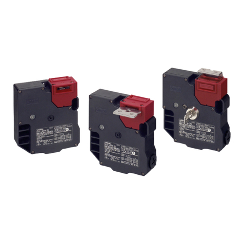
41,7±0,15
M4
22±0,1
4±0,1dia.1,5mmhighmax.
10±0,1
M4
22±0,1
41,7±0,15
38,7±0,1
Zwischenstück
Espaceur
Spaziatore
Espaciador
1 Fig.1 2 Fig.2
WICHTIGE SICHERHEITSHINWEISE
Definitionder Sicherheitsinformationen
VORSICHT
Weist auf eine mögliche Gefährdungssituation hin, die
bei Missachtung kleine, mittelschwere Verletzungen oder
Sachschäden hervorrufen kann.
Sicherheitsinformationen
GEFAHR
ÜberprüfenSiestetsdieFunktionderSicherheitsvorrichtungen,bevorSie dasSystem
in Betrieb nehmen. Wird diese Überprüfung nicht durchgeführt, besteht die Gefahr,
dass die Sicherheitsvorrichtungen nicht wie erwartet arbeiten, wenn die Verdrahtung
oder Einstellungen fehlerhaft sind oder die Schalter ausgefallen sind. Das gesteuerte
System setzt dadurch seinen Betrieb möglicherweise in einer Gefahrensituation fort,
waszuVerletzungenoderzumTodführenkann.
VORSICHT
"Stecken Sie den Betätiger nicht bei geöffneter Tür in den Schalter. Dadurch kann die
Maschineunerwartetanlaufen."
Wenden Sie keine Kraft an, die die spezifizierte maximale Zuhaltekraft übersteigt.
AndernfallsbestehtdieGefahreinerBeschädigungdesVerriegelungsmechanismusund
das SystemsetztseinenBetriebmöglicherweiseineiner Gefahrensituation fort, waszu
Verletzungen oder zum Tod führen kann Installieren Sie entweder eine weitere
Verriegelungseinrichtung (z. B. einen Riegel) zusätzlich zum Schalter oder verwenden
SieeineWarnmethodeoderAnzeige,durchdieabgezeigtwird,dassdasSystemgesperrt
ist, damit keine Kräfte angewendet werden, die die Zuhaltekraft im verriegelten
Zustandübersteigen.
Sicherheitsmaßnahmen
1. Vorsichtsmaßnahmenfürden sicheren Gebrauch
2. Es bestehtVerletzungsgefahr.DasProdukt beimAnbringennichtfallenlassen.
3. Lassen SiedasProdukt aufkeinenFallfallen, sonstkannes zu Funktionsstörungen desSchalterskommen.
4. Demontieren SiedasProduktauf keinen Fall oderbauenSie esum. Hierdurch kanneszuFunktionsstörungenkommen.
5. Verwenden Sie den Schalter nicht an Orten, wo explosive, entzündliche oder andere schädliche Gase vorhanden sein
können.
6. Installieren Sie den Betätiger so, dass er das Bedienungspersonal nicht berühren kann, während die Tür geöffnet oder
geschlossenwird.Dadurchkönnen Verletzungenhervorgerufen werden.
7. "Verwenden Sie das Produkt nicht in Wasser, in Öl oder an Orten, woes mit Wasser oder Öl inBerührung kommen kann.
WasseroderÖl könnenindas Produkteindringen.
(Der Schalter entspricht der Schutzart IP67, was bedeutet, dass er für einen bestimmten Zeitraumwasserdicht geblieben
ist, nachdemer ins Wassergelegt wurde.)"
8.Im Fall der Nutzung von MetallverbindungsstückendarfdieGewindelänge9mmnichtüberschreiten.
9. Wird ein 1/2-14 NPT-Stecker verwendet, kann es bei Beschädigung des Adapters zu einer Verschlechterung der
SchließeigenschaftenundzuStromschlagkommen.BitteverwendenSiekeineMetallsteckeroder–rohrverbindungen.
10. "Obwohl das Schaltergehäusegegen das Eindringenvon Stauboder Wasser geschützt ist,vermeidenSie dass Fremdkörper
durch dieBetätigerlöffnung eindringen.
AndernfallskannesinnerhalbkurzerZeitzu starkemVerschleißoderAusfall kommen."
11. SchaltenSiedieStromversorgung nichtein,währendSie dieVerdrahtungvornehmen.
12."AchtenSie unbedingt darauf,nachderVerdrahtungdieAbdeckungwiederzuschließen.
Schalten Sie die Stromversorgung nicht ein, wenn Sie die Abdeckung öffnen. Es besteht die
Gefahr eineselektrischen Schlages."
13. Um den Schalter vor Kurzschluss zu schützen, muss eine Sicherung vorgeschaltet werden. Die
Sicherungmussaufdas1,5bis2-fachedesNennstroms dimensioniertwerden.
Verwenden Siebitte eine 4AflinkeSicherunggemäßIEC60127, wenn Sie einenEN-Schalter verwenden.
14.SchaltenSiebei normaler Belastung (125VAC/1A) nicht gleichzeitigmehr als drei Stromkreiseein und aus.
Es kann sein,dasssichdieIsolations-Funktion verschlechtert.
15.DieLebensdauerdesSchalterswird in erheblichemMaßevondenBetriebsbedingungen beeinflusst.
PrüfenSiedaherdenSchalteruntertatsächlichenBetriebsbedingungenundhaltenSiedievorgeschriebene
HäufigkeitderSchaltzyklen ein.
16.Wartungbzw.Instandsetzung des Schaltersdürfennicht vomAnwendervorgenommenwerden.
Wenden Sie sichindiesemFallanden Hersteller.
17.BitteachtenSiedarauf,dassamKlemmenblockundan derLeiterplattekeine Fremdkörperhaftenbleiben.
Es kann sein,dassbeiKlemm-KurzschlussdieSicherheitbeeinträchtigtist.
REGLES DE SECURITE
Signification des avertissements
PRECAUTION
Une utilisation incorrecte de ce produit pourrait
donner lieuà des blessures de moindre ou moyenne
gravité et à des dégâts matériels.
Avertissements
DANGER
Vérifiez toujours le fonctionnement des dispositifs de sécurité avant le démarrage du
système. Le non-respect de cette règle peut entraîner le fonctionnement incorrect des
dispositifs de sécurité si le câblage ou les paramètres sont incorrects ou en cas de
défaillance des commutateurs. Il se peut que le système commandé continue à
fonctionner,provoquantdesblessuresoulamort.
PRECAUTION
Ceproduitpeuts’actionneretprovoquerdesdégâts.Nepasinsérerlacléd’actionnement
quandlaporteestouverte.
N'appliquez pas une force supérieure à la force de maintien maximale spécifiée. Le
non-
respect de cette règle peut endommager le mécanisme de verrouillage du
commutateur et il se peut que le système continue à fonctionner, provoquant des
blessuresoulamort.Installezplutôtunautresystèmedeverrouillage(parexempleun
dispositif d'arrêt) en plus du commutateur, ou utilisez une méthode ou un panneau
d'avertissementpourindiquerquelesystèmecommandéestverrouilléafind'éviterune
forcedemaintientropimportanteenmodedeverrouillage.
Precaution d'usage pour la sécurité
1. Il sepeutquele commutateur nefonctionnepaspleinement.Nefaitespastomberleproduit.
2. Risquedeblessure.Lorsdel'installationdel'appareil,veillez àcequ’il ne tombepas.
3. Nedémonter outrafiquerce produit enaucuncas.Celapourraitempêchersonfonctionnementnormal.
4. Nepas utiliserceproduitdansun environnement à gazexplosif,gazinflammableetc.
5. Installer la clé d’actionnement de sorte qu’elle ne vienne pas au contact de l’opérateur à l’ouverture/fermeture de la porte.
Desblessures sont possibles.
6. Nepas utiliser leproduitdansde l’huileou del’eau,ou dansunemplacement oùilpourrait àtoutmomentêtresoumisàdes
éclaboussuresd’huileoud’eau.Del’eauoudel’huilepourraitpénétreràl’intérieur.
(Le dispositif de protection IP67 contrôle la pénétration d’eau si ce commutateur est laissé dans l’eau pendant un certain
temps.)
7. Le commutateur lui-même est protégé contre la pénétration de la poussière ou de l’eau, mais éviter la pénétration de
matières étrangèresdansletroud’insertiondelaclé d’actionnementdelatête.Celapourraitprovoquer uneusure précoceou
desdégâts.
8. Lorsqu’un connecteur métallique est utilisé, ce dernier doit avoir une partie filetée d’une longueur inférieure ou égale à
9mm.
9. Lorsdel'utilisationduconnecteur ½-14NPT, il ya un risque de mauvaise isolationqui peut survenir à lasuite de la rupture
de l'adaptateur,ainsi queduchocélectrique. Nepasutiliserdeconnecteursni decâblesmétalliques.
10.Nepasmettresoustension lors ducâblage.Uneélectrocutionseraitpossible.
11. Ne pas oublier d’installer le couvercle après le câblage. Ne pas mettre sous tension quand le couvercle est ouvert. Une
électrocutionserait possible.
12.Connecter lecommutateur ensérieàun fusible à courantderupture de1,5à2foissupérieur
au courantnominal pouréviterles dommages dus àuncourt-circuitducircuit.
En casd'utilisation avec unecatégorieEN,veuillezutiliserdesfusiblesàfusion
ultra-rapideconformément austandardIEC60127.
13.Pourl'ouverture etlafermeture dechargeordinaire (125VAC,1A),nepasactionner 3 circuitsou
plus enmême temps,ou lacapacitéd'isolationrisqueraitde s'entrouver réduite.
14.Ladurabilité ducommutateurestfortement influencéeparlesconditionsde fonctionnement.
Vérifierlecommutateur dans les conditionsde fonctionnementréelles etl’utiliserdansdesl
imitesne posant pas deproblèmes.
15.L’utilisateurdoit faireappel à unagentdeservicedu fabricant pour laréparationetl’entretien,
et nepasleseffectuerlui-même.
16.Nepasutiliser cecommutateur commeretenue.Nepasinstallerderetenue,commeindiquésur
l’illustration,pourquelapartiecollier dela cléd’actionnement ne heurte paslatête.
17.Veuillezvousassurer qu'aucun élément collant negènelebornierdeconnexion ainsiquele circuit imprimé.
Lesterminauxpeuventcourt-circuiterentreeux etengendrer desproblèmessurlefonctionnementnormaldusystème
de sécurité.
PRECAUZIONI PER LA SICUREZZA
Significatodelle indicazioni di avvertenza
ATTENZIONE
Una operazione non corretta può anche causare, data
la sua potenziale pericolosità, ferite leggere o di medio
grado, oppure danni al materiale.
Indicazionediavvertenza
PERICOLO
Verificare sempre il funzionamento delle funzioni di sicurezza prima di avviare il
sistema. In caso contrario, le funzioni di sicurezza potrebbero non funzionare come
previstoseilcablaggiooleimpostazioninonsonocorretteoinpresenzadiunguastodel
finecorsa. Il sistema controllato potrebbe quindi continuare a funzionare ponendo in
gravepericolol'incolumitàdell'operatore(rischiodilesioniomorte).
ATTENZIONE
Non inserire la chiave di azionamento quando la porta di protezione è
aperta. L' apparecchio può iniziare a funzionare, causando danni fisici.
Nonapplicareuna forza superiore alla forza di ritenzione massimaspecificata. In caso
contrario, il meccanismo di blocco del finecorsa potrebbe danneggiarsi e il sistema
potrebbe continuare a funzionare ponendo in grave pericolo l'incolumità dell'operatore
(rischiodilesioniomorte).Installareundispositivodibloccoaggiuntivooltrealfinecorsa,
adesempiounfermo,oppureutilizzareunaspiaounmessaggiodiavvisopersegnalare
ilbloccodelsistemacontrollato,alfinedievitareilsuperamentodellaforzadi ritenzione
inmodalitàdiblocco.
Precauzioni per l'utilizzo in condizioni di sicurezza
1. Non farcadere il prodotto. Il finecorsapotrebbero funzionare nondebitamente.
2. C'è ilrischiodisubire danni fisici.Prestare ladovutaattenzionepernonfar cadere ilprodottonelmomentodelfissaggio.
3. Non effettuare alcuno smontaggio o modifica del prodotto per nessuna ragione. Potrebbe pregiudicare il suo regolare
funzionamento.
4. Nonadoperareilprodottoinambientiincuivisiagasesplosivooinfiammabile.
5. Collocare la chiave di azionamento in una zona in cui la chiave stessa non possa toccare il corpo dell’operatore nel momento
dell’apertura e dellachiusuradellaporta diprotezione. Essapotrebbeanchecausare ferite alle persone.
6. Nonadoporare il prodotto inacqua odinolioe neppureinambienti chepossono essere sempre bagnatidall’acqua odall’olio.
L’acqua e l’olio possono penetrare all’interno del prodotto. (La struttura protettiva IP67 del finecorsa accerta l’infiltrazione di
acqua in casochela permanenza nell’acqua siprotraeperun determinato tempo).
7. Il finecorsa stesso èprotetto dapenetrazionedipolvere odi acqua, pur tuttaviabisogna prestaremolta attenzionea chenon
si infiltrino corpi estranei dentro il foro per l’inserimento della chiave di azionamento della zona della testata.Le infiltrazioni
possonoessereunadellecausedelsuo deterioramento prematuro o dellasuarottura.
8. Qualora siadoperaunconnettoremetallico,utilizzarneunolacui vitenonsuperilalunghezzadi9mm.
9. L’uso di un connettore 1/2-14NPT può causare danni all’adattatore di conversione rendendo le guarnizioni difettose e
generandoil rischio discaricheelettriche.Nonutilizzarené connettorimetallici, nétubimetallici.
10.Nondarealimentazionedurante ilcollegamentodeifili.Ci potrebbe essereilrischio di scosse elettriche.
11. Dopo aver terminato il lavoro di collegamento dei fili montare sempre lacopertura prima di procedere al suo utilizzo. Non
attaccarela tensione conlacopertura aperta.Cipotrebbeessere ilrischiodiscosseelettriche.
12.Perevitare cheilfinecorsasirompaacausadicortocircuito,inserire,inseriealfinecorsa,
un fusibileconilvalore diinterruzionedi1,5a2volte piùdelvalorenominale.
Quandosiutilizza uninterruttoreditipoEN,utilizzareunfubileditipo4A(interruzionerapida),
compatibile conIEC60127.
13.All'apertura/chiusura di carichigenerali(125VAC, 1A), nonutilizzarepiù di 3circuitiallavolta.
La proprietà isolante potrebbe essere compromessa.
14.Laresistenzadelfinecorsa variaconilvariare dellecondizioni dell’apertura/chiusura. Perprocedere
al suoregolare utilizzo,provareilprodottosempre sottole condizionidiusorealeeadoperarloentro
un numerodiapertura/chiusurachenoncreiproblemidifunzionalità.
15.Perquantoriguardalamanutenzioneelariparazione,ilprodottodeve esseremanutenutooriparato
nondirettamentedall’utente ma, contattando il produttore dell’apparecchio(macchina).
16.Nonadoperare ilcorpoprincipalecomefermo.Installareassolutamenteunfermo,comeviene illustrato
neldisegno,perevitarechelatesadellachiavedi azionamento urticontrolazonadellatestata.
17.Evitare che corpiestranei penetrino nelbloccoterminaleonella base.
In caso di cortocircuito,c'èlapossibilità cheildispositivodisicurezzanonentri infunzionecorrettamente.
OBSERVACIONES PARALASEGURIDAD
Significadodelas indicacionesdeadvertencia
CUIDADO
Este producto, si no es empleado correctamente de
acuerdo con las instrucciones dadas, puede causar
lesiones levas o medianas o daños físicos.
Indicación deadvertencia
PELIGRO
Antes de iniciar el sistema, compruebe siempre el funcionamiento de las
característicasdeseguridad.Denohacerloasí,dichascaracterísticasdeseguridad
podrían no funcionar correctamente si el cableado o las configuraciones no son
correctos,osilosinterruptoreshanfallado.El sistemaqueestásiendocontrolado
puedeseguirfuncionandoyproducirlesionesolamuerte.
CUIDADO
El equipo puede funcionar, causando daños físicos. No inserte la llave de
operaciónenelestadoenquelapuertaestéabierta.
No aplicar fuerza que exceda a la fuerza máxima de sujeción especificada. De
hacerloasísepodríadañarel mecanismo debloqueodelinterruptoryelsistema
podría seguir funcionando y producir lesiones o la muerte. Instale otro
componente de bloqueo (porejemplo, un tope) además del interruptor, o useun
indicador o método de advertencia que muestre que el sistemacontrolado está
bloqueadoparaevitarlasobrecargadelafuerzadesujeción.
Precauciones para uso seguro
1. Lasfuncionesdelinterruptornopuedendesplegarse. No deje caer elproducto.
2. Existepeligro de sufrir lesiones.Alinstalarelproducto, tengamucho cuidado de nodejarlocaer.
3. En ningún caso,nodesmontenimodifiqueesteproducto,ya queestas acciones pueden impedircorrectofuncionamiento
delproducto.
4. Noutilice este producto enun medioambienteen queseencuentrengasesexplosivos oinflamables.
5. Coloque la llave de operación en un lugar enque ésta no se toque a su cuerpo al abrir la puerta. Si no, esto puede causar
daño.
6. No utilice este producto dentro del aceite o agua o en un medio ambiente en que constantemente salpica agua o aceite.
Hayprobabilidad deque el agua oaceitepenetre en el interior del producto.
(La estructura de protección IP67 de este interruptor es para confirmar la penetración del agua después de dejarlo en el
aguapor unlapso detiempodeterminado.)
7. El propio interruptor está protegido contra la penetración de polvos o agua, pero tenga cuidado de que no entre materia
extraña a través de la apertura para insertar la llave de operación que se encuentra en la parte de la cabeza. Esto puede
sercausa dedesgasteprematuroorompimiento.
8. Cuando utilice conectorde metal,queseauntornillomáscorto que9 mm.
9. En caso de usar el conector 1/2-14NPT, hay posibilidad de sellado defectuoso o sacudida eléctrica por la ruptura del
adaptadorde conversión.
10.Noaplique laelectricidadmientrasseefectúantrabajosdeconexiones. Hay probabilidaddeelectrosacudida.
11. Después del trabajo de conexiones, instale sin falta lacubierta. También no aplique la electricidad en el estado en que la
cubierta estáabierta. Hayprobabilidaddeelectrosacudida.
12.Conelfin deevitardeteriorodelinterruptor porelcortocircuitodelcircuito, conecteunfusiblecon
unacapacidad deruptura1,5a2veces lacorriente derégimen,enserie conelinterruptor.
Cuandose utilice elinterruptor en sistema EN, use un plomode4Aadaptable aIEC 60127.
13. No operemás de 3circuitos al mism tiempo en el pesogeneral(125VAC/1A).
Haypeligrodequeel límitedeinsulaciónse vea afectado.
14.Ladurabilidaddelinterruptor dependegrandementedelascondicionesde aperturay cierre.
Antesdeusarelinterruptor,confirmelaseguridaddelinterruptor instalado enla máquina
realparaverificarel número deveces tantode laaperturacomoelcierre.
15.Elmantenimientoyla reparación, nodeberánefectuarseporelpropiousuariodelas
instalaciones, sinopóngaseencontacto(consulta)conelfabricante delasinstalaciones(máquinas).
16.Noutiliceesteproductocomo unretén. Instalesinfaltaunreténtalcomosemuestraenlafigura
de modo queelbordedelallave deoperación nosecontacteconla cabeza.
17.Tengacuidadodeque noquedenobjetosextrañosen labaseyenelbloqueterminal.
En caso decortocircuito, hayposibilidadesde queeldispositivode seguridadno funcionecorrectamente.
EmpfohleneKlemmverbindungen
Terminauxdesertissagerecommandés
Terminaliconsistemadi crimpaturaraccomandati
Terminalesrizadasrecomendadas.
PHOENIX
CONTACT
AI0.34-8TQ(AWG22)
AI0.5-8WH(AWG20)
AI0.75-8GY(AWG18)
13579
246810
Verbindungsleitungs-Verarbeitungslänge
Longueurde procéduredufil deplomb
Lunghezza del cavo processante.
Longituddel cableprincipal.
L1
MAX
14mm
L2 MAX 8mm
30±3mm
40±3mm
1
3
5
7
9
2
4
6
8
10
Technische Daten
Elektrische Daten :AC-15 1,5A/120VAC / DC-13 0,22A/125VDC
NEMA C150,R150
Zwangsöffnungskraft :min.60N
Zwangsöffnungsweg :min.15mm
GeeigneteBetriebsgeschwindigkeit :0,05bis 1m/s
Max.Betriebsfrequenz :5 Zyklen/Min.
Kurzschlussschutz : Verwenden Sieeineflinke 4A-SicherunggemäßIEC60127.
Nennstoßspannung(Uimp) :1,5kV(ZwischenAnschlüssen unterschiedlicherPolarität)
Schutzartklasse : IP67(EN60947-5-1),TYPE4XINDOOR USE ONLY(UL,CSA)
Umgebungstemperatur : –10 bis 55 (ohne Vereisung)
Nennspannung :Magnetspule 24VDC
Warnleuchte 24VDC
Verdrahtung :AWG24bis 22 (0,2bis0,3mm
2
)
Caracteristiques Techniques
Caractéristiquesélectriques :AC-15 1,5A/120VAC / DC-13 0,22A/125VDC
NEMA C150,R150
Forced'ouverture positive :60Nmin.
Coursed'ouverturepositive :15mmmin.
Vitessedefonctionnementcorrecte : 0,05 à, 1m/s
Fréquencedefonctionnement :5opérations/ min
Dispositifdeprotectioncontre :Commedispositif anti-court-circuit, utiliserdes fusiblesà fusion
lescourts-circuits ultra-rapide4A(IEC60127).
Rigidité diélectrique(Uimp) : 1,5kV(Entre bornesdepolarités différentes)
Indice deprotection : IP67(EN60947-5-1) ,TYPE4XINDOORUSE ONLY(UL,CSA)
Température ambiante : en fonctionnementde-10 à 55 ,sansgivre
Tensionnominale :Solénoïde 24VDC
Voyant 24VDC
Câblage :AWG24à22(0,2à 0,3mm2)
Caratteristiche Tecniche
Datielettricinominali :AC-15 1,5A/120VAC / DC-13 0,22A/125VDC
NEMA C150,R150
Forzad’aperturapositiva : 60N min.
Corsa d’aperturapositiva : 15mm min.
Velocità di funzionamentoadeguata : 0,05a 1m/s
Massima frequenzaoperativa : 5cicli /min
Dispositivo di protezione contro :Utilizzare unfusibile 4Aadinterruzione rapida,
icortocircuiti compatibileconIEC60127.
Rigiditàdielettrica(Uimp) :1,5kV(Traterminalidipolarit àdifferente )
Gradodi protezione : IP67 (EN60947-5-1) ,TYPE4XINDOORUSE ONLY(UL,CSA)
Temperturaambientedi :–10 a55 (in assenzadiformazionedighiaccio)
funzionamento
Tensione nominale : Solenoide 24VDC
Lampadinadiindicazione 24VDC
Cablaggio :Da24a22AWG(da 0,2a 0,3mm2)
Características Técnicas
Valoreseléctricos :AC-15 1,5A/120VAC/ DC-13 0,22A/125VDC
NEMA C150,R150
Fuerza de aperturapositiva :60Nmín.
Carreradeapertura positiva :15mmmín.
Velocidaddeoperaciónadecuada : 0,05 a1 m/s
Frecuenciadeoperaciónmáxima : 5ciclos/ min
Dispositivo de proteccíon contra :Utilice unplomo rápidode4Acon IEC60127.
cortocircuito
Impulsodetensiónnodisruptive : 1,5kV(Entre losterminalesdepolaridaddistinta)
(Uimp)
Gradode protección :IP67 (EN60947-5-1)TYPE4XINDOOR USEONLY (UL, CSA)
Temperatura ambiente de : –10 a 55 (sinhielo)
funcionamiento
Tensiónderegimen :Solenoide 24VDC
Lámparaindicadora 24VDC
Cableado :AWG 24a 22(0,2a0,3 mm
2
)
Anzugsdrehmoment
Coupledeserrageapproprié
Coppiadiserraggioadeguata
Pardeaprieteapropiado
Klemmschraube
Vis deborne
Viteterminale
Tornillodelterminal
0,5 0,6N m
Befestigungsschraube für dieAbdeckung
Vis de montageducapot
Vitedibloccaggio delcoperchio
Tornillode montajedela cubierta
0,4 0,5N m
Befestigungsschraubefür die Betätiger
Vis de montagedelaclé
Vitedibloccaggio dellachiaveoperativa
Tornillo demontaje delpasador de operación
0,75 1,15N m
(D4SL-NK G)
2,4 2,8 N m
(D4SL-NK ,D4SL-NK S)
Befestigungsschraube für dasGehäuse(GrößeM4)
Vis de montageducorps
Vitedibloccaggio delcorpo(dimensioneM4)
Tornillode montajedelfinaldecarrera
0,75 1,15N m
Leitungseinführungfür Verschraubung
Ouverturedu conduit
Vitediapertura delconnettore del condotto
Conectorenel tornillo deapertura delconducto
1,8 2,2N m
(G1/2,M20)
1,4 1,8N
(1/2-14NPT)
BefestigungderTür
DiegeschlosseneTürmussmit einemRiegel
o.ä.gesichert werden,
so dass derBetätigerinnerhalb der
definiertenBetätigungszone bleibt.
Fixation de laporte
La porteferméedoitêtrebloquéeparun
crochet ou équivalentde
aniéreà ceque laclé setrouve àl'intérieur
delazone de réglage.
Posizionedella porta
Assicurarsiche,quandolaporta sitrova in
posizione chiusa, lachiave
operativa sia all'internodell'area di
regolazione.
Fijación de lapuerta
La puertacerradadebeasegurarse con un
cierreo similardetal forma
queelpasadordeoperaciónquededentrode
lazonadeajuste.
0,5-3mm
Abmessungen
Einheit: mm
Dimensions demontage Unité: mm
Dimensioni dimontaggio Unità: mm
Dimensionesdemontaje Unidad:mm
Betätiger
Clé
Chiaveoperativa
Pasadordeoperación
Größe derBohrungzumAnbringen desSchlosses
Tailledel’orificedefixationdel’appareil
Dimensione dellalavorazione del foroper il montaggio sulcorpo
Medidas para la elaboración del orificio para el montaje del equipo.
Sperrkopf Anschlag
Batätiger
Schalter
Tête Retenue
Clé
Commutateur
Testata Fermo
Chiave operativa
Finecorsa
Cabezal Retén
Pasador deoperación
Interruptor
Schaltbeispiel
Exempledeconnexiondes circuits
Esempio di collegamentodel circuito
Ejemplodeconexión del circuito
Türöffnungsprüfschalter
Interrupteur du détecteur d’ouverture/fermeture de porte
Interruttore di rilevamento dell'apertura e della chiusura dello sportello
Interruptor deinspección de apertura ycierre de la puerta.
Verriegelungsüberwachungsschalter
Interrupteur de contrôledeverrouillage
Interruttoredimonitoraggio del bloccaggio
Interruptor del monitor de bloqueo
zumRegelstromkreis
Vers lecircuit decontrôle
Perilcircuito dicontrollo
Haciael circuitodecontrol
zumSicherheitsstromkreis
Vers lecircuitdesécurité
Perilcircuitodisicurezza
Haciael circuitodeseguridad
zumRegelstromkreis
Vers lecircuit decontrôle
Perilcircuito dicontrollo
Haciael circuitodecontrol
zumSicherheitsstromkreis
Vers lecircuit desécurité
Perilcircuito disicurezza
Haciael circuitodeseguridad
E1
()
21
33
11
22
34
42
52
51
E2
()
12
41
64
63
7
3
1
10
8
4
2
9
5
6
for D4SL-N N -D
LED
E1
()
21
31
22
32
42
E2
()
41
62
61
7
3
1
10
8
4
2
9
5
6
for D4SL-N V
AND
Entriegelungsschlüssel
DasGewinde desEntriegelungsschlüssels nichtübermäßig belasten
(Anzugsmomentüber0,2Nm).
VorSchließenderAbdeckklappebitteden Entriegelungsschlüssel
inVerriegelungspositionbringen.
Clédelibération
Nepas appliquerune force excessive(0,2Nmouplus) surlapartie filetée
delaclédelibération.
Lorsquevousfermezlecouvercle,positionnezlaclé delibérationsur
lapositionLOCK.
In relazione alla chiave di liberazione
Nonesercitareunaforzaeccessiva(pari osuperiore a 0,2N m)
sulla vite dellachiavediliberazione.
Quandosichiude lacopertura,portarelachiavedi liberazionenella
posizione di bloccaggio.
Conrelacióna lallavedeliberación
Noapliqueexcesivafuerza(másde0,2N.m)
en la partedel tornillode la llavededesconexión.
Cuandocierre la cubierta, ponga en LOCK la llavededesconexión.
(forD4SL-N N -D
(forD4SL-N V -
Oberflächenbefestigung
Surfaced'installation
Superficiedifissaggio
Areade ensamblaje
Zwischenstück
Espaceur
Spaziatore
Espaciador
D4SL-N - D4SL-N - 4
LOCK
UNLOCK
LOCK
UNLOCK
2-M4
15±0,1
D4SL-NK1/-NK1S/-NK2
2-M4
12±0,1
or 20±0,1
D4SL-NK1G/-NK2G
40±0,1
D4SL-NK3
2-M4
M4
4±0.1 dia. 1.5mm high max
22±0.1
41.7±0.15
22±0.1
38.7±0.1
10±0.1
41.7±0.15
M4
4±0.1 dia. 1.5mm high max
41,7±0,15
M4
22±0,1
4±0,1dia.1,5mmhigh max.
10±0,1
M4
22±0,1
41,7±0,15
38,7±0,1
Zwischenstück
Espaceur
Spaziatore
Espaciador
(
(H2S SO2NH3HNO3Cl2)
H2S SO2NH3HNO3Cl2
6
1
LOCK UNLOCK
UNLOCK LOCK
D4SL-N A UNLOCK
D4SL-N G LOCK
UNLOCK
0.2N m
LOCK
0.5 0.6 N m
0.4 0.5 N m
D4SL-NK G 0.75 1.15 N m
D4SL-NK NK S 2.4 2.8 N m
0.75 1.15 N m
1.8 2.2 N m G1/2 M20
1.4 1.8 N m 1/2-14NPT
2
M4
4±0.1 1.5
1/2-14NPT
EMC EN1088 EN50047 GS-ET-19
EN60947-5-1 IEC60947-5-1, UL508 CSA C22.2 No.14
EN
AC-15 DC-13
AC120V DC125V
1.5A 0.22A
UL CSA
C150 R150
AC120V DC125V
1800VA 28VA
180VA 28VA
( ) 15mm
( ) 60N
1300N GS-ET-19
0.05 1m/s
5 /
100A
4A (IEC60127)
IP67(EN60947-5-1) ( IP00)
TYPE 4X INDOOR USE ONLY (UL, CSA)
DC5V 1mA ( )
10 55 ( )
95 RH
100
15 (AC125 1A )
DC24V+10 /-15
-
D4SL-N |N/P/Q/R| - 6.4W-0.27A
D4SL-N | | - 4.8W-0.2A
2.6W 0.15A
(LED) DC24V 10mA
B10d 2,000,000
ON/OFF
a)
b)
c)
d) 24
e)
*
0120-919-066
PHS
055-982-5015
8 00 21 00 365
FA
055-977-6389
9 00 12 00/13 00 17 30
FAX
FAX 055-982-5051
2-7. Be sure to install a cover after the wiring.
Do not put the electric power when opening a cover.
Do not put the electric power when wiring.
2-8. Makesurethatforeignsubstance doesnotadheretotheboard.. Ashort-circuitbetweenboard
terminalsmay occur,causingthesafetyfunctionsdisabled.
3. Mounting
3-1. Be careful not to drop your D4SL-N, or the switch will
not fully exhibit its ability.
3-2. This may cause a risk of personal injury.
Extra care must be taken not to drop this Product
during installation..
3-3. Install operation key so that it will not hit the operator
when the door is open. Injury may be caused.
3-4.Do not use the switch as a stopper.
Be sure to install a stopper as shown in the following
illustration to prevent the edge of the operation key
from inadvertently hitting the switch directly.
4. Others
4-1. Do not disassemble or remodel your D4SL-N in any case, or the D4SL-N will
not operate normally.
4-2. Evaluate the switch under actual working conditions before permanent
installation.
The durability of the switch is seriously affected by operating conditions.
4-3. Please mention in machine manufacturer’s Instruction.
Manual that the user must not repair nor maintain the switch and must
contact machine manufacturer for them.
Precautions for Correct Use
1. About the solenoid lock type
1-1. Be sure to energize the solenoid with the door closed (with the operation key
inserted). A malfunction will occur in Solenoid lock when energizing the
solenoid before closing the door.
1-2. In the solenoid lock type, a lock is closed only when the solenoids are energized.
A lock may be opened when the passage of an electric current to the solenoid is
stopped due to sudden power failure. Do not use the solenoid lock type for the
machine in which the inside of the door remains dangerous even after
shutdown of the machine.
2. Environment
2-1. The switch is intended for indoor use only.
2-2. Do not use your D4SL-N outdoor, or the switch will malfunction.
2-3. Do not use your D4SL-N in the atmosphere of hazardous gases (H2S, SO2, NH3,
HNO3, CI2, etc.) or high temperature and humidity, or it will cause the
imperfect closing of the contacts or the breakage thereof stemming from
corrosion.
2-4. Do not use the switch under any of the conditions mentioned below.
Frequent temperature range.
High humidity or dew condensation may be generated.
Where the switch is subject to severe vibration.
Where the metal dust, oil, or chemical is sprayed inside the door.
Where thinner is applied.
3. Storage
3-1. Do not keep the switch in dusty, humid place and any place where gas may be
present for example H2S, SO2, NH3, HNO3, Cl2..
3-2. A switch that has been stored for more than six months must be checked again
before use.
4. Using the release key (See Figure 1)
4-1. The release key is used to open a lock in the case of power failure or
emergency.
4-2. Turn the release key from the LOCK position to the UNLOCK position to
release the lock. This can open the safety door. (For the mechanical lock type
only.)
4.3. When the release key is turned to the UNLOCK position for maintenance or
other purposes, make sure to turn it back to the LOCK position before using it.
4-4. The set position of the release key at the shipping of the switch is as noted
below;
D4SL-N A : UNLOCK position D4SL-N G : LOCK position
4-5. While the release key is in the UNLOCK position, a lock is not closed and a
machine is not activated even when the door is closed in the course of
preliminary adjustment work performed inside a large machine or a
depressing type machine.
4-6. Do not use the release key when starting or stopping the machine.
4-7. The releasing of the auxiliary lock must be handled by an authorized person.
4-8. Do not apply an excessive force (of 0.2N m or more) to the threaded portion of
the release key. The release key may be damaged to the extent that it no
longer becomes operational.
4-9. To avoid an unauthorized person's access to the release mechanism, set the
release key to the LOCK position, and then seal the release key with a seal
wax (or wax coatings).
5. Installing the cover
5-1. Confirm that the seal rubber has no abnormality and then use it.
If the seal rubber is displaced or floated, or if foreign matters adhere to the seal
rubber, the seal rubber will lose its sealing capability.
5-2. Do not use any screw other than correct one, or the sealing capability of the
seal rubber will deteriorate.
6. About the hinge type door
6-1. A door is mounted near a hinge, excessive load may be imposed beyond a force
acting on the lock portion of this Equipment. This may result in damage to the
lock mechanism. Mount it to a position near a handle.
7. Mounting method
7-1. Mounting screw tightening torque loose mounting may result in malfunction.
Fasten the screws to the specified torque.
Terminal screw
0.5 to 0.6 N m
Cover clamping screw
0.4 to 0.5 N m
Operation key clamping screw (D4SL-NK G
0.75 to 1.15 N m
Operation key clamping screw
(D4SL-NK ,NK S)
2.4 to 2.8 N m
Body clamping screw
0.75 to 1.15N m
Conduit mounting connection
1.8 to 2.2 N m (G1/2,M20)
1.4 to 1.8 N m (1/2-14NPT)
Use below listed connector to secure IP67.
Size Manufacturer Type
Adequate cable
Diameter
G1/2
LAPP
ST-PF1/2 5380-1002
6.0 to 12.0 mm
ACE
SERVICE
LS-2G
(Short type)
6.0 to 11.0 mm
M20
LAPP
ST-M20
×
1.5
5311-1020
7.0 to 13.0 mm
1/2-14NPT
LAPP
ST-NPT1/2 5301-6030
6.0 to 12.0 mm
Use an optional seal packing (Type: JPK-16 or GPM20).
Tighten the seal packing to a proper tightening torque.
LAPP is a German manufacturer.
Ace Service is a Japanese manufacturer.
Before a connector of 1/2-14NPT size is used, install a supplied conversion
adapter on the switch and wrap it in seal tape.
11. Others
11-1. Please do a regular check in premeditation for this switch
12. Technical specification
Conformity : Machine Directive, Low Voltage Directive, EMC Directive,
EN1088 EN50047,GS-ET-19
Approval EN60947-5-1 IEC60947-5-1 UL508 CSA
C22.2 No.14
EN electrical rating
Utilization category AC-15/DC-13
Rated Voltage 120VAC / 125VDC
Rated Current 1.5A / 0.22A
UL, CSA electrical rating
C150 R150
Voltage 120VAC 125VDC
Volt Amp. Make 1800VA 28VA
Break 180VA 28VA
Overvoltage Category
Direct opening travel (min.) 15 mm
Direct opening force (min.) 60 N
Holding force (min.) 1300N (GS-ET-19)
Operating speed 0.05 to 1 m/s
Operating frequency 5 operation / minute max.
Conditional short-circuit current 100A
Short circuit protective device Use 4 A fast acting fuse in accordance with
IEC 60127
Enclosure rating IP67 (EN60947-5-1) (Operation key insertion face : IP00)
TYPE 4X INDOOR USE ONLY (UL, CSA)
Minimum permissible load:5VDC,1mA resistive load (N level : reference value)
Ambient temperature range -10 to +55
(Protect against Frost)
Ambient humidity (max.):95%RH
Mechanical durability (min.) 1,000,000 operations
Electrical durability (min.) 150,000 operations
(125VAC,1A resistive load)
Solenoid Rated working voltage 24VDC+10%/-15%
Power-Current consumption
Inrush
D4SL-N |N/P/Q/R | -Approximately 6.4W-0.27A
D4SL-N |A/B/C/D/E/F/G/H/S/T/U/V | -
Approximately 4.8W-0.2A
Constant Approximately 2.6W-0.15A (max.)
Indicator lamp(LED) Rated voltage 24VDC
Current consumption Approximately 10mA
B10d : 2,000,000
There is no equality between the ON/OFF motions of a contact.
The switch contacts are common use for general load and micro load but, after
switching a general load, it is impossible to switch a micro load with the same
contacts. The contact reliability would be decrease due to the rough contact
surface.
Liability for use in safety systems
OMRON shall not be responsible for conformity with any standards, codes, or
regulations that apply to the combination of the products in the customer's
application or use of the product.
Take all necessary steps to determine the suitability of the product for the systems,
machines, and equipment with which it will be used.
Know and observe all prohibitions of use applicable to this product.
NEVER USE THE PRODUCTS FOR AN APPLICATION INVOLVING SERIOUS
RISK TO LIFE OR PROPERTY WITHOUT ENSURING THAT THE SYSTEM AS
A WHOLE HAS BEEN DESIGNED TO ADDRESS THE RISKS, AND THAT THE
OMRON PRODUCT IS PROPERLY RATED AND INSTALLED FOR THE
INTENDED USE WITHIN THE OVERALL EQUIPMENT OR SYSTEM.
See also Product catalog for Warranty and Limitation of Liability.
OMRON Corporation Industrial Automation Company
OMRON EUROPE B.V.
Wegalaan 67-69-2132 JD Hoofddorp The Netherlands
Tel: (31)2356-81-300 / Fax: (31)2356-81-388
OMRON ASIA PACIFIC PTE. LTD.
No. 438A Alexandra Road # 05-05/08 (Lobby 2),Alexandra Technopark, Singapore
119967
Tel: (65) 6835-3011 / Fax: (65) 6835-2711
OMRON SCIENTIFIC TECHNOLOGIES INC.
6550 Dumbarton Circle, Fremont CA 94555-3605 U.S.A.
Tel: (1) 510-608-3400 / Fax: (1) 510-744-1442
OMRON (CHINA) CO., LTD.
Room 2211, Bank of China Tower, 200 Yin Cheng Zhong Road,PuDong New Area,
Shanghai, 200120, China
Tel: (86) 21-5037-2222 / Fax: (86) 21-5037-2200
Traceability Information
Representative in EU
OMRON EUROPE B.V.
Wegalann 67-69 2132 JD Hoofddorp
The Netherlands
Manufacturer
OMRON CORPORATION, Safety Device Division
Shiokoji Horikawa, Shimogyo-ku, Kyoto, 600-8530JAPAN
E1
()
21
33
11
22
34
42
52
51
E2
()
12
41
64
63
7
3
1
10
8
4
2
9
5
6
for D4SL-N N -D
LED
Lock Monitor Switch)
To Safety Circuit
To Control Circuit
To Safety Circuit
Door Open/Close
Detection Switch)
To Control Circuit
E1
()
21
31
22
32
42
E2
()
41
62
61
7
3
1
10
8
4
2
9
5
6
for D4SL-N V
Lock Monitor Switch)
To Control Circuit
To Safety Circuit
Door Open/Close
Detection Switch)
To Control Circuit
AND
D4SL-N -
D4SL-N - 4
LOCK
UNLOCK
LOCK
UNLOCK
D4SL-NK3
D4SL-NK1G/-NK2G
D4SL-NK1/-NK1S/-NK2
6 Fig.6
M4
Front
4±0.1 dia. 1.5mm high max
22±0.1
41.7±0.15
Side
22±0.1
38.7±0.1
10±0.1
41.7±0.15
M4
4±0.1 dia. 1.5mm high max
1 Fig.1
3 Fig.3
5 Fig.5
4 Fig.4
2 Fig.2
1
3
5
7
9
2
4
6
8
10
2-M4
15
±
0.1
2-M4
40
±
0.1
2-M4
12
±
0.1
or 20±0.1
Head
This manual suits for next models
1
Other Omron Switch manuals

Omron
Omron D4DL User manual

Omron
Omron D4DS User manual

Omron
Omron D4NH - User manual

Omron
Omron D5C Series User manual

Omron
Omron E2EZ-X D User manual

Omron
Omron SHL - User manual

Omron
Omron D4JL-1NFA-C5 User manual

Omron
Omron E3L-2RC4 User manual

Omron
Omron E3G-L77 User manual

Omron
Omron D4N Series User manual

Omron
Omron B3SN-3012 User manual

Omron
Omron A8L Installation instructions

Omron
Omron D40ML Series User manual

Omron
Omron D4E-N - User manual

Omron
Omron ER5018 User manual

Omron
Omron X User manual

Omron
Omron D40A-G9SX-NS - User manual

Omron
Omron 61F-G User manual

Omron
Omron H5S - User manual

Omron
Omron A3A Series User manual