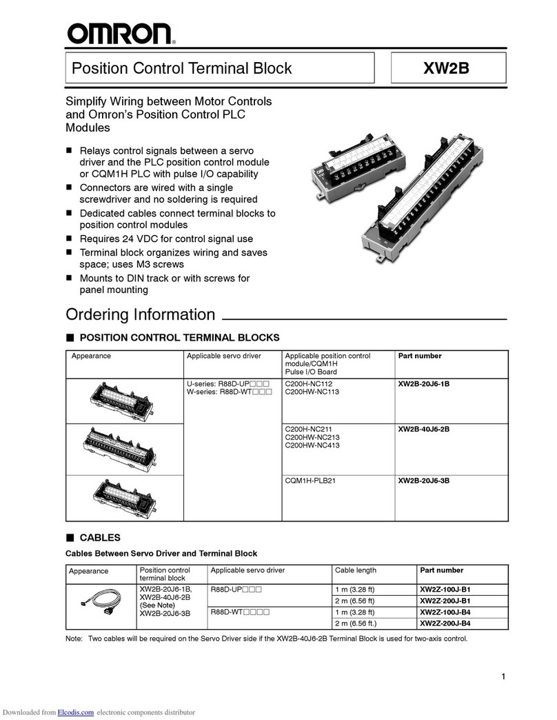
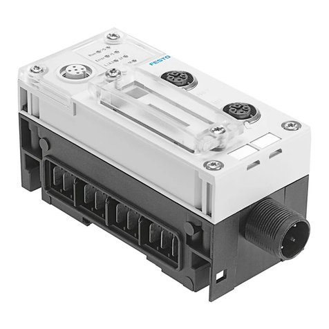
Omron SRT2-PD16T User manual

9
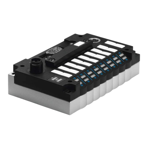
Transistor Remote Terminal Blocks SRT2-P
PP
PD16T
CompoBus/S Transistor I/O Terminal
Blocks Offer Individual Common
Terminals for Each Point
1SRT2 terminals support both high-
speed communications (750 kbps) and
long-distance communications (500 m)
systems, switch selected
1Removable circuit blocks simplify
long-term maintenance
13 tiers of terminals provide individual
common wiring points
1DIN track and screw mounting
Ordering Information
I/O points I/O classification Internal I/O circuit
common Rated voltage I/O rated voltage Part number
16 Input NPN (+ common) 24 VDC 24 VDC SRT2-ID16T
PNP (-- common) SRT2-ID16T-1
8 each Inputs and outputs NPN (+ common) SRT2-MD16T
PNP (-- common) SRT2-MD16T-1
16 Output NPN (-- common) SRT2-OD16T
PNP (+ common) SRT2-OD16T-1
3ACCESSORIES
Item Specification Part number
Communications cable Flat cable, 100 m length, 4 conductor (0.75 mm2each) SCA1-4F10
Branch connector Sold in packs of 10 SCN1-TH4
Extension connector Sold in packs of 10 SCN1-TH4E
Connector terminator Sold in packs of 10 SCN1-TH4T
Terminal block terminator Sold in packs of 10 SRS1-T

SRT2-P
PP
PD16T SRT2-P
PP
PD16T
2
Specifications
3RATINGS
Inputs
Input current 6 mA max./point at 24 V and 3 mA min./point at 17 V
ON delay time 1.5 ms max.
OFF delay time 1.5 ms max.
ON voltage 15 VDC min. between each input terminal and V terminals
15 VDC min. between each input terminal and G terminals
OFF voltage 5 VDC max. between each input terminal and V terminals
5 VDC max. between each input terminal and G terminals
OFF current 1mAmax.
Insulation method Photocoupler
Input indicators LED (green)
Outputs
Rated output current 0.5 A/point
Residual voltage 1.2 V max.
ON delay time 0.5 ms max.
OFF delay time 1.0 ms max.
Leakage current 0.1 mA max.
Insulation method Photocoupler
Output indicators LED (green)
3CHARACTERISTICS
Communications power supply
voltage 14 to 26.4 VDC
I/O power supply voltage 24 VDC +10%/--15%
I/O power supply current 4 A max./common
Current consumption (See Note) 50 mA max. at 24 VDC
Connection method Multi-drop method and T-branch method
Secondary branches cannot be connected to T-branch lines.
Dielectric strength 500 VAC for 1 min between insulated circuits
Noise immunity ±1.5 kV with a pulse width of 100 ns to 1 µs
Vibration resistance 10 to 150 Hz, 1.0 mm double amplitude or 70 m/s2
Shock resistance 200 m/s2
Mounting strength No damage when 100 N pull load was applied in all directions
Terminal strength No damage when 100 N pull load was applied
Screw tightening torque 0.3to0.5N:m
Ambient temperature Operating: --10°Cto55
°C(14
°F to 131°F) with no icing or condensation
Storage: --25°Cto65
°C(--13
°F to 149°F) with no icing or condensation
Ambient humidity Operating: 35% to 85% RH with no condensation
Weight 300 g max.
Note: The above current consumption is the value with all points turned ON excluding the current consumption of the external sensor
connected to the input Remote Terminal and the current consumption of the load connected to the output Remote Terminal.
SRT2-P
PP
PD16T SRT2-P
PP
PD16T
3
Nomenclature
ERR Indicator: Indicates communications errors.
COMM Indicator: ON while the Module is in data communication.
Power Indicator
Communications DIP Switch
The DIP switch is on the left-
hand side under the cover on
the upper part of the Remote
I/O Terminal.
Address Setting Switch
Set the rotary switch to the node
address by referring to the
following table.
I/O Indicators
M4 Mounting Screw
Terminal Cover
The Module stops operating with the
cover opened.
I/O and I/O Device Power Supply Terminals 8 to 15
These terminals will be used as output terminals 0
through 7 if the connected device handles both input
and output signals.
I/O and I/O Device Power Supply Terminals 0 to 7
These terminals will be used as input terminals if the
connected device handles both input and output
signals. I/O Power Supply Terminals
Connect 24 VDC I/O power supply
Fixture Track
Used for DIN track mounting.
CompoBus/S Internal Power Supply
Terminals (BS+ and BS--)
CompoBus/S Communications Cable
Terminals (BDH and BDL)
3INDICATORS
Indicator Display Color Meaning
PWR Lit Green The communications power supply is ON.
Not lit The communications power supply is OFF.
COMM Lit Yellow Normal communications
Not lit A communications error has occurred or the Module is in standby status.
ERR Lit Red A communications error has occurred.
Not lit Normal communications or the Module is in standby status.
0to15 Lit Yellow The corresponding I/O signal is ON.
Not lit The corresponding I/O signal is OFF.
3DIP SWITCH SETTINGS
Pins 1 and 2 are reserved. The
default setting is always OFF.
Baud Rate Setting
Mode Pin 3 Setting
Long distance ON Sets the I/O block to communicate in a long distance (500 m at 93.75 kbps) CompoBus/S system.
High speed OFF (default) Sets the I/O block to communicate in a high speed (750 kbps at 100 m) CompoBus/S system.
Output HOLD/CLEAR Mode
Mode Pin 4 Setting
HOLD ON Output status is maintained.
CLEAR OFF (default) Output status is cleared when a communications error occurs.

SRT2-P
PP
PD16T SRT2-P
PP
PD16T
4
Node Number Settings
Node address Setting (Hex) Node address Setting (Hex) Node address Setting (Hex)
006612 C
117713 D
228814 E
339915 F
4 4 10 A− −
5 5 11 B− −
Note: For node number settings, refer to the
CompoBus/S Operation Manual (W266).
Dimensions
Unit: mm (inch)
SRT2-ID16T (-1)
SRT2-MD16T (-1)
SRT2-OD16T (-1)
Mounting Holes
Two, 4.2 dia. or M4
180 (7.09)
170
50
(1.97)
40
3.15
57.5
(2.26)
170 ±0.2 (6.69 ±0.008)
40 ±0.2
(1.57
±0.008)

SRT2-P
PP
PD16T SRT2-P
PP
PD16T
5
Installation
3INTERNAL CIRCUIT CONFIGURATION
SRT2-ID16T SRT2-MD16T
SRT2-ID16T-1 SRT2-MD16T-1
SRT2-OD16T
SRT2-OD16T-1
DC-DC converter
(isolated type)
Photocoupler
Photocoupler
Inputs
(0 to 7)
Inputs
(8 to 15)
DC-DC converter
(isolated type)
Photocoupler
Photo-
coupler
Inputs
(0 to 7)
Inputs
(0 to 7)
DC-DC converter
(isolated type)
Photo-
coupler
Photo-
coupler
Inputs
(0 to 7)
Inputs
(8 to 15)
DC-DC converter
(isolated type)
Photocoupler
Photocoupler
Inputs
(0 to 7)
Inputs
(8 to 15)
DC-DC converter
(isolated type)
Photocoupler
Photocoupler
Inputs
(0 to 7)
Outputs
(0 to 7)
DC-DC converter
(isolated type)
Photocoupler
Photocoupler
Outputs
(0 to 7)
Outputs
(8 to 15)
I/O
power
supply
I/O
power
supply
I/O
power
supply
Internal circuit
Internal circuit
Internal circuit
Internal circuit
Internal circuit
Internal circuit
Voltage
drop Voltage
drop
Voltage
drop Voltage
drop
Voltage
drop
Voltage
drop
3EXTERNAL CONNECTIONS
Input (NPN Models)
S
RT2-ID16T, SRT2-MD16T Output (NPN Models)
SRT2-OD16T, SRT2-MD16T Input (PNP Models)
SRT2-ID16T-1, SRT2-MD16T-1 Output (PNP Models)
SRT2-OD16T-1, SRT2-MD16T-1
Two-wired sensor Three-wired sensor Three-wired sensor
Solenoid, valve, etc. Solenoid, valve, etc.
Blue (Black)
Brown (White)
Blue (Black)
Brown (Red)
Black (White)
Black (Black)
Blue (Red)
Brown (White)

SRT2-P
PP
PD16T SRT2-P
PP
PD16T
Precautions
Refer to the
CompoBus/S Operation Manual (W266)
before using the Unit.
Cat. No. GC RIO-1 04/00 Specifications subject to change without notice. Printed in U.S.A.
OMRON ELECTRONICS, INC.
OneEastCommerceDrive
Schaumburg, IL 60173
NOTE: DIMENSIONS SHOWN ARE IN MILLIMETERS. To convert millimeters to inches divide by 25.4.
1-800-55-OMRON
OMRON CANADA, INC.
885 Milner Avenue
Scarborough, Ontario M1B 5V
8
416-286-6465
9
Table of contents
Other Omron Terminal Block manuals
Popular Terminal Block manuals by other brands

Hubbell
Hubbell BASETRAK PB2 Series installation instructions

National Instruments
National Instruments VXI-TB-196 installation guide

National Instruments
National Instruments SCXI-1325 installation guide

National Instruments
National Instruments SCXI-1300 installation guide

Vallox
Vallox BlueSky air distribution box 6 outlets Installation

National Instruments
National Instruments SCXI-1303 installation guide